Page 761 of 2267
Wiring DiagramNCEC0434
YEC792
IGNITION SWITCH
ON or START
Refer to
EL-POWER.: Detectable line for DTC
: Non-detectable line for DTC
FUSE
BLOCK
(J/B)
ECM
Refer to last page (Foldout page) INJECTOR
No.1INJECTOR
No.2INJECTOR
No.3INJECTOR
No.4
INJECTORQG16I18DE
Wiring Diagram
EC-319
Page 763 of 2267

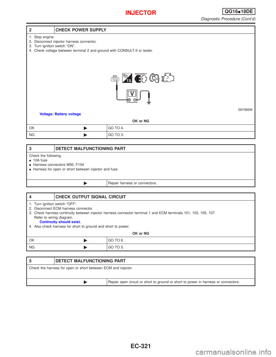
2 CHECK POWER SUPPLY
1. Stop engine.
2. Disconnect injector harness connector.
3. Turn ignition switch ªONº.
4. Check voltage between terminal 2 and ground with CONSULT-II or tester.
SEF986WVoltage: Battery voltage
OK or NG
OK©GO TO 4.
NG©GO TO 3.
3 DETECT MALFUNCTIONING PART
Check the following.
I10A fuse
IHarness connectors M50, F104
IHarness for open or short between injector and fuse
©Repair harness or connectors.
4 CHECK OUTPUT SIGNAL CIRCUIT
1. Turn ignition switch ªOFFº.
2. Disconnect ECM harness connector.
3. Check harness continuity between injector harness connector terminal 1 and ECM terminals 101, 103, 105, 107.
Refer to wiring diagram.
Continuity should exist.
4. Also check harness for short to ground and short to power.
OK or NG
OK©GO TO 6.
NG©GO TO 5.
5 DETECT MALFUNCTIONING PART
Check the harness for open or short between ECM and injector.
©Repair open circuit or short to ground or short to power in harness or connectors.
INJECTORQG16I18DE
Diagnostic Procedure (Cont'd)
EC-321
Page 766 of 2267
Wiring DiagramNCEC0545
YEC793
ENGINE
CONTROL
MODULE
RELAY
CONDENSER Refer to EL-POWER. BATTERY
: Detectable line for DTC
: Non-detectable line for DTC
Next pageNext page
IGNITION SIGNALQG16I18DE
Wiring Diagram
EC-324
Page 767 of 2267
YEC794
Preceding
page
IGNITION
COIL No. 4
(WITH POWER
TRANSISTOR) IGNITION
COIL No. 2
(WITH POWER
TRANSISTOR)
SPARK
PLUG
IGNITION
COIL No. 1
(WITH POWER
TRANSISTOR)IGNITION
COIL No. 3
(WITH POWER
TRANSISTOR)SPARK
PLUG
SPARK
PLUGSPARK
PLUG
Preceding
page
: Detectable line for DTC
: Non-detectable line for DTC
IGNITION SIGNALQG16I18DE
Wiring Diagram (Cont'd)
EC-325
Page 770 of 2267
6 CHECK IGNITION COIL POWER SUPPLY CIRCUIT-III
1. Turn ignition switch OFF.
2. Disconnect ECM relay.
SEF984W3. Check harness continuity between ECM relay terminal 7 and condenser terminal 1. Refer to wiring diagram.
Continuity should exist.
4. Also check harness for short to ground and short to power.
OK or NG
OK©GO TO 8.
NG©GO TO 7.
7 DETECT MALFUNCTIONING PART
Check the following.
IHarness connectors F73, E90
IHarness for open or short between ECM relay and condenser
©Repair open circuit or short to ground or short to power in harness or connectors.
8 CHECK IGNITION COIL POWER SUPPLY CIRCUIT-IV
1. Check voltage between ECM relay terminal 6 and ground with CONSULT-II or tester.
SEF368X
OK or NG
OK©GO TO 10.
NG©GO TO 9.
9 DETECT MALFUNCTIONING PART
Check the following.
I15A fuses
IHarness for open and short between ECM relay and fuse
©Repair or replace harness or connectors.
IGNITION SIGNALQG16I18DE
Diagnostic Procedure (Cont'd)
EC-328
Page 771 of 2267
10 CHECK ECM RELAY
1. Apply 12V direct current between ECM relay terminals 1 and 2.
2. Check continuity between ECM relay terminals 3 and 5, 6 and 7.
SEF296X
OK or NG
OK©GO TO 18.
NG©Replace ECM relay.
11 CHECK CONDENSER GROUND CIRCUIT FOR OPEN AND SHORT
1. Turn ignition switch OFF.
2. Check harness continuity between condenser terminal 2 and engine ground. Refer to wiring diagram.
Continuity should exist.
3. Also check harness for short to ground and short to power.
OK or NG
OK©GO TO 12.
NG©Repair open circuit or short to ground or short to power in harness or connectors.
12 CHECK CONDENSER
Refer to ªComponent Inspectionº, EC-QG-331.
SEF369X
OK or NG
OK©GO TO 13.
NG©Replace condenser.
IGNITION SIGNALQG16I18DE
Diagnostic Procedure (Cont'd)
EC-329
Page 772 of 2267

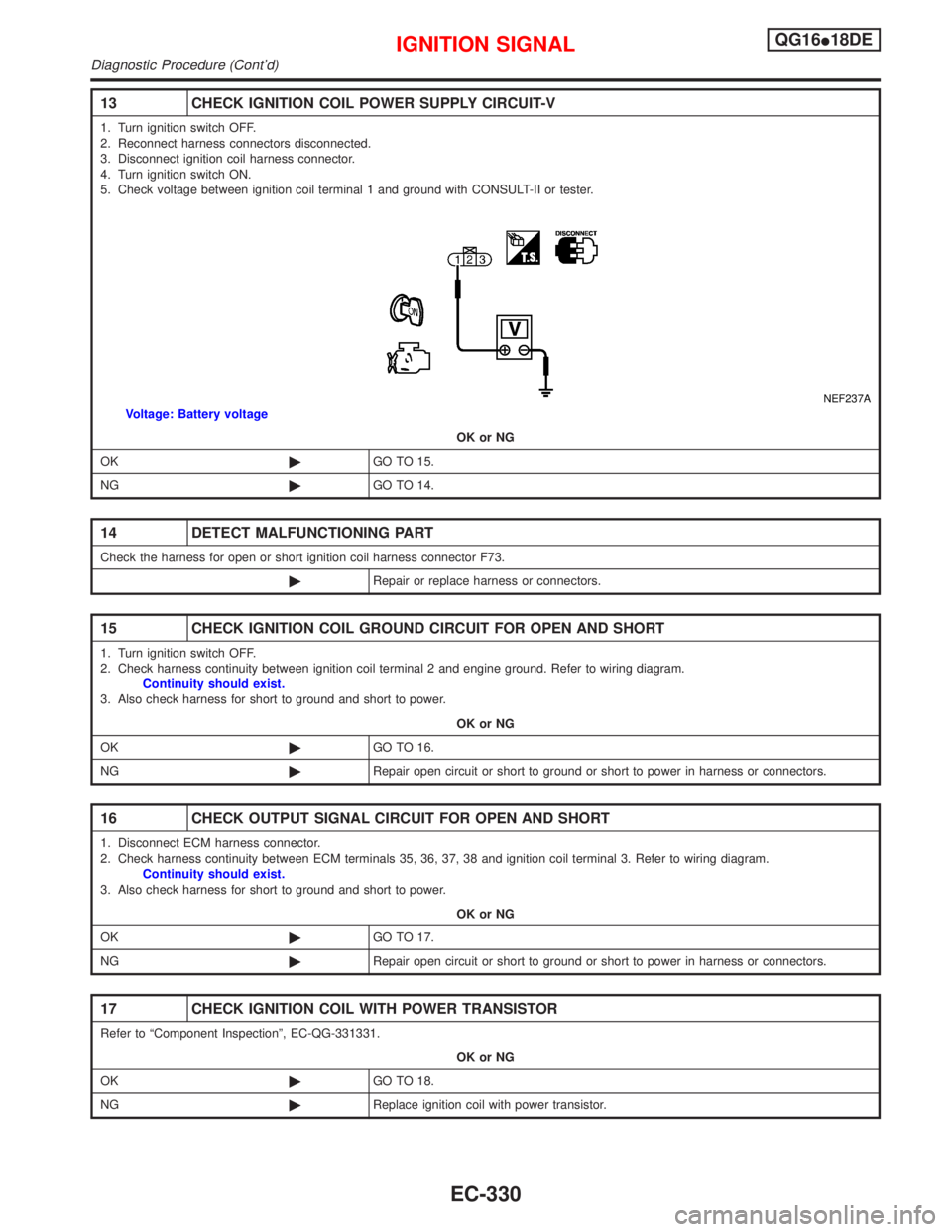
13 CHECK IGNITION COIL POWER SUPPLY CIRCUIT-V
1. Turn ignition switch OFF.
2. Reconnect harness connectors disconnected.
3. Disconnect ignition coil harness connector.
4. Turn ignition switch ON.
5. Check voltage between ignition coil terminal 1 and ground with CONSULT-II or tester.
NEF237AVoltage: Battery voltage
OK or NG
OK©GO TO 15.
NG©GO TO 14.
14 DETECT MALFUNCTIONING PART
Check the harness for open or short ignition coil harness connector F73.
©Repair or replace harness or connectors.
15 CHECK IGNITION COIL GROUND CIRCUIT FOR OPEN AND SHORT
1. Turn ignition switch OFF.
2. Check harness continuity between ignition coil terminal 2 and engine ground. Refer to wiring diagram.
Continuity should exist.
3. Also check harness for short to ground and short to power.
OK or NG
OK©GO TO 16.
NG©Repair open circuit or short to ground or short to power in harness or connectors.
16 CHECK OUTPUT SIGNAL CIRCUIT FOR OPEN AND SHORT
1. Disconnect ECM harness connector.
2. Check harness continuity between ECM terminals 35, 36, 37, 38 and ignition coil terminal 3. Refer to wiring diagram.
Continuity should exist.
3. Also check harness for short to ground and short to power.
OK or NG
OK©GO TO 17.
NG©Repair open circuit or short to ground or short to power in harness or connectors.
17 CHECK IGNITION COIL WITH POWER TRANSISTOR
Refer to ªComponent Inspectionº, EC-QG-331331.
OK or NG
OK©GO TO 18.
NG©Replace ignition coil with power transistor.
IGNITION SIGNALQG16I18DE
Diagnostic Procedure (Cont'd)
EC-330
Page 775 of 2267
Wiring DiagramNCEC0440
YEC282
BATTERY
Refer to EL-POWER.
: Detectable line for DTC
: Non-detectable line for DTC
FUSE
BLOCK
(J/B) IGNITION
SWITCH
REFER TO THE FOLLOWING
FUSE BLOCK - Junction Box (J/B)
FUSE BLOCK - Junction Box (J/B) OFF
ACC
ONST
START SIGNALQG16I18DE
Wiring Diagram
EC-333