Page 737 of 2267
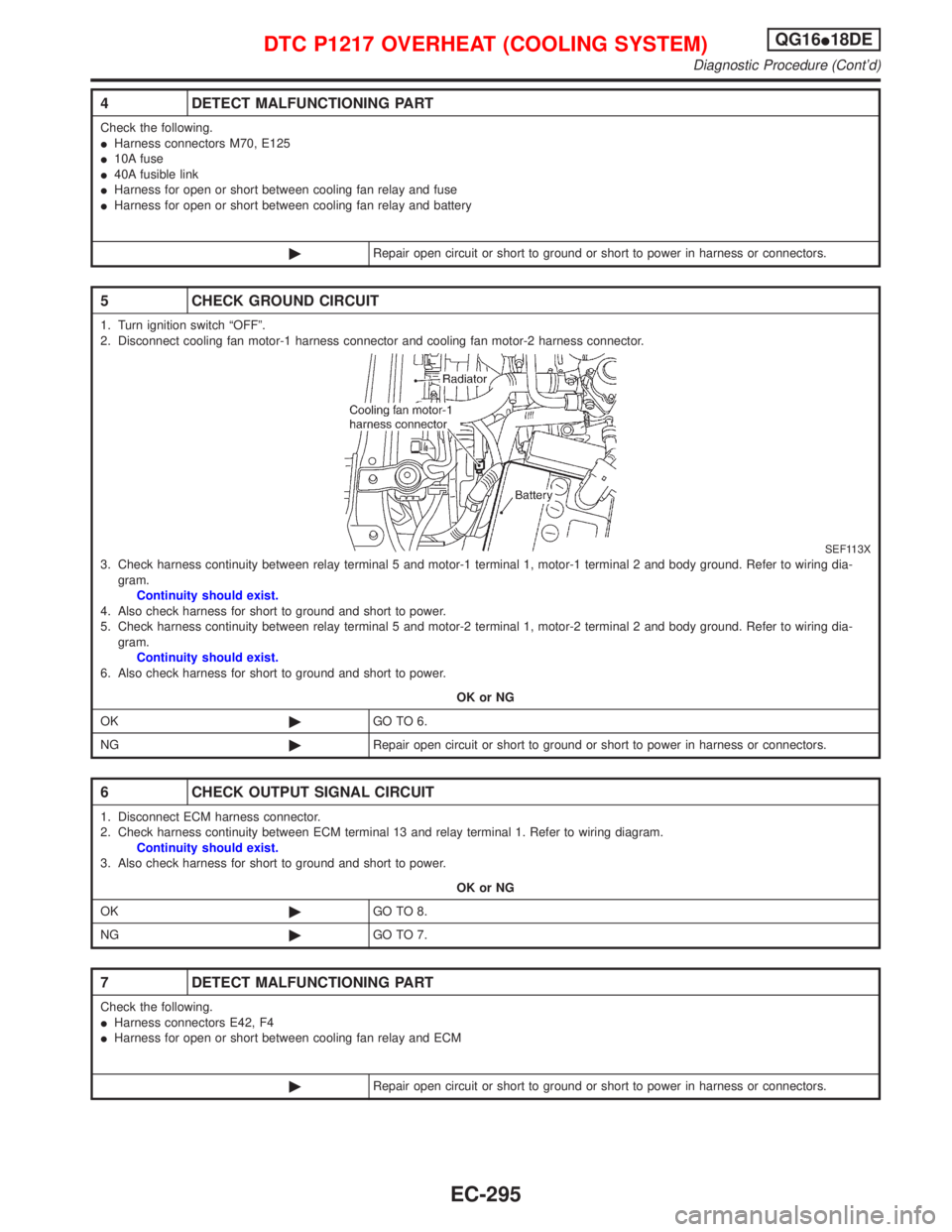
4 DETECT MALFUNCTIONING PART
Check the following.
IHarness connectors M70, E125
I10A fuse
I40A fusible link
IHarness for open or short between cooling fan relay and fuse
IHarness for open or short between cooling fan relay and battery
©Repair open circuit or short to ground or short to power in harness or connectors.
5 CHECK GROUND CIRCUIT
1. Turn ignition switch ªOFFº.
2. Disconnect cooling fan motor-1 harness connector and cooling fan motor-2 harness connector.
SEF113X3. Check harness continuity between relay terminal 5 and motor-1 terminal 1, motor-1 terminal 2 and body ground. Refer to wiring dia-
gram.
Continuity should exist.
4. Also check harness for short to ground and short to power.
5. Check harness continuity between relay terminal 5 and motor-2 terminal 1, motor-2 terminal 2 and body ground. Refer to wiring dia-
gram.
Continuity should exist.
6. Also check harness for short to ground and short to power.
OK or NG
OK©GO TO 6.
NG©Repair open circuit or short to ground or short to power in harness or connectors.
6 CHECK OUTPUT SIGNAL CIRCUIT
1. Disconnect ECM harness connector.
2. Check harness continuity between ECM terminal 13 and relay terminal 1. Refer to wiring diagram.
Continuity should exist.
3. Also check harness for short to ground and short to power.
OK or NG
OK©GO TO 8.
NG©GO TO 7.
7 DETECT MALFUNCTIONING PART
Check the following.
IHarness connectors E42, F4
IHarness for open or short between cooling fan relay and ECM
©Repair open circuit or short to ground or short to power in harness or connectors.
DTC P1217 OVERHEAT (COOLING SYSTEM)QG16I18DE
Diagnostic Procedure (Cont'd)
EC-295
Page 741 of 2267
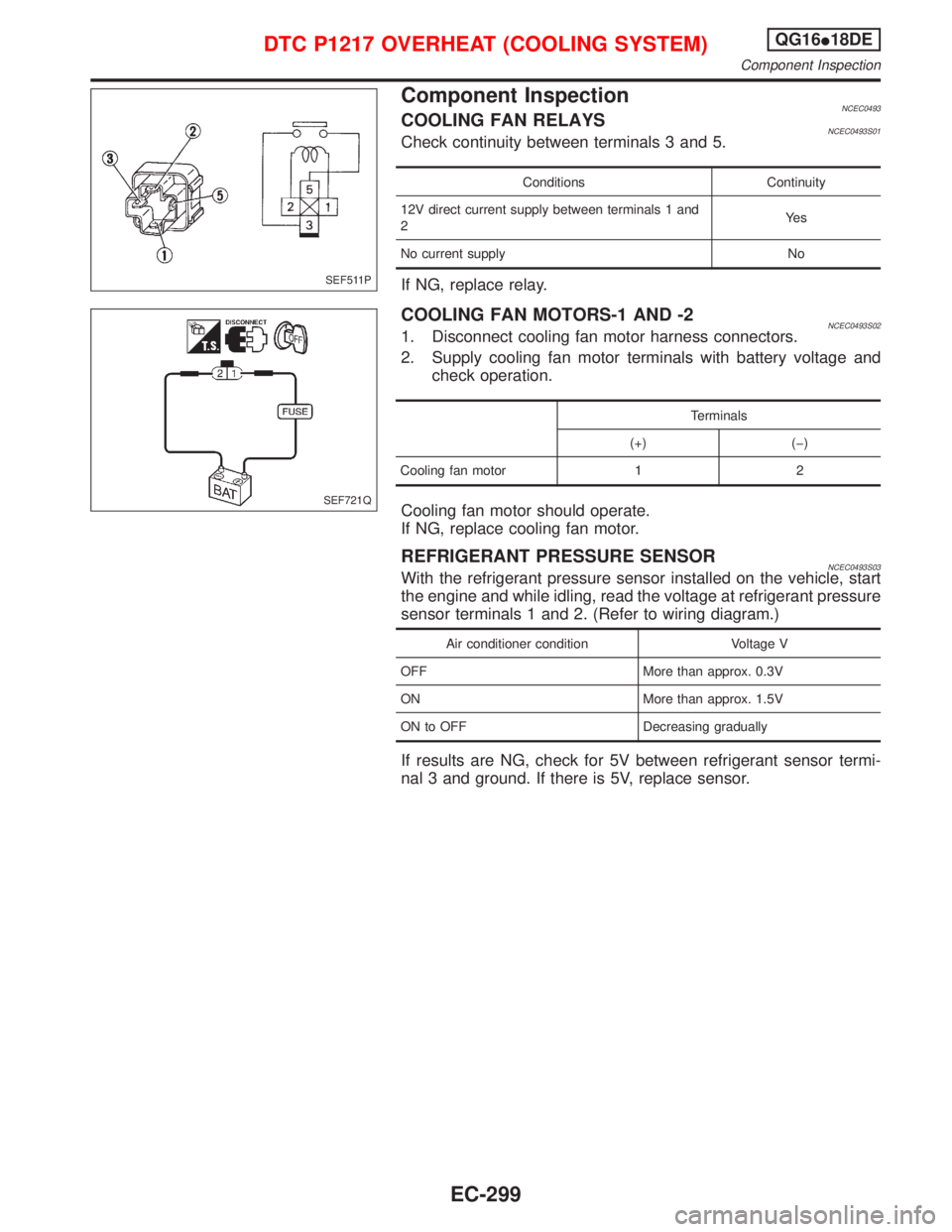
Component InspectionNCEC0493COOLING FAN RELAYSNCEC0493S01Check continuity between terminals 3 and 5.
Conditions Continuity
12V direct current supply between terminals 1 and
2Ye s
No current supply No
If NG, replace relay.
COOLING FAN MOTORS-1 AND -2NCEC0493S021. Disconnect cooling fan motor harness connectors.
2. Supply cooling fan motor terminals with battery voltage and
check operation.
Terminals
(+) (þ)
Cooling fan motor 1 2
Cooling fan motor should operate.
If NG, replace cooling fan motor.
REFRIGERANT PRESSURE SENSORNCEC0493S03With the refrigerant pressure sensor installed on the vehicle, start
the engine and while idling, read the voltage at refrigerant pressure
sensor terminals 1 and 2. (Refer to wiring diagram.)
Air conditioner condition Voltage V
OFF More than approx. 0.3V
ON More than approx. 1.5V
ON to OFF Decreasing gradually
If results are NG, check for 5V between refrigerant sensor termi-
nal 3 and ground. If there is 5V, replace sensor.
SEF511P
SEF721Q
DTC P1217 OVERHEAT (COOLING SYSTEM)QG16I18DE
Component Inspection
EC-299
Page 744 of 2267
Wiring DiagramNCEC0346
YEC074A
DTC P1401 EGR TEMPERATURE SENSOR
(IF SO EQUIPPED)QG16I18DE
Wiring Diagram
EC-302
Page 745 of 2267
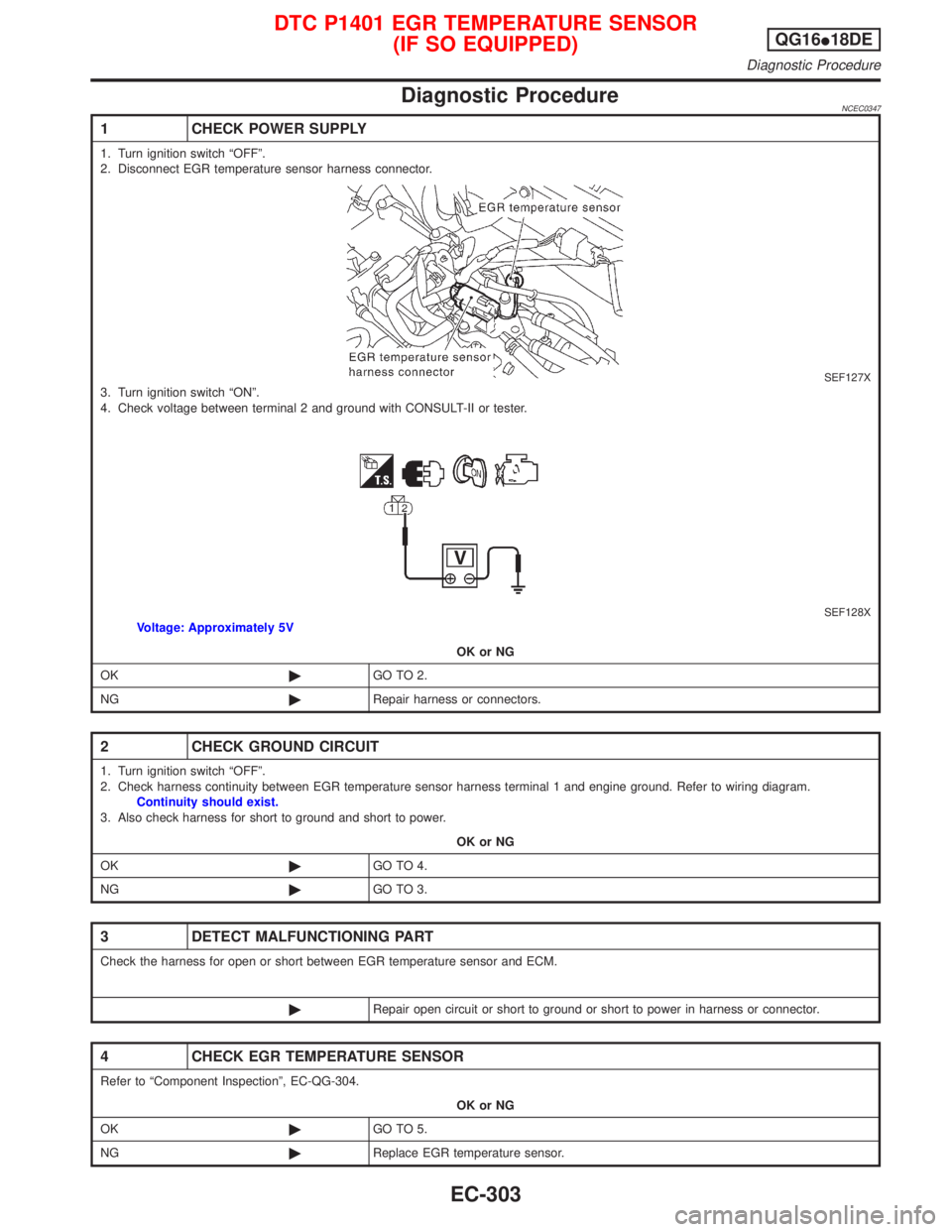
Diagnostic ProcedureNCEC0347
1 CHECK POWER SUPPLY
1. Turn ignition switch ªOFFº.
2. Disconnect EGR temperature sensor harness connector.
SEF127X3. Turn ignition switch ªONº.
4. Check voltage between terminal 2 and ground with CONSULT-II or tester.
SEF128XVoltage: Approximately 5V
OK or NG
OK©GO TO 2.
NG©Repair harness or connectors.
2 CHECK GROUND CIRCUIT
1. Turn ignition switch ªOFFº.
2. Check harness continuity between EGR temperature sensor harness terminal 1 and engine ground. Refer to wiring diagram.
Continuity should exist.
3. Also check harness for short to ground and short to power.
OK or NG
OK©GO TO 4.
NG©GO TO 3.
3 DETECT MALFUNCTIONING PART
Check the harness for open or short between EGR temperature sensor and ECM.
©Repair open circuit or short to ground or short to power in harness or connector.
4 CHECK EGR TEMPERATURE SENSOR
Refer to ªComponent Inspectionº, EC-QG-304.
OK or NG
OK©GO TO 5.
NG©Replace EGR temperature sensor.
DTC P1401 EGR TEMPERATURE SENSOR
(IF SO EQUIPPED)QG16I18DE
Diagnostic Procedure
EC-303
Page 751 of 2267
Wiring DiagramNCEC0352
YEC072A
DTC P1402 EGR FUNCTION (OPEN) (IF SO EQUIPPED)QG16I18DE
Wiring Diagram
EC-309
Page 752 of 2267
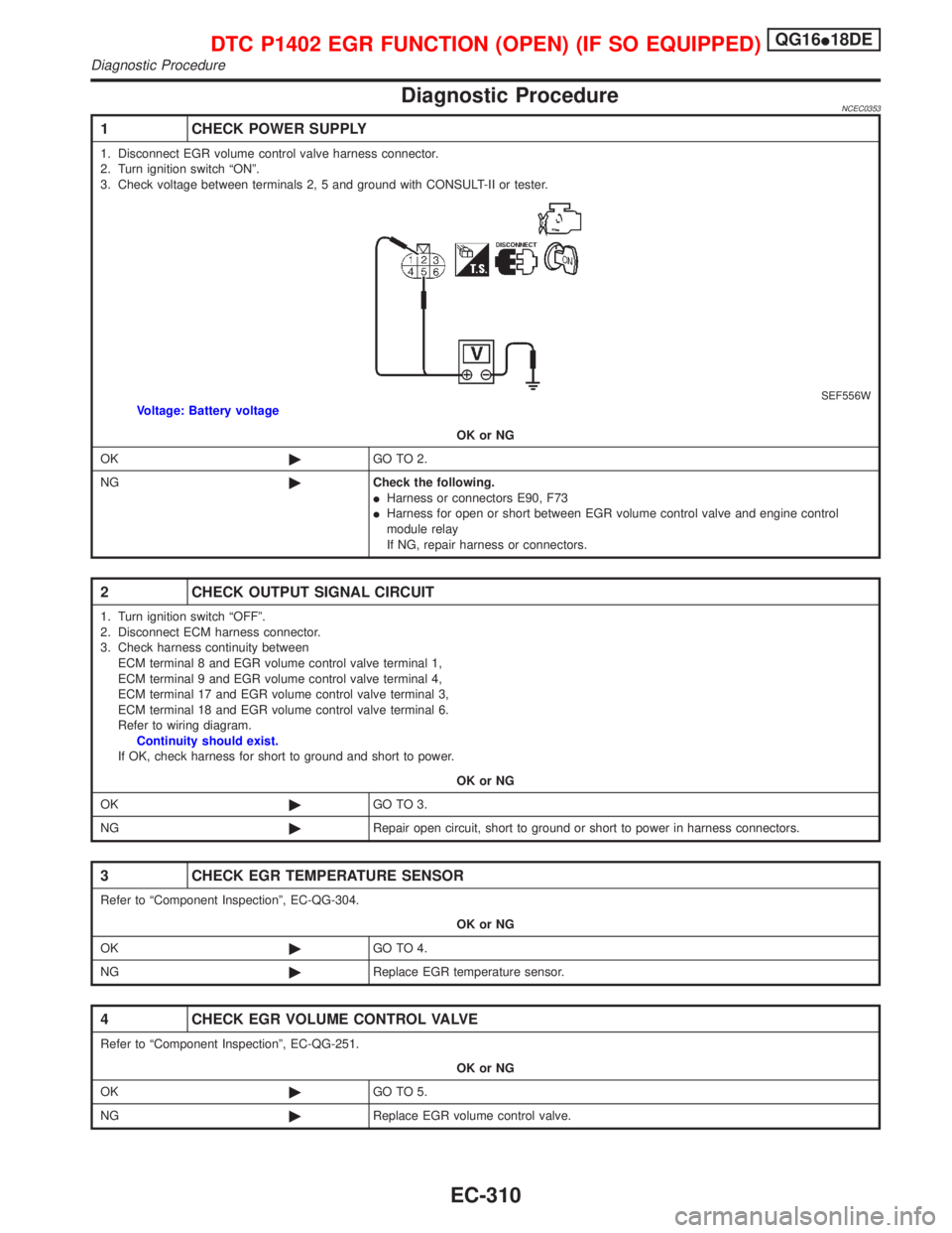
Diagnostic ProcedureNCEC0353
1 CHECK POWER SUPPLY
1. Disconnect EGR volume control valve harness connector.
2. Turn ignition switch ªONº.
3. Check voltage between terminals 2, 5 and ground with CONSULT-II or tester.
SEF556WVoltage: Battery voltage
OK or NG
OK©GO TO 2.
NG©Check the following.
IHarness or connectors E90, F73
IHarness for open or short between EGR volume control valve and engine control
module relay
If NG, repair harness or connectors.
2 CHECK OUTPUT SIGNAL CIRCUIT
1. Turn ignition switch ªOFFº.
2. Disconnect ECM harness connector.
3. Check harness continuity between
ECM terminal 8 and EGR volume control valve terminal 1,
ECM terminal 9 and EGR volume control valve terminal 4,
ECM terminal 17 and EGR volume control valve terminal 3,
ECM terminal 18 and EGR volume control valve terminal 6.
Refer to wiring diagram.
Continuity should exist.
If OK, check harness for short to ground and short to power.
OK or NG
OK©GO TO 3.
NG©Repair open circuit, short to ground or short to power in harness connectors.
3 CHECK EGR TEMPERATURE SENSOR
Refer to ªComponent Inspectionº, EC-QG-304.
OK or NG
OK©GO TO 4.
NG©Replace EGR temperature sensor.
4 CHECK EGR VOLUME CONTROL VALVE
Refer to ªComponent Inspectionº, EC-QG-251.
OK or NG
OK©GO TO 5.
NG©Replace EGR volume control valve.
DTC P1402 EGR FUNCTION (OPEN) (IF SO EQUIPPED)QG16I18DE
Diagnostic Procedure
EC-310
Page 757 of 2267
Wiring DiagramNCEC0430
YEC791
: Detectable line for DTC
: Non-detectable line for DTC
PARK/NEUTRAL
POSITION (PNP)
SWITCH
DTC P1706 PARK/NEUTRAL POSITION (PNP) SWITCHQG16I18DE
Wiring Diagram
EC-315
Page 758 of 2267
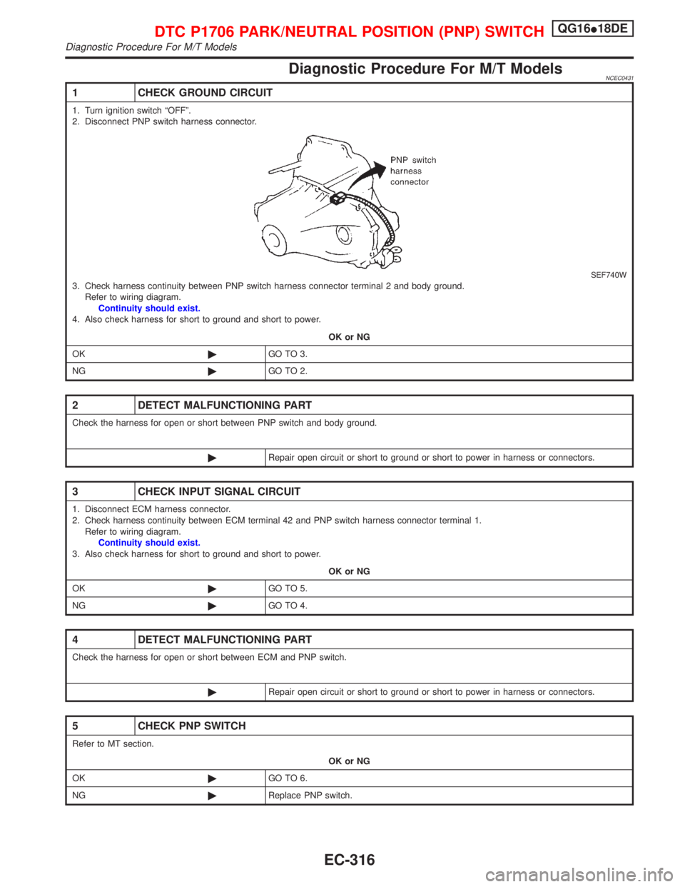
Diagnostic Procedure For M/T ModelsNCEC0431
1 CHECK GROUND CIRCUIT
1. Turn ignition switch ªOFFº.
2. Disconnect PNP switch harness connector.
SEF740W3. Check harness continuity between PNP switch harness connector terminal 2 and body ground.
Refer to wiring diagram.
Continuity should exist.
4. Also check harness for short to ground and short to power.
OK or NG
OK©GO TO 3.
NG©GO TO 2.
2 DETECT MALFUNCTIONING PART
Check the harness for open or short between PNP switch and body ground.
©Repair open circuit or short to ground or short to power in harness or connectors.
3 CHECK INPUT SIGNAL CIRCUIT
1. Disconnect ECM harness connector.
2. Check harness continuity between ECM terminal 42 and PNP switch harness connector terminal 1.
Refer to wiring diagram.
Continuity should exist.
3. Also check harness for short to ground and short to power.
OK or NG
OK©GO TO 5.
NG©GO TO 4.
4 DETECT MALFUNCTIONING PART
Check the harness for open or short between ECM and PNP switch.
©Repair open circuit or short to ground or short to power in harness or connectors.
5 CHECK PNP SWITCH
Refer to MT section.
OK or NG
OK©GO TO 6.
NG©Replace PNP switch.
DTC P1706 PARK/NEUTRAL POSITION (PNP) SWITCHQG16I18DE
Diagnostic Procedure For M/T Models
EC-316