Page 671 of 2267
Wiring DiagramNCEC0210
YEC269
Detectable line for DTC
Non-detectable line for DTC ECM
KNOCK
SENSOR
DTC P0325 KNOCK SENSOR (KS)QG16I18DE
Wiring Diagram
EC-229
Page 672 of 2267
Diagnostic ProcedureNCEC0211
1 RETIGHTEN GROUND SCREWS
Loosen and retighten engine ground screws.
SEF994W
©GO TO 2.
2 CHECK INPUT SIGNAL CIRCUIT-1
1. Turn ignition switch ªOFFº.
2. Disconnect ECM harness connector and knock sensor harness connector.
SEF056X3. Check harness continuity between knock sensor signal terminal 2 and ECM terminal 81.
Refer to wiring diagram.
Continuity should exist.
4. Also check harness for short to ground and short to power.
OK or NG
OK©GO TO 4.
NG©GO TO 3.
3 DETECT MALFUNCTIONING PART
Check the harness for open or short between knock sensor and ECM.
©Repair open circuit or short to ground or short to power in harness or connectors.
4 CHECK KNOCK SENSOR
Knock sensor
Refer to ªComponent Inspectionº, EC-QG-231.
OK or NG
OK©GO TO 5.
NG©Replace knock sensor.
View from the underside of the vehicle
Knock sensor
harness
connector
Oil filter
DTC P0325 KNOCK SENSOR (KS)QG16I18DE
Diagnostic Procedure
EC-230
Page 676 of 2267
Wiring DiagramNCEC0555
YEC070A
DTC P0335 CRANKSHAFT POSITION SENSOR (POS)QG16I18DE
Wiring Diagram
EC-234
Page 678 of 2267

3 DETECT MALFUNCTIONING PART
Check the following.
IHarness connectors E90, F73
IHarness for open or short between crankshaft position sensor and ECM relay
IHarness for open or short between crankshaft position sensor and ECM
IECM relay
©Repair open circuit or short to ground or short to power in harness or connectors.
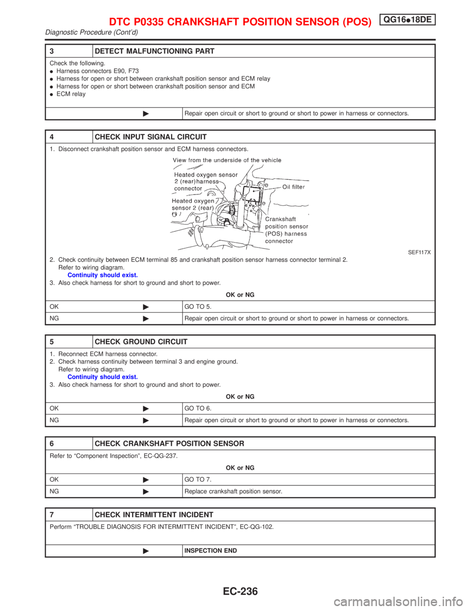
4 CHECK INPUT SIGNAL CIRCUIT
1. Disconnect crankshaft position sensor and ECM harness connectors.
SEF117X2. Check continuity between ECM terminal 85 and crankshaft position sensor harness connector terminal 2.
Refer to wiring diagram.
Continuity should exist.
3. Also check harness for short to ground and short to power.
OK or NG
OK©GO TO 5.
NG©Repair open circuit or short to ground or short to power in harness or connectors.
5 CHECK GROUND CIRCUIT
1. Reconnect ECM harness connector.
2. Check harness continuity between terminal 3 and engine ground.
Refer to wiring diagram.
Continuity should exist.
3. Also check harness for short to ground and short to power.
OK or NG
OK©GO TO 6.
NG©Repair open circuit or short to ground or short to power in harness or connectors.
6 CHECK CRANKSHAFT POSITION SENSOR
Refer to ªComponent Inspectionº, EC-QG-237.
OK or NG
OK©GO TO 7.
NG©Replace crankshaft position sensor.
7 CHECK INTERMITTENT INCIDENT
Perform ªTROUBLE DIAGNOSIS FOR INTERMITTENT INCIDENTº, EC-QG-102.
©INSPECTION END
DTC P0335 CRANKSHAFT POSITION SENSOR (POS)QG16I18DE
Diagnostic Procedure (Cont'd)
EC-236
Page 682 of 2267
Wiring DiagramNCEC0224
YEC071A
DTC P0340 CAMSHAFT POSITION SENSOR (CMPS)
(PHASE)QG16I18DE
Wiring Diagram
EC-240
Page 684 of 2267

4 DETECT MALFUNCTIONING PART
Check the following.
IHarness connectors E90, F73
IHarness for open or short between camshaft position sensor and ECM relay
IHarness for open or short between camshaft position sensor and ECM
©Repair open circuit or short to ground or short to power in harness or connectors.
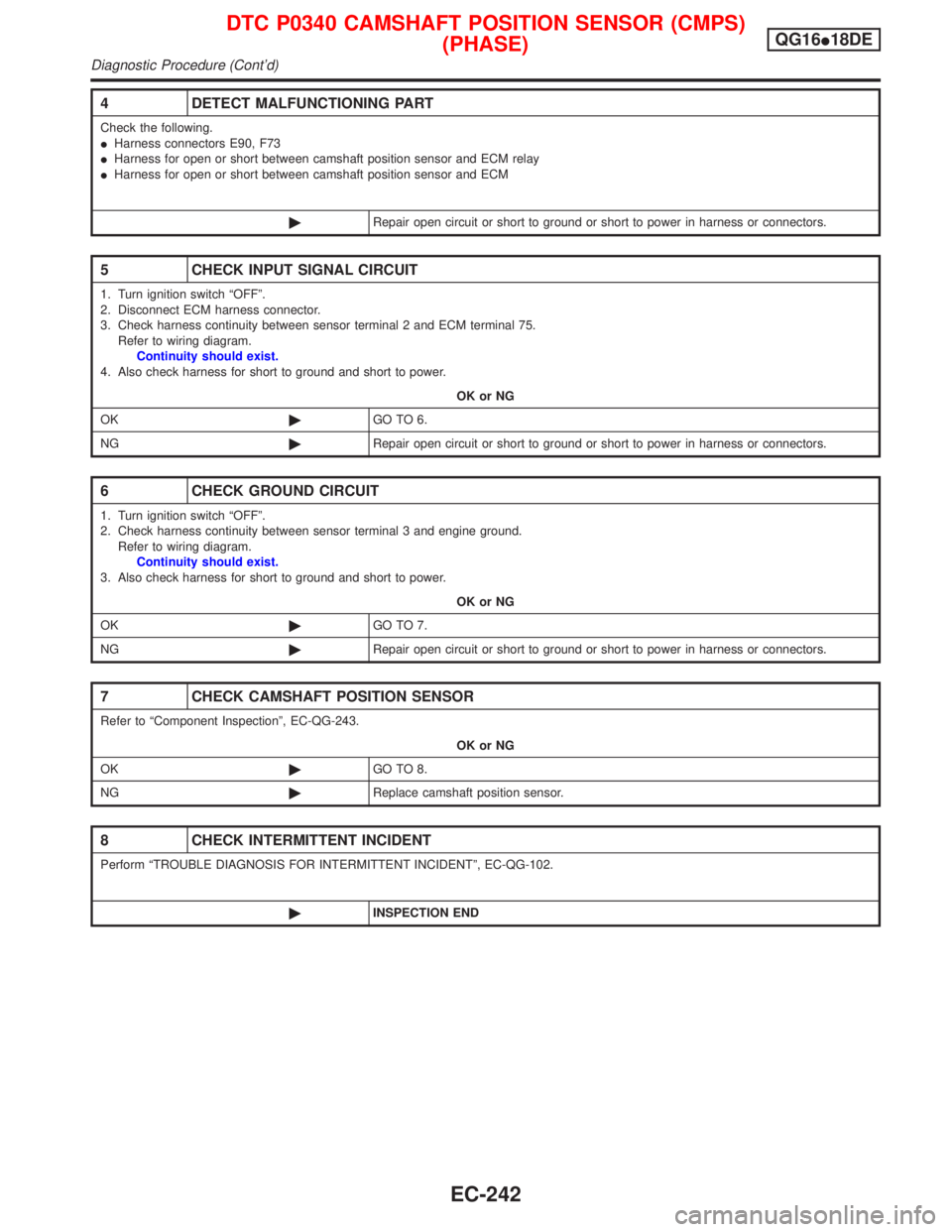
5 CHECK INPUT SIGNAL CIRCUIT
1. Turn ignition switch ªOFFº.
2. Disconnect ECM harness connector.
3. Check harness continuity between sensor terminal 2 and ECM terminal 75.
Refer to wiring diagram.
Continuity should exist.
4. Also check harness for short to ground and short to power.
OK or NG
OK©GO TO 6.
NG©Repair open circuit or short to ground or short to power in harness or connectors.
6 CHECK GROUND CIRCUIT
1. Turn ignition switch ªOFFº.
2. Check harness continuity between sensor terminal 3 and engine ground.
Refer to wiring diagram.
Continuity should exist.
3. Also check harness for short to ground and short to power.
OK or NG
OK©GO TO 7.
NG©Repair open circuit or short to ground or short to power in harness or connectors.
7 CHECK CAMSHAFT POSITION SENSOR
Refer to ªComponent Inspectionº, EC-QG-243.
OK or NG
OK©GO TO 8.
NG©Replace camshaft position sensor.
8 CHECK INTERMITTENT INCIDENT
Perform ªTROUBLE DIAGNOSIS FOR INTERMITTENT INCIDENTº, EC-QG-102.
©INSPECTION END
DTC P0340 CAMSHAFT POSITION SENSOR (CMPS)
(PHASE)QG16I18DE
Diagnostic Procedure (Cont'd)
EC-242
Page 690 of 2267
Wiring DiagramNCEC0231
YEC072A
DTC P0400 EGR FUNCTION (CLOSE) (IF SO EQUIPPED)QG16I18DE
Wiring Diagram
EC-248
Page 692 of 2267

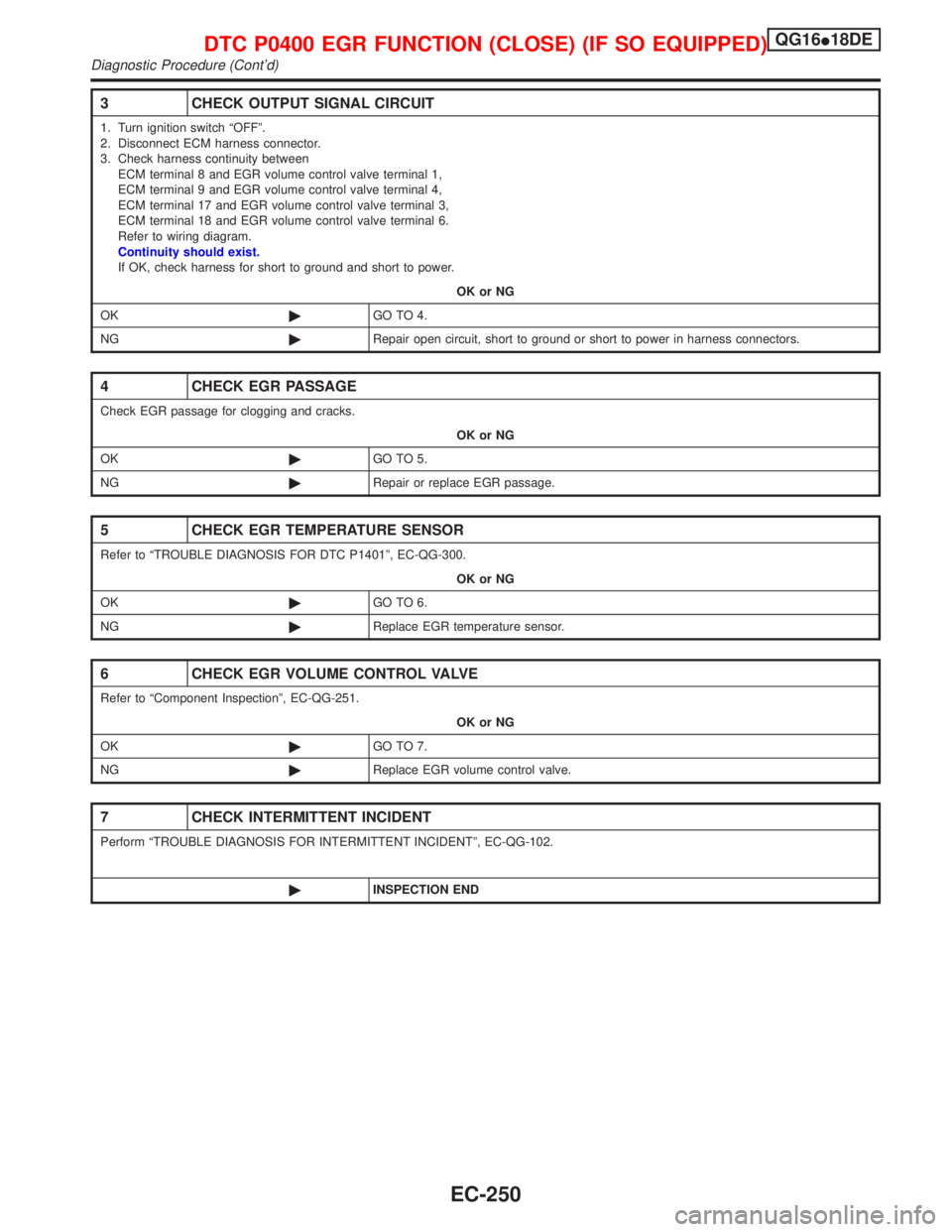
3 CHECK OUTPUT SIGNAL CIRCUIT
1. Turn ignition switch ªOFFº.
2. Disconnect ECM harness connector.
3. Check harness continuity between
ECM terminal 8 and EGR volume control valve terminal 1,
ECM terminal 9 and EGR volume control valve terminal 4,
ECM terminal 17 and EGR volume control valve terminal 3,
ECM terminal 18 and EGR volume control valve terminal 6.
Refer to wiring diagram.
Continuity should exist.
If OK, check harness for short to ground and short to power.
OK or NG
OK©GO TO 4.
NG©Repair open circuit, short to ground or short to power in harness connectors.
4 CHECK EGR PASSAGE
Check EGR passage for clogging and cracks.
OK or NG
OK©GO TO 5.
NG©Repair or replace EGR passage.
5 CHECK EGR TEMPERATURE SENSOR
Refer to ªTROUBLE DIAGNOSIS FOR DTC P1401º, EC-QG-300.
OK or NG
OK©GO TO 6.
NG©Replace EGR temperature sensor.
6 CHECK EGR VOLUME CONTROL VALVE
Refer to ªComponent Inspectionº, EC-QG-251.
OK or NG
OK©GO TO 7.
NG©Replace EGR volume control valve.
7 CHECK INTERMITTENT INCIDENT
Perform ªTROUBLE DIAGNOSIS FOR INTERMITTENT INCIDENTº, EC-QG-102.
©INSPECTION END
DTC P0400 EGR FUNCTION (CLOSE) (IF SO EQUIPPED)QG16I18DE
Diagnostic Procedure (Cont'd)
EC-250