1999 NISSAN PRIMERA diagram
[x] Cancel search: diagramPage 1974 of 2267
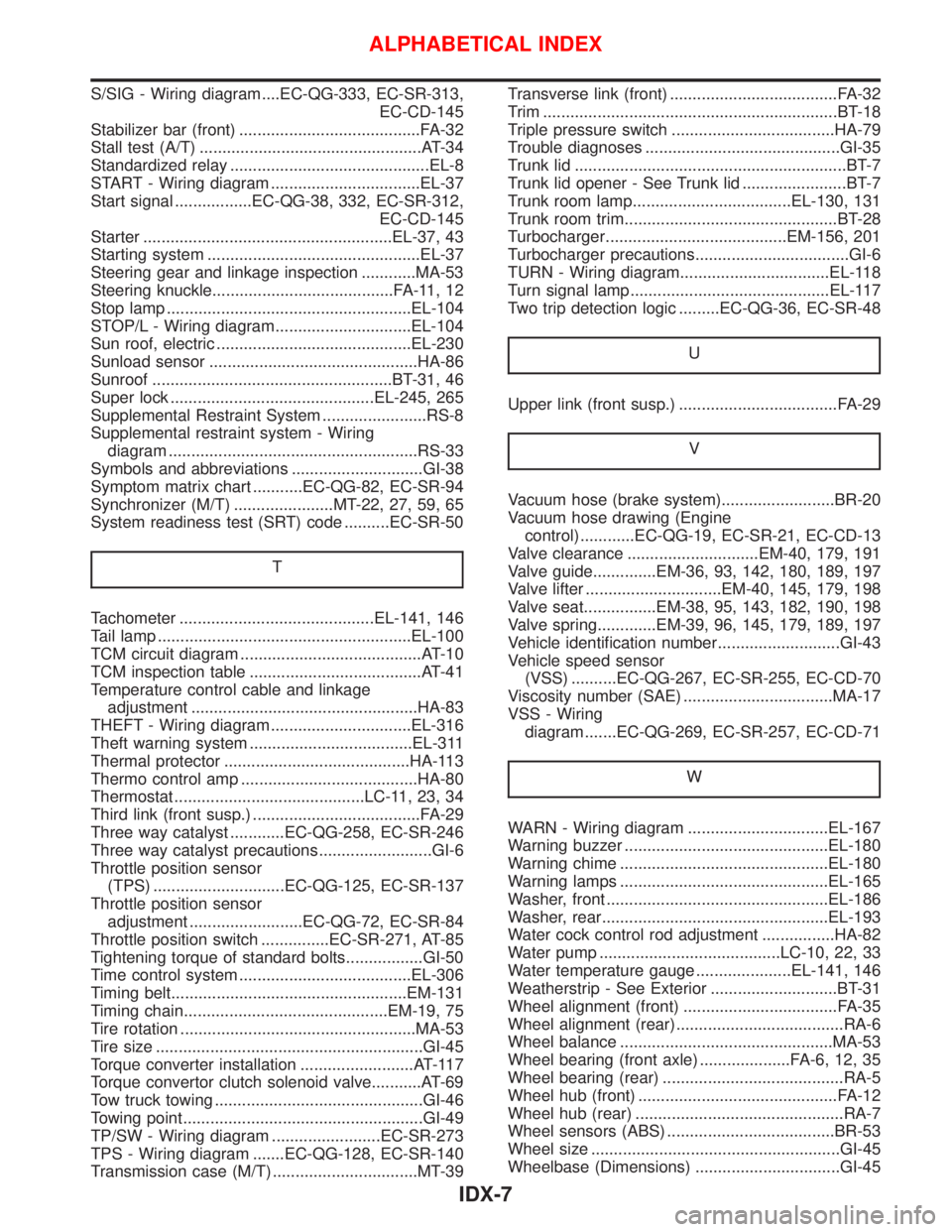
S/SIG - Wiring diagram ....EC-QG-333, EC-SR-313,
EC-CD-145
Stabilizer bar (front) ........................................FA-32
Stall test (A/T) .................................................AT-34
Standardized relay ............................................EL-8
START - Wiring diagram .................................EL-37
Start signal .................EC-QG-38, 332, EC-SR-312,
EC-CD-145
Starter .......................................................EL-37, 43
Starting system ...............................................EL-37
Steering gear and linkage inspection ............MA-53
Steering knuckle........................................FA-11, 12
Stop lamp ......................................................EL-104
STOP/L - Wiring diagram..............................EL-104
Sun roof, electric ...........................................EL-230
Sunload sensor ..............................................HA-86
Sunroof .....................................................BT-31, 46
Super lock .............................................EL-245, 265
Supplemental Restraint System .......................RS-8
Supplemental restraint system - Wiring
diagram .......................................................RS-33
Symbols and abbreviations .............................GI-38
Symptom matrix chart ...........EC-QG-82, EC-SR-94
Synchronizer (M/T) ......................MT-22, 27, 59, 65
System readiness test (SRT) code ..........EC-SR-50
T
Tachometer ...........................................EL-141, 146
Tail lamp ........................................................EL-100
TCM circuit diagram ........................................AT-10
TCM inspection table ......................................AT-41
Temperature control cable and linkage
adjustment ..................................................HA-83
THEFT - Wiring diagram ...............................EL-316
Theft warning system ....................................EL-311
Thermal protector .........................................HA-113
Thermo control amp .......................................HA-80
Thermostat ..........................................LC-11, 23, 34
Third link (front susp.) .....................................FA-29
Three way catalyst ............EC-QG-258, EC-SR-246
Three way catalyst precautions.........................GI-6
Throttle position sensor
(TPS) .............................EC-QG-125, EC-SR-137
Throttle position sensor
adjustment .........................EC-QG-72, EC-SR-84
Throttle position switch ...............EC-SR-271, AT-85
Tightening torque of standard bolts.................GI-50
Time control system ......................................EL-306
Timing belt....................................................EM-131
Timing chain.............................................EM-19, 75
Tire rotation ....................................................MA-53
Tire size ...........................................................GI-45
Torque converter installation .........................AT-117
Torque convertor clutch solenoid valve...........AT-69
Tow truck towing ..............................................GI-46
Towing point.....................................................GI-49
TP/SW - Wiring diagram ........................EC-SR-273
TPS - Wiring diagram .......EC-QG-128, EC-SR-140
Transmission case (M/T) ................................MT-39Transverse link (front) .....................................FA-32
Trim .................................................................BT-18
Triple pressure switch ....................................HA-79
Trouble diagnoses ...........................................GI-35
Trunk lid ............................................................BT-7
Trunk lid opener - See Trunk lid .......................BT-7
Trunk room lamp...................................EL-130, 131
Trunk room trim...............................................BT-28
Turbocharger........................................EM-156, 201
Turbocharger precautions..................................GI-6
TURN - Wiring diagram.................................EL-118
Turn signal lamp............................................EL-117
Two trip detection logic .........EC-QG-36, EC-SR-48
U
Upper link (front susp.) ...................................FA-29
V
Vacuum hose (brake system).........................BR-20
Vacuum hose drawing (Engine
control) ............EC-QG-19, EC-SR-21, EC-CD-13
Valve clearance .............................EM-40, 179, 191
Valve guide..............EM-36, 93, 142, 180, 189, 197
Valve lifter ..............................EM-40, 145, 179, 198
Valve seat................EM-38, 95, 143, 182, 190, 198
Valve spring.............EM-39, 96, 145, 179, 189, 197
Vehicle identification number...........................GI-43
Vehicle speed sensor
(VSS) ..........EC-QG-267, EC-SR-255, EC-CD-70
Viscosity number (SAE) .................................MA-17
VSS - Wiring
diagram .......EC-QG-269, EC-SR-257, EC-CD-71
W
WARN - Wiring diagram ...............................EL-167
Warning buzzer .............................................EL-180
Warning chime ..............................................EL-180
Warning lamps ..............................................EL-165
Washer, front .................................................EL-186
Washer, rear..................................................EL-193
Water cock control rod adjustment ................HA-82
Water pump ........................................LC-10, 22, 33
Water temperature gauge .....................EL-141, 146
Weatherstrip - See Exterior ............................BT-31
Wheel alignment (front) ..................................FA-35
Wheel alignment (rear).....................................RA-6
Wheel balance ...............................................MA-53
Wheel bearing (front axle) ....................FA-6, 12, 35
Wheel bearing (rear) ........................................RA-5
Wheel hub (front) ............................................FA-12
Wheel hub (rear) ..............................................RA-7
Wheel sensors (ABS) .....................................BR-53
Wheel size .......................................................GI-45
Wheelbase (Dimensions) ................................GI-45
ALPHABETICAL INDEX
IDX-7
Page 1975 of 2267
Wide open & closed throttle position
switch.............................EC-QG-125, EC-SR-137
Width (Dimensions) .........................................GI-45
WINDOW - Wiring diagram ..........................EL-240
Windshield.......................................................BT-53
WIP/R - Wiring diagram ................................EL-195Wiper and washer .........................................EL-188
Wiper, front....................................................EL-186
Wiper, rear ....................................................EL-193
Wiring diagrams ...............................................GI-11
ALPHABETICAL INDEX
IDX-8
Page 2184 of 2267
RESTRAINT SYSTEM
SECTION
RS
CONTENTS
PRECAUTION................................................................ 2
Supplemental Restraint System (SRS)²AIR
BAG²and²SEAT BELT PRE-TENSIONER²............. 2
SEAT BELT.................................................................... 3
Front Seat Belt........................................................... 3
Rear Seat Belt (4-door models) ................................ 4
Rear Seat Belt (Wagon and 5-door models)............. 6
SUPPLEMENTAL RESTRAINT SYSTEM (SRS).......... 8
Precautions for SRS²AIR BAG²and²SEAT
BELT PRE-TENSIONER²Service ............................. 8
Special Service Tools ................................................ 8
Description ............................................................... 10
SRS Component Parts Location .............................. 11
Maintenance Items .................................................. 12
Removal and Installation - Diagnosis Sensor
Unit, Seat Belt Pre-tensioner and Satellite
Sensor...................................................................... 13
Removal - Air Bag Module and Spiral Cable .......... 14
Installation - Air Bag Module and Spiral Cable ....... 16Removal - Front Passenger's Air Bag Module ........ 17
Installation - Front Passenger's Air Bag Module ..... 18
Removal - Side Air Bag Module .............................. 19
Installation - Side Air Bag Module ........................... 20
Disposal of Air Bag Module and Seat Belt Pre-
tensioner .................................................................. 22
TROUBLE DIAGNOSES - SUPPLEMENTAL
RESTRAINT SYSTEM (SRS)...................................... 28
Trouble Diagnoses Introduction............................... 28
How to Perform Trouble Diagnoses for Quick
and Accurate Repair ................................................ 30
Schematic ................................................................ 32
Wiring Diagram - SRS -........................................... 33
SRS-Operation Check ............................................. 37
Trouble Diagnoses with CONSULT-II................. 38
Trouble Diagnoses without CONSULT-II............ 48
Trouble Diagnoses for Air Bag Warning Lamp........ 56
COLLISION DIAGNOSIS............................................. 57
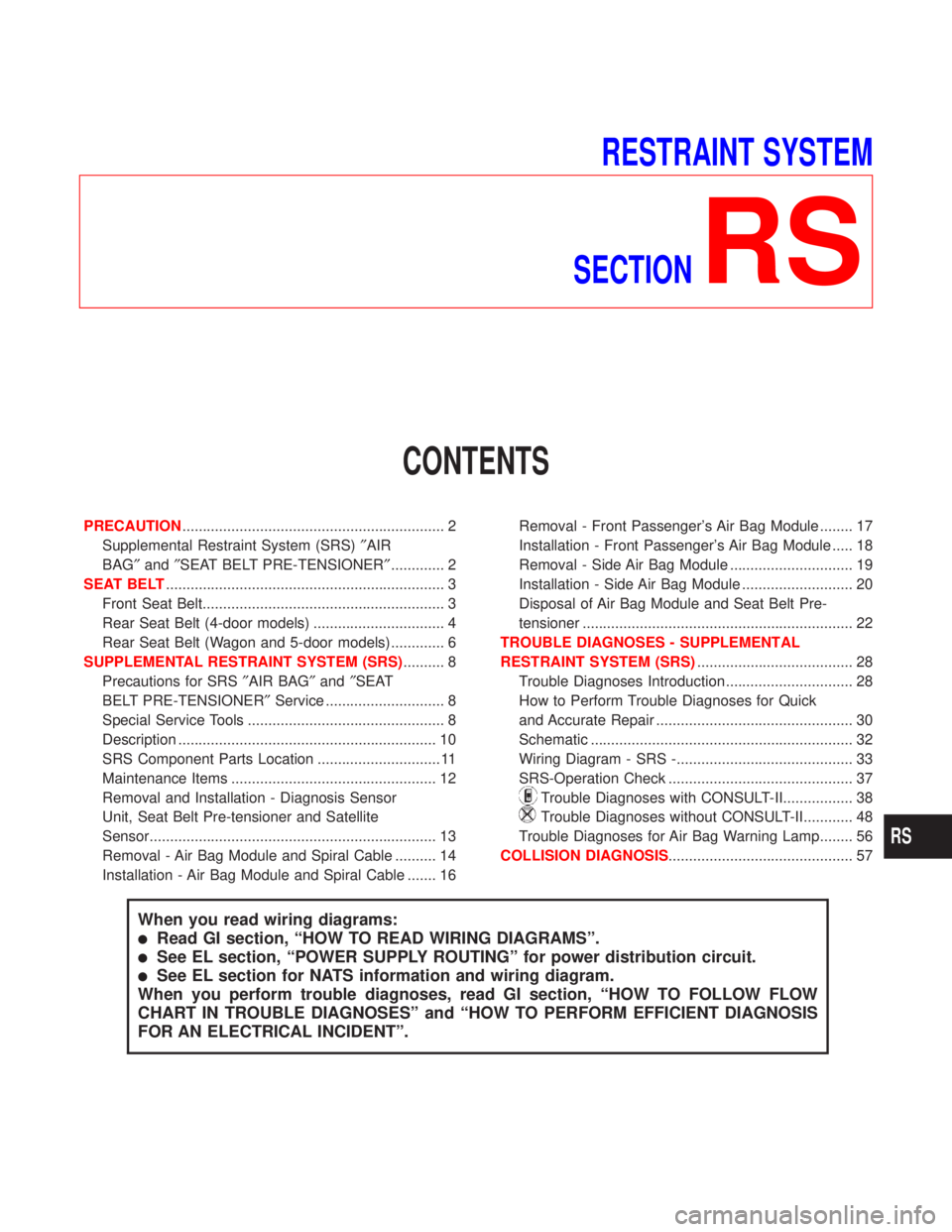
When you read wiring diagrams:
lRead GI section, ªHOW TO READ WIRING DIAGRAMSº.
lSee EL section, ªPOWER SUPPLY ROUTINGº for power distribution circuit.
lSee EL section for NATS information and wiring diagram.
When you perform trouble diagnoses, read GI section, ªHOW TO FOLLOW FLOW
CHART IN TROUBLE DIAGNOSESº and ªHOW TO PERFORM EFFICIENT DIAGNOSIS
FOR AN ELECTRICAL INCIDENTº.
RS
Page 2216 of 2267
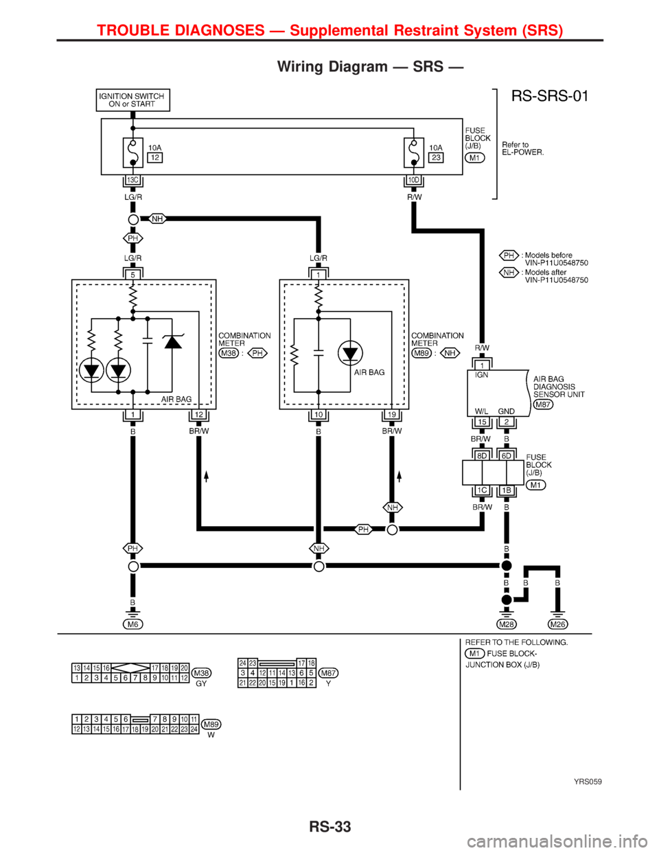
Wiring Diagram Ð SRS Ð
YRS059
TROUBLE DIAGNOSES Ð Supplemental Restraint System (SRS)
RS-33
Page 2217 of 2267
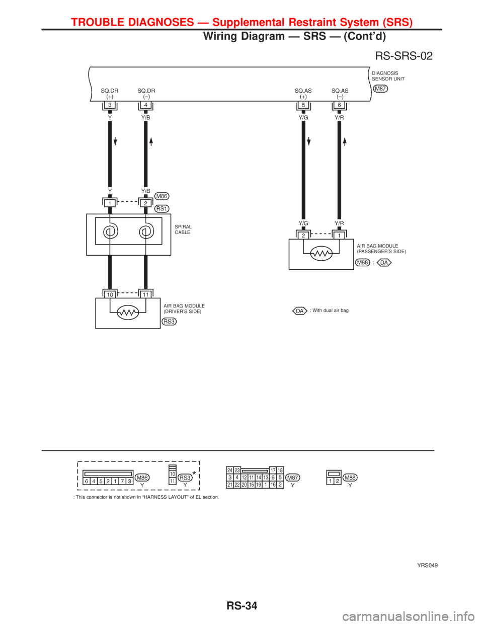
YRS049
DIAGNOSIS
SENSOR UNIT
SPIRAL
CABLE
AIR BAG MODULE
(DRIVER'S SIDE)AIR BAG MODULE
(PASSENGER'S SIDE)
: With dual air bag
: This connector is not shown in ªHARNESS LAYOUTº of EL section.
TROUBLE DIAGNOSES Ð Supplemental Restraint System (SRS)
Wiring Diagram Ð SRS Ð (Cont'd)
RS-34
Page 2218 of 2267
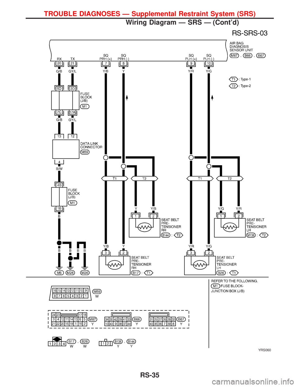
YRS060
TROUBLE DIAGNOSES Ð Supplemental Restraint System (SRS)
Wiring Diagram Ð SRS Ð (Cont'd)
RS-35
Page 2219 of 2267
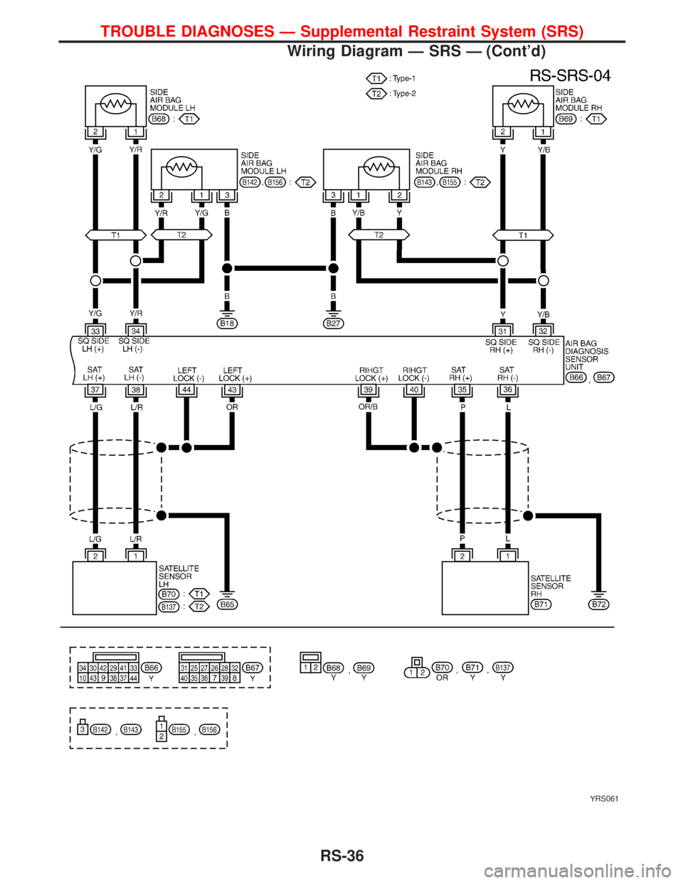
YRS061
TROUBLE DIAGNOSES Ð Supplemental Restraint System (SRS)
Wiring Diagram Ð SRS Ð (Cont'd)
RS-36