1999 NISSAN PRIMERA diagram
[x] Cancel search: diagramPage 1815 of 2267
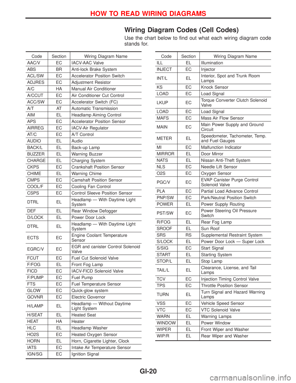
Wiring Diagram Codes (Cell Codes)
Use the chart below to find out what each wiring diagram code
stands for.
Code Section Wiring Diagram Name
AAC/V EC IACV-AAC Valve
ABS BR Anti-lock Brake System
ACL/SW EC Accelerator Position Switch
ADJRES EC Adjustment Resistor
A/C HA Manual Air Conditioner
A/CCUT EC Air Conditioner Cut Control
ACC/SW EC Accelerator Switch (FC)
A/T AT Automatic Transmission
AIM EL Headlamp Aiming Control
APS EC Accelerator Position Sensor
AIRREG EC IACV-Air Regulator
AT/C EC A/T Control
AUDIO EL Audio
BACK/L EL Back-up Lamp
BUZZER EL Warning Buzzer
CHARGE EL Charging System
CKPS EC Crankshaft Position Sensor
CHIME EL Warning Chime
CMPS EC Camshaft Position Sensor
COOL/F EC Cooling Fan Control
CSPS EC Control Sleeve Position Sensor
DTRL ELHeadlamp Ð With Daytime Light
System
DEF EL Rear Window Defogger
D/LOCK EL Power Door Lock
DTRL ELHeadlamp Ð With Daytime Light
System
ECTS ECEngine Coolant Temperature
Sensor
EGRC/V ECEGR and canister Control Solenoid
Valve
FCUT EC Fuel Cut Solenoid Valve
F/FOG EL Front Fog Lamp
FICD EC IACV-FICD Solenoid Valve
F/PUMP EC Fuel Pump
FTS EC Fuel Temperature Sensor
GLOW EC Quick-glow system
GOVNR EC Electric Governor
H/LAMP ELHeadlamp Ð Without Daytime
Light System
H/SEAT EL Heated Seat
HEAT HA Heater
HLC EL Headlamp Washer
HO2S EC Heated Oxygen Sensor
HORN EL Horn, Cigarette Lighter, Clock
IATS EC Intake Air Temperature Sensor
IGN/SG EC Ignition SignalCode Section Wiring Diagram Name
ILL EL Illumination
INJECT EC Injector
INT/L ELInterior, Spot and Trunk Room
Lamps
KS EC Knock Sensor
LOAD EC Load Signal
LKUP ECTorque Converter Clutch Solenoid
Valve
LOAD EC Load Signal
MAFS EC Mass Air Flow Sensor
MAIN ECMain Power Supply and Ground
Circuit
METER ELSpeedometer, Tachometer, Temp.
and Fuel Gauges
MI EC Malfunction Indicator
MIRROR EL Door Mirror
NATS EL Nissan Anti-Theft System
NLS EC Needle Lift Sensor
O2S EC Oxygen Sensor
PGC/V ECEVAP Canister Purge Control
Solenoid Valve
PLA EC Partial Load Advance Control
PNP/SW EC Park/Neutral Position Switch
POWER EL Power Supply Routing
PST/SW ECPower Steering Oil Pressure
Switch
R/FOG EL Rear Fog Lamp
SROOF EL Sun Roof
SRS RS Supplemental Restraint System
S/LOCK EL Power Door Lock Ð Super Lock
S/SIG EC Start Signal
START EL Starting System
STOP/L EL Stop Lamp
TAIL/L ELClearance, License, and Tail
Lamps
TCV EC Injection Timing Control Valve
TPS EC Throttle Position Sensor
TURN ELTurn Signal and Hazard Warning
Lamps
VSS EC Vehicle Speed Sensor
VTC EC VTC Solenoid Valve
WARN EL Warning Lamps
WINDOW EL Power Window
WIPER EL Front Wiper and Washer
WIP/R EL Rear Wiper and Washer
HOW TO READ WIRING DIAGRAMS
GI-20
Page 1822 of 2267
Engine compartment
There are several reasons a vehicle or engine vibration could
cause an electrical complaint. Some of the things to check for
are:
lConnectors not fully seated.
lWiring harness not long enough and is being stressed due
to engine vibrations or rocking.
lWires laying across brackets or moving components.
lLoose, dirty or corroded ground wires.
lWires routed too close to hot components.
To inspect components under the hood, start by verifying the
integrity of ground connections. (Refer to GROUND INSPEC-
TION described later.) First check that the system is properly
grounded. Then check for loose connection bygently shaking
the wiring or components as previously explained. Using the
wiring diagrams inspect the wiring for continuity.
Behind the instrument panel
An improperly routed or improperly clamped harness can
become pinched during accessory installation. Vehicle vibration
can aggravate a harness which is routed along a bracket or near
a screw.
Under seating areas
An unclamped or loose harness can cause wiring to be pinched
by seat components (such as slide guides) during vehicle vibra-
tion. If the wiring runs under seating areas, inspect wire routing
for possible damage or pinching.
HEAT SENSITIVE
The owner's problem may occur during hot weather or after car
has sat for a short time. In such cases you will want to check for
a heat sensitive condition.
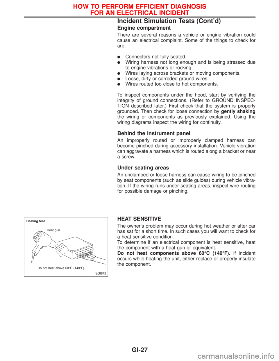
To determine if an electrical component is heat sensitive, heat
the component with a heat gun or equivalent.
Do not heat components above 60ÉC (140ÉF).If incident
occurs while heating the unit, either replace or properly insulate
the component.
SGI842 Heating test
Heat gun
Do not heat above 60ÉC (140ÉF).
HOW TO PERFORM EFFICIENT DIAGNOSIS
FOR AN ELECTRICAL INCIDENT
Incident Simulation Tests (Cont'd)
GI-27
Page 1830 of 2267
NOTICE
Trouble diagnoses indicates work procedures required to diag-
nose problems effectively. Observe the following instructions
before diagnosing.
1) Before performing trouble diagnoses, read the ªPrelimi-
nary Checkº, the ªSymptom Chartº or the ªWork Flowº.
2) After repairs, re-check that the problem has been com-
pletely eliminated.
3) Refer to Component Parts and Harness Connector Loca-
tion for the Systems described in each section for
identification/location of components and harness con-
nectors.
4) Refer to the Circuit Diagram for Quick Pinpoint Check.
If you need to check circuit continuity between harness
connectors in more detail, such as when a sub-harness
is used, refer to Wiring Diagram in each individual sec-
tion and Harness Layout in EL section for identification
of harness connectors.
5) When checking circuit continuity, ignition switch should
be in the ªLOCKº position.
6) Before checking voltage at connectors, check battery
voltage.
7) After accomplishing the Diagnostic Procedures and
Electrical Components Inspection, make sure that all
harness connectors are reconnected as they were.
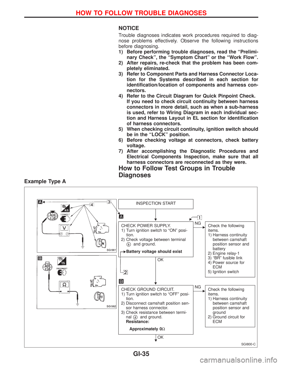
How to Follow Test Groups in Trouble
Diagnoses
Example Type A
SGI800-C
INSPECTION START
CHECK POWER SUPPLY.
1) Turn ignition switch to ªONº posi-
tion.
2) Check voltage between terminal
pband ground.
Battery voltage should exist
OK
ENG
Check the following
items.
1) Harness continuity
between camshaft
position sensor and
battery
2) Engine relay-1
3) ªBRº fusible link
4) Power source for
ECM
5) Ignition switch
CHECK GROUND CIRCUIT.
1) Turn ignition switch to ªOFFº posi-
tion.
2) Disconnect camshaft position sen-
sor harness connector.
3) Check resistance between termi-
nal
pdand ground.
Resistance:
Approximately 0W
OK
ENG
Check the following
items.
1) Harness continuity
between camshaft
position sensor and
ground
2) Ground circuit for
ECM
H
H
H
HOW TO FOLLOW TROUBLE DIAGNOSES
GI-35
Page 1835 of 2267
NOTE:
lThe CONSULT-II must be used in conjunction with a program card.
CONSULT-II does not require loading (Initialisation) procedure.
lBe sure the CONSULT-II is turned off before installing or removing a program card.
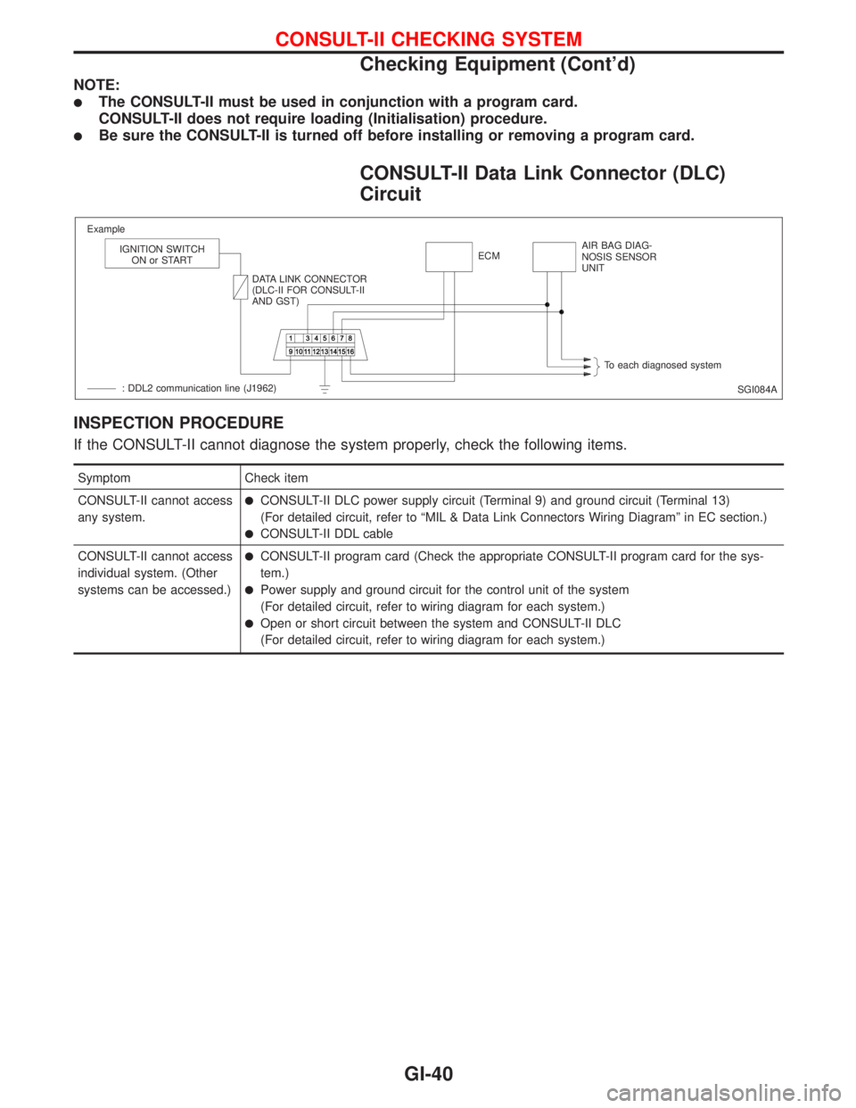
CONSULT-II Data Link Connector (DLC)
Circuit
INSPECTION PROCEDURE
If the CONSULT-II cannot diagnose the system properly, check the following items.
Symptom Check item
CONSULT-II cannot access
any system.
lCONSULT-II DLC power supply circuit (Terminal 9) and ground circuit (Terminal 13)
(For detailed circuit, refer to ªMIL & Data Link Connectors Wiring Diagramº in EC section.)
lCONSULT-II DDL cable
CONSULT-II cannot access
individual system. (Other
systems can be accessed.)
lCONSULT-II program card (Check the appropriate CONSULT-II program card for the sys-
tem.)
lPower supply and ground circuit for the control unit of the system
(For detailed circuit, refer to wiring diagram for each system.)
lOpen or short circuit between the system and CONSULT-II DLC
(For detailed circuit, refer to wiring diagram for each system.)
SGI084A Example
IGNITION SWITCH
ON or START
DATA LINK CONNECTOR
(DLC-II FOR CONSULT-II
AND GST)ECMAIR BAG DIAG-
NOSIS SENSOR
UNIT
To each diagnosed system
: DDL2 communication line (J1962)
CONSULT-II CHECKING SYSTEM
Checking Equipment (Cont'd)
GI-40
Page 1850 of 2267
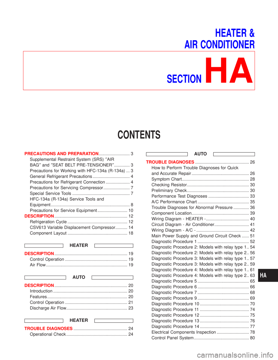
HEATER &
AIR CONDITIONER
SECTION
HA
CONTENTS
PRECAUTIONS AND PREPARATION.......................... 3
Supplemental Restraint System (SRS)²AIR
BAG²and²SEAT BELT PRE-TENSIONER²............. 3
Precautions for Working with HFC-134a (R-134a) ... 3
General Refrigerant Precautions ............................... 4
Precautions for Refrigerant Connection .................... 4
Precautions for Servicing Compressor ...................... 7
Special Service Tools ................................................ 7
HFC-134a (R-134a) Service Tools and
Equipment .................................................................. 8
Precautions for Service Equipment ......................... 10
DESCRIPTION............................................................. 12
Refrigeration Cycle .................................................. 12
CSV613 Variable Displacement Compressor.......... 14
Component Layout .................................................. 18
HEATER
DESCRIPTION............................................................. 19
Control Operation .................................................... 19
Air Flow .................................................................... 19
AUTO
DESCRIPTION............................................................. 20
Introduction .............................................................. 20
Features ................................................................... 20
Control Operation .................................................... 21
Discharge Air Flow................................................... 23
HEATER
TROUBLE DIAGNOSES............................................. 24
Operational Check ................................................... 24
AUTO
TROUBLE DIAGNOSES............................................. 26
How to Perform Trouble Diagnoses for Quick
and Accurate Repair ................................................ 26
Symptom Chart ........................................................ 28
Checking Resistor.................................................... 30
Preliminary Check.................................................... 30
Performance Test Diagnoses .................................. 33
A/C Performance Chart ........................................... 35
Trouble Diagnoses for Abnormal Pressure ............. 36
Component Location................................................ 39
Wiring Diagram - HEATER -.................................... 40
Circuit Diagram - Air Conditioner............................. 41
Wiring Diagram - A/C - ............................................ 42
Main Power Supply and Ground Circuit Check ...... 51
Diagnostic Procedure 1 ........................................... 52
Diagnostic Procedure 2: Models with relay type 1.. 54
Diagnostic Procedure 2: Models with relay type 2.. 56
Diagnostic Procedure 3: Models with relay type 1.. 57
Diagnostic Procedure 3: Models with relay type 2.. 59
Diagnostic Procedure 4: Models with relay type 1.. 61
Diagnostic Procedure 4: Models with relay type 2.. 63
Diagnostic Procedure 5 ........................................... 65
Diagnostic Procedure 6 ........................................... 66
Diagnostic Procedure 7 ........................................... 68
Diagnostic Procedure 9 ........................................... 69
Diagnostic Procedure 10 ......................................... 70
Diagnostic Procedure 11 ......................................... 74
Diagnostic Procedure 12 ......................................... 75
Diagnostic Procedure 13 ......................................... 76
Diagnostic Procedure 14 ......................................... 77
Electrical Components Inspection ........................... 78
Control Panel System .............................................. 80
HA
Page 1870 of 2267
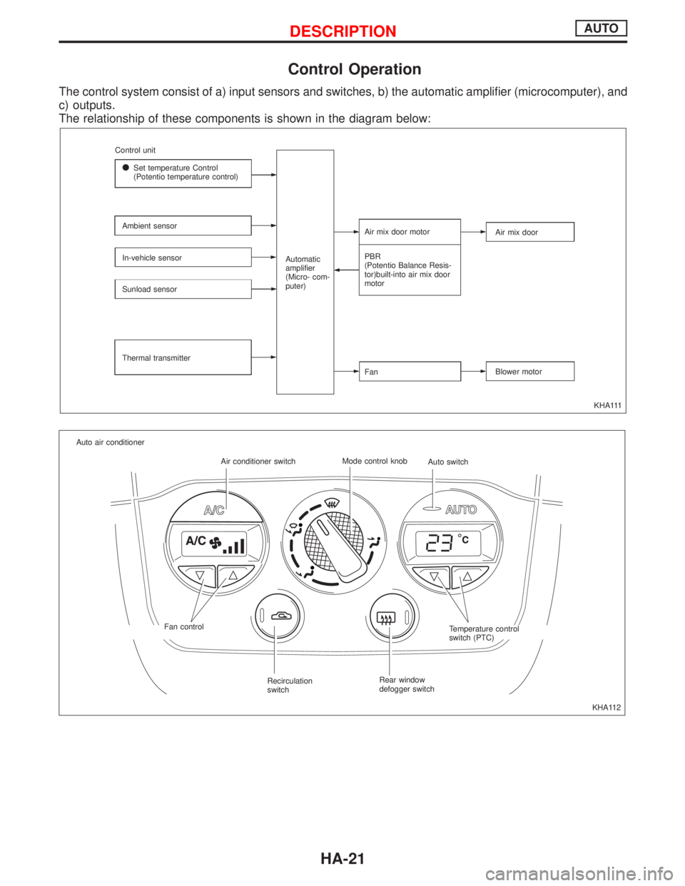
Control Operation
The control system consist of a) input sensors and switches, b) the automatic amplifier (microcomputer), and
c) outputs.
The relationship of these components is shown in the diagram below:
KHA111 Control unit
lSet temperature Control
(Potentio temperature control)
Ambient sensor
In-vehicle sensor
Sunload sensor
Thermal transmitterAutomatic
amplifier
(Micro- com-
puter)Air mix door motor
PBR
(Potentio Balance Resis-
tor)built-into air mix door
motor
FanAir mix door
Blower motor
KHA112 Auto air conditioner
Air conditioner switchMode control knob
Auto switch
Fan control
Recirculation
switchRear window
defogger switchTemperature control
switch (PTC)
DESCRIPTIONAUTO
HA-21
Page 1875 of 2267
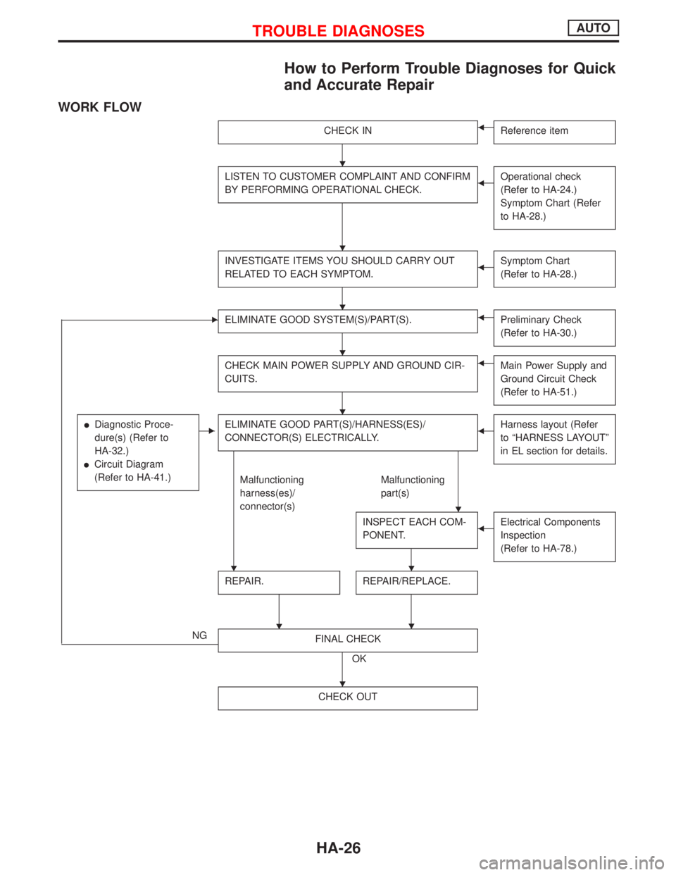
How to Perform Trouble Diagnoses for Quick
and Accurate Repair
WORK FLOW
CHECK INFReference item
LISTEN TO CUSTOMER COMPLAINT AND CONFIRM
BY PERFORMING OPERATIONAL CHECK.FOperational check
(Refer to HA-24.)
Symptom Chart (Refer
to HA-28.)
INVESTIGATE ITEMS YOU SHOULD CARRY OUT
RELATED TO EACH SYMPTOM.FSymptom Chart
(Refer to HA-28.)
EELIMINATE GOOD SYSTEM(S)/PART(S).FPreliminary Check
(Refer to HA-30.)
CHECK MAIN POWER SUPPLY AND GROUND CIR-
CUITS.FMain Power Supply and
Ground Circuit Check
(Refer to HA-51.)
lDiagnostic Proce-
dure(s) (Refer to
HA-32.)
lCircuit Diagram
(Refer to HA-41.)
EELIMINATE GOOD PART(S)/HARNESS(ES)/
CONNECTOR(S) ELECTRICALLY.FHarness layout (Refer
to ªHARNESS LAYOUTº
in EL section for details.
Malfunctioning
harness(es)/
connector(s)Malfunctioning
part(s)
INSPECT EACH COM-
PONENT.
FElectrical Components
Inspection
(Refer to HA-78.)
REPAIR.
H
REPAIR/REPLACE.
NGFINAL CHECK
OK
CHECK OUT
H
H
H
H
H
H
HH
H
H
TROUBLE DIAGNOSESAUTO
HA-26
Page 1889 of 2267
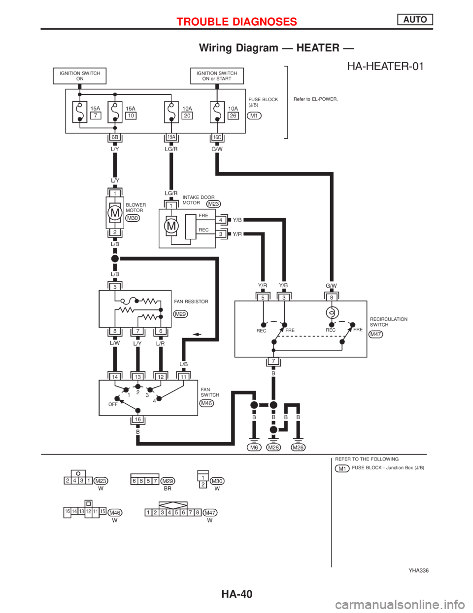
Wiring Diagram Ð HEATER Ð
YHA336
IGNITION SWITCH
ONIGNITION SWITCH
ON or START
FUSE BLOCK
(J/B)Refer to EL-POWER.
INTAKE DOOR
MOTOR
BLOWER
MOTOR
FAN RESISTOR
RECFRERECFRERECIRCULATION
SWITCH
FA N
SWITCH
OFF
REFER TO THE FOLLOWING
FUSE BLOCK - Junction Box (J/B) FRE
REC
TROUBLE DIAGNOSESAUTO
HA-40