1999 NISSAN PRIMERA fuel
[x] Cancel search: fuelPage 7 of 2267
Precautions for Supplemental Restraint System
(SRS) ªAIR BAGº and ªSEAT BELT
PRE-TENSIONERº
NCAT0002The Supplemental Restraint System ªAIR BAGº and ªSEAT BELT PRE-TENSIONERº, used along with a seat
belt, help to reduce the risk or severity of injury to the driver and front passenger in a frontal collision. The
Supplemental Restraint System consists of air bag modules (located in the center of the steering wheel and
on the instrument panel on the passenger side), seat belt pre-tensioners, a diagnosis sensor unit, warning
lamp, wiring harness and spiral cable.
In addition to the supplemental air bag modules for a frontal collision, the supplemental side air bag used along
with the seat belt helps to reduce the risk or severity of injury to the driver and front passenger in a side col-
lision. The supplemental side air bag consists of air bag modules (located in the outer side of front seats),
satellite sensor, diagnosis sensor unit (one of components of supplemental air bags for a frontal collision),
wiring harness, warning lamp (one of components of supplemental air bags for a frontal collision). Information
necessary to service the system safely is included in theRS sectionof this Service Manual.
WARNING:
ITo avoid rendering the SRS inoperative, which could increase the risk of personal injury or death
in the event of a collision which would result in air bag inflation, all maintenance must be performed
by an authorized NISSAN dealer.
IImproper maintenance, including incorrect removal and installation of the SRS, can lead to per-
sonal injury caused by unintentional activation of the system.
IDo not use electrical test equipment on any circuit related to the SRS unless instructed to in this
Service Manual. SRS wiring harnesses (except ªSEAT BELT PRE-TENSIONERº connector) can be
identified with yellow harness connector (and with yellow harness protector or yellow insulation
tape before the harness connectors).
Precautions for On Board Diagnostic (OBD)
System of CVT and Engine
NCAT0198The ECM has an on board diagnostic system. It will light up the malfunction indicator (MI) to warn the driver
of a malfunction causing emission deterioration.
CAUTION:
IBe sure to turn the ignition switch ªOFFº and disconnect the negative battery terminal before any
repair or inspection work. The open/short circuit of related switches, sensors, solenoid valves, etc.
will cause the MI to light up.
IBe sure to connect and lock the connectors securely after work. A loose (unlocked) connector will
cause the MI to light up due to an open circuit. (Be sure the connector is free from water, grease,
dirt, bent terminals, etc.)
IBe sure to route and secure the harnesses properly after work. Interference of the harness with a
bracket, etc. may cause the MI to light up due to a short circuit.
IBe sure to connect rubber tubes properly after work. A misconnected or disconnected rubber tube
may cause the MI to light up due to a malfunction of the EGR system or fuel injection system, etc.
IBe sure to erase the unnecessary malfunction information (repairs completed) from the TCM and
ECM before returning the vehicle to the customer.
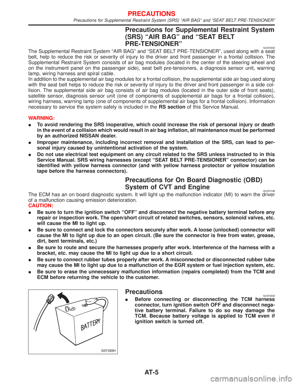
PrecautionsNCAT0003IBefore connecting or disconnecting the TCM harness
connector, turn ignition switch OFF and disconnect nega-
tive battery terminal. Failure to do so may damage the
TCM. Because battery voltage is applied to TCM even if
ignition switch is turned off.
SEF289H
PRECAUTIONS
Precautions for Supplemental Restraint System (SRS) ªAIR BAGº and ªSEAT BELT PRE-TENSIONERº
AT-5
Page 18 of 2267
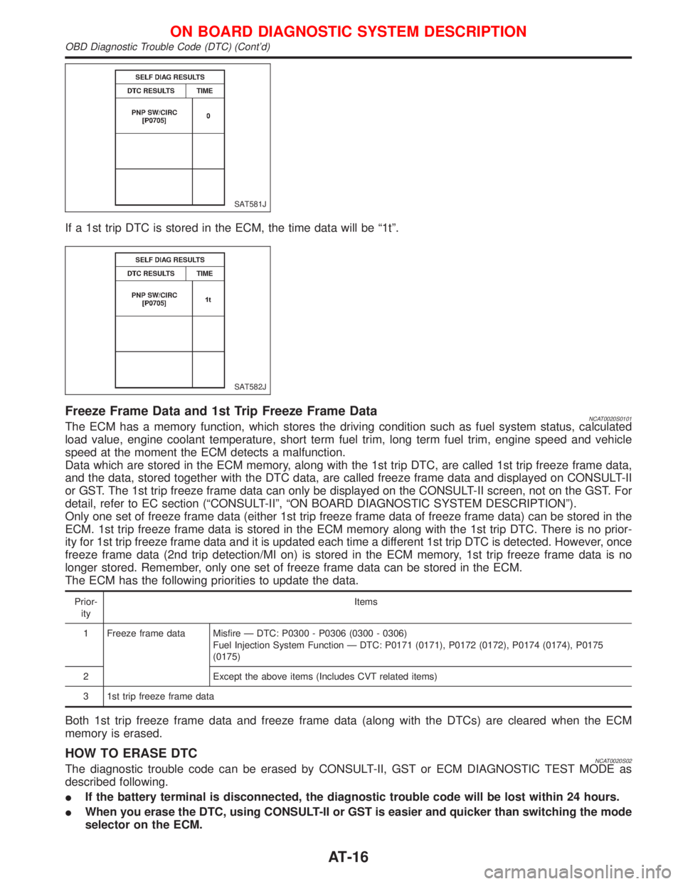
If a 1st trip DTC is stored in the ECM, the time data will be ª1tº.
Freeze Frame Data and 1st Trip Freeze Frame DataNCAT0020S0101The ECM has a memory function, which stores the driving condition such as fuel system status, calculated
load value, engine coolant temperature, short term fuel trim, long term fuel trim, engine speed and vehicle
speed at the moment the ECM detects a malfunction.
Data which are stored in the ECM memory, along with the 1st trip DTC, are called 1st trip freeze frame data,
and the data, stored together with the DTC data, are called freeze frame data and displayed on CONSULT-II
or GST. The 1st trip freeze frame data can only be displayed on the CONSULT-II screen, not on the GST. For
detail, refer to EC section (ªCONSULT-IIº, ªON BOARD DIAGNOSTIC SYSTEM DESCRIPTIONº).
Only one set of freeze frame data (either 1st trip freeze frame data of freeze frame data) can be stored in the
ECM. 1st trip freeze frame data is stored in the ECM memory along with the 1st trip DTC. There is no prior-
ity for 1st trip freeze frame data and it is updated each time a different 1st trip DTC is detected. However, once
freeze frame data (2nd trip detection/MI on) is stored in the ECM memory, 1st trip freeze frame data is no
longer stored. Remember, only one set of freeze frame data can be stored in the ECM.
The ECM has the following priorities to update the data.
Prior-
ityItems
1 Freeze frame data Misfire Ð DTC: P0300 - P0306 (0300 - 0306)
Fuel Injection System Function Ð DTC: P0171 (0171), P0172 (0172), P0174 (0174), P0175
(0175)
2 Except the above items (Includes CVT related items)
3 1st trip freeze frame data
Both 1st trip freeze frame data and freeze frame data (along with the DTCs) are cleared when the ECM
memory is erased.
HOW TO ERASE DTCNCAT0020S02The diagnostic trouble code can be erased by CONSULT-II, GST or ECM DIAGNOSTIC TEST MODE as
described following.
IIf the battery terminal is disconnected, the diagnostic trouble code will be lost within 24 hours.
IWhen you erase the DTC, using CONSULT-II or GST is easier and quicker than switching the mode
selector on the ECM.
SAT581J
SAT582J
ON BOARD DIAGNOSTIC SYSTEM DESCRIPTION
OBD Diagnostic Trouble Code (DTC) (Cont'd)
AT-16
Page 221 of 2267
Body Rear End and Opener
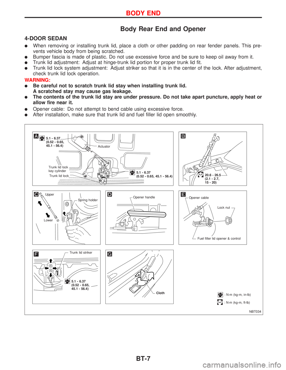
4-DOOR SEDAN
lWhen removing or installing trunk lid, place a cloth or other padding on rear fender panels. This pre-
vents vehicle body from being scratched.
lBumper fascia is made of plastic. Do not use excessive force and be sure to keep oil away from it.
lTrunk lid adjustment: Adjust at hinge-trunk lid portion for proper trunk lid fit.
lTrunk lid lock system adjustment: Adjust striker so that it is in the center of the lock. After adjustment,
check trunk lid lock operation.
WARNING:
lBe careful not to scratch trunk lid stay when installing trunk lid.
A scratched stay may cause gas leakage.
lThe contents of the trunk lid stay are under pressure. Do not take apart puncture, apply heat or
allow fire near it.
lOpener cable: Do not attempt to bend cable using excessive force.
lAfter installation, make sure that trunk lid and fuel filler lid open smoothly.
NBT034
5.1 - 6.37
(0.52 - 0.65,
45.1 - 56.4)
Upper
Spring holder
LowerOpener handle
Opener cable
Lock nut
Fuel filler lid opener & control
Trunk lid striker
.5.1 - 6.37
(0.52 - 0.65,
45.1 - 56.4)
: N´m (kg-m, ft-lb)
20.6 - 26.5
(2.1 - 2.7,
15 - 20)
: N´m (kg-m, in-lb) Cloth
Actuator
.Trunk lid lock
key cylinder
.Trunk lid lock
.5.1 - 6.37
(0.52 - 0.65, 45.1 - 56.4)
BODY END
BT-7
Page 223 of 2267
5-DOOR HATCHBACK
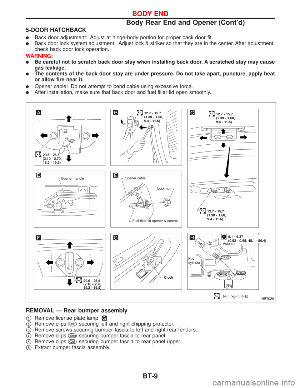
lBack door adjustment: Adjust at hinge-body portion for proper back door fit.
lBack door lock system adjustment: Adjust lock & striker so that they are in the center. After adjustment,
check back door lock operation.
WARNING:
lBe careful not to scratch back door stay when installing back door. A scratched stay may cause
gas leakage.
lThe contents of the back door stay are under pressure. Do not take apart, puncture, apply heat
or allow fire near it.
lOpener cable: Do not attempt to bend cable using excessive force.
lAfter installation, make sure that back door and fuel filler lid open smoothly.
REMOVAL Ð Rear bumper assembly
p1Remove license plate lamp
p2Remove clipsC203securing left and right chipping protector.
p3Remove screws securing bumper fascia to left and right rear fenders.
p4Remove clipsCS101securing bumper fascia to rear panel.
p5Remove clipsC205securing bumper fascia to rear panel upper.
p6Extract bumper fascia assembly.
NBT036 Opener handleOpener cable
Lock nut
Fuel filler lid opener & control
20.6 - 26.5
(2.10 - 2.70,
15.2 - 19.5)
12.7 - 15.7
(1.30 - 1.60,
9.4 - 11.6)12.7 - 15.7
(1.30 - 1.60,
9.4 - 11.6)
12.7 - 15.7
(1.30 - 1.60,
9.4 - 11.6)
20.6 - 26.5
(2.10 - 2.70,
15.2 - 19.5)
: N´m (kg-m, ft-lb) Cloth
.5.1 - 6.37
(0.52 - 0.65, 45.1 - 56.4)
Actuator
Key
cylinder
BODY END
Body Rear End and Opener (Cont'd)
BT-9
Page 225 of 2267
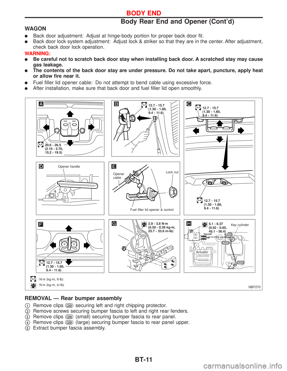
WAGON
lBack door adjustment: Adjust at hinge-body portion for proper back door fit.
lBack door lock system adjustment: Adjust lock & striker so that they are in the center. After adjustment,
check back door lock operation.
WARNING:
lBe careful not to scratch back door stay when installing back door. A scratched stay may cause
gas leakage.
lThe contents of the back door stay are under pressure. Do not take apart, puncture, apply heat
or allow fire near it.
lFuel filler lid opener cable: Do not attempt to bend cable using excessive force.
lAfter installation, make sure that back door and fuel filler lid open smoothly.
REMOVAL Ð Rear bumper assembly
p1Remove clipsC203securing left and right chipping protector.
p2Remove screws securing bumper fascia to left and right rear fenders.
p3Remove clipsC205(small) securing bumper fascia to rear panel.
p4Remove clipsC205(large) securing bumper fascia to rear panel upper.
p5Extract bumper fascia assembly.
NBF270 Opener handle
Opener
cableLock nut
.Fuel filler lid opener & control
.20.6 - 26.5
(2.10 - 2.70,
15.2 - 19.5)
12.7 - 15.7
(1.30 - 1.60,
9.4 - 11.6)12.7 - 15.7
(1.30 - 1.60,
9.4 - 11.6)
12.7 - 15.7
(1.30 - 1.60,
9.4 - 11.6)
.12.7 - 15.7
(1.30 - 1.60,
9.4 - 11.6)
: N´m (kg-m, ft-lb)
: N´m (kg-m, in-lb)
2.9 - 3.8 N´m
(0.30 - 0.39 kg-m,
25.7 - 33.6 in-lb)..5.1 - 6.37
(0.52 - 0.65,
45.1 - 56.4)Key cylinder
Actuator
BODY END
Body Rear End and Opener (Cont'd)
BT-11
Page 226 of 2267
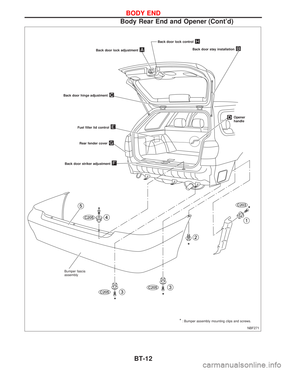
NBF271 Back door lock adjustment
Back door hinge adjustment
Back door stay installation
Opener
handle
Fuel filler lid control
Back door striker adjustment
*: Bumper assembly mounting clips and screws. Bumper fascia
assemblyRear fender cover
Back door lock control
BODY END
Body Rear End and Opener (Cont'd)
BT-12
Page 295 of 2267
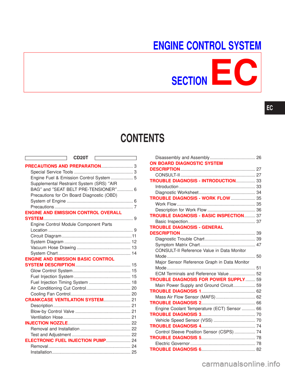
ENGINE CONTROL SYSTEM
SECTION
EC
CONTENTS
CD20T
PRECAUTIONS AND PREPARATION.......................... 3
Special Service Tools ................................................ 3
Engine Fuel & Emission Control System .................. 5
Supplemental Restraint System (SRS)²AIR
BAG²and²SEAT BELT PRE-TENSIONER²............. 6
Precautions for On Board Diagnostic (OBD)
System of Engine ...................................................... 6
Precautions ................................................................ 7
ENGINE AND EMISSION CONTROL OVERALL
SYSTEM......................................................................... 9
Engine Control Module Component Parts
Location ..................................................................... 9
Circuit Diagram ......................................................... 11
System Diagram ...................................................... 12
Vacuum Hose Drawing ............................................ 13
System Chart ........................................................... 14
ENGINE AND EMISSION BASIC CONTROL
SYSTEM DESCRIPTION............................................. 15
Glow Control System ............................................... 15
Fuel Injection System .............................................. 15
Fuel Injection Timing System .................................. 18
Air Conditioning Cut Control .................................... 20
Cooling Fan Control................................................. 20
CRANKCASE VENTILATION SYSTEM...................... 21
Description ............................................................... 21
Blow-by Control Valve ............................................. 21
Ventilation Hose ....................................................... 21
INJECTION NOZZLE................................................... 22
Removal and Installation ......................................... 22
Test and Adjustment ................................................ 22
ELECTRONIC FUEL INJECTION PUMP.................... 24
Removal ................................................................... 24
Installation ................................................................ 25Disassembly and Assembly ..................................... 26
ON BOARD DIAGNOSTIC SYSTEM
DESCRIPTION............................................................. 27
CONSULT-II ............................................................. 27
TROUBLE DIAGNOSIS - INTRODUCTION................ 33
Introduction .............................................................. 33
Diagnostic Worksheet .............................................. 34
TROUBLE DIAGNOSIS - WORK FLOW.................... 35
Work Flow ................................................................ 35
Description for Work Flow ....................................... 36
TROUBLE DIAGNOSIS - BASIC INSPECTION......... 37
Basic Inspection....................................................... 37
TROUBLE DIAGNOSIS - GENERAL
DESCRIPTION............................................................. 39
Diagnostic Trouble Chart ......................................... 39
Symptom Matrix Chart ............................................. 47
CONSULT-II Reference Value in Data Monitor
Mode ........................................................................ 50
Major Sensor Reference Graph in Data Monitor
Mode ........................................................................ 51
ECM Terminals and Reference Value ..................... 52
TROUBLE DIAGNOSIS FOR POWER SUPPLY........ 59
Main Power Supply and Ground Circuit .................. 59
TROUBLE DIAGNOSIS 1............................................ 62
Mass Air Flow Sensor (MAFS) ................................ 62
TROUBLE DIAGNOSIS 2............................................ 66
Engine Coolant Temperature (ECT) Sensor ........... 66
TROUBLE DIAGNOSIS 3............................................ 70
Vehicle Speed Sensor (VSS) .................................. 70
TROUBLE DIAGNOSIS 4............................................ 74
Control Sleeve Position Sensor (CSPS) ................. 74
TROUBLE DIAGNOSIS 5............................................ 78
Electric Governor ..................................................... 78
TROUBLE DIAGNOSIS 6............................................ 82
EC
Page 296 of 2267
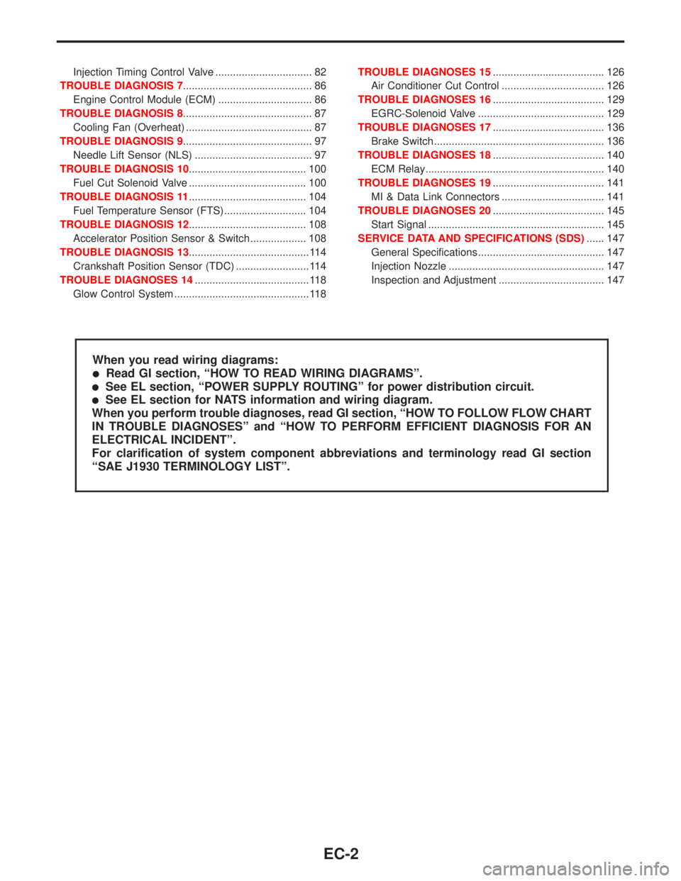
Injection Timing Control Valve ................................. 82
TROUBLE DIAGNOSIS 7............................................ 86
Engine Control Module (ECM) ................................ 86
TROUBLE DIAGNOSIS 8............................................ 87
Cooling Fan (Overheat) ........................................... 87
TROUBLE DIAGNOSIS 9............................................ 97
Needle Lift Sensor (NLS) ........................................ 97
TROUBLE DIAGNOSIS 10........................................ 100
Fuel Cut Solenoid Valve ........................................ 100
TROUBLE DIAGNOSIS 11........................................ 104
Fuel Temperature Sensor (FTS)............................ 104
TROUBLE DIAGNOSIS 12........................................ 108
Accelerator Position Sensor & Switch ................... 108
TROUBLE DIAGNOSIS 13......................................... 114
Crankshaft Position Sensor (TDC) ......................... 114
TROUBLE DIAGNOSES 14....................................... 118
Glow Control System .............................................. 118TROUBLE DIAGNOSES 15...................................... 126
Air Conditioner Cut Control ................................... 126
TROUBLE DIAGNOSES 16...................................... 129
EGRC-Solenoid Valve ........................................... 129
TROUBLE DIAGNOSES 17...................................... 136
Brake Switch .......................................................... 136
TROUBLE DIAGNOSES 18...................................... 140
ECM Relay............................................................. 140
TROUBLE DIAGNOSES 19...................................... 141
MI & Data Link Connectors ................................... 141
TROUBLE DIAGNOSES 20...................................... 145
Start Signal ............................................................ 145
SERVICE DATA AND SPECIFICATIONS (SDS)...... 147
General Specifications ........................................... 147
Injection Nozzle ..................................................... 147
Inspection and Adjustment .................................... 147
When you read wiring diagrams:
lRead GI section, ªHOW TO READ WIRING DIAGRAMSº.
lSee EL section, ªPOWER SUPPLY ROUTINGº for power distribution circuit.
lSee EL section for NATS information and wiring diagram.
When you perform trouble diagnoses, read GI section, ªHOW TO FOLLOW FLOW CHART
IN TROUBLE DIAGNOSESº and ªHOW TO PERFORM EFFICIENT DIAGNOSIS FOR AN
ELECTRICAL INCIDENTº.
For clarification of system component abbreviations and terminology read GI section
ªSAE J1930 TERMINOLOGY LISTº.
EC-2