1999 NISSAN PRIMERA brake pads
[x] Cancel search: brake padsPage 125 of 2267
Supplemental Restraint System (SRS) ªAIR
BAGº and ªSEAT BELT PRE-TENSIONERº
The Supplemental Restraint System such as ªAIR BAGº and ªSEAT BELT PRE-TENSIONERº used along
with a seat belt, helps to reduce the risk or severity of injury to the driver and front passenger for certain
types of collision. The SRS system composition which is available to NISSAN MODEL P11 is as follows (The
composition varies according to the destination and optional equipment.):
lFor a frontal collision
The Supplemental Restraint System consists of driver air bag module (located in the center of the
steering wheel), front passenger air bag module (located on the instrument panel on passenger side),
front seat belt pre-tensioners, a diagnosis sensor unit, warning lamp, wiring harness and spiral cable.
lFor a side collision
The Supplemental Restraint System consists of front side air bag module (located in the outer side of
front seat), side air bag (satellite) sensor, diagnosis sensor unit (one of components of air bags for a
frontal collision), wiring harness, warning lamp (one of components of air bags for a frontal collision).
Information necessary to service the system safely is included in theRS sectionof this Service Manual.
WARNING:
lTo avoid rendering the SRS inoperative, which could increase the risk of personal injury or death
in the event of a collision which would result in air bag inflation, all maintenance should be per-
formed by an authorized NISSAN dealer.
lImproper maintenance, including incorrect removal and installation of the SRS, can lead to per-
sonal injury caused by unintentional activation of the system. For removal of Spiral Cable and
Air Bag Module, see the RS section.
lDo not use electrical test equipment on any circuit related to the SRS unless instructed to in this
Service Manual. Spiral cable and wiring harnesses covered with yellow insulation tape either just
before the harness connectors or for the complete harness are related to the SRS.
Precautions for Brake System
lRecommended fluid is brake fluid ªDOT 4º.
lNever reuse drained brake fluid.
lBe careful not to splash brake fluid on painted areas.
lTo clean or wash all parts of master cylinder, disc brake
caliper and wheel cylinder, use clean brake fluid.
lNever use mineral oils such as gasoline or kerosene.
They will ruin rubber parts of the hydraulic system.
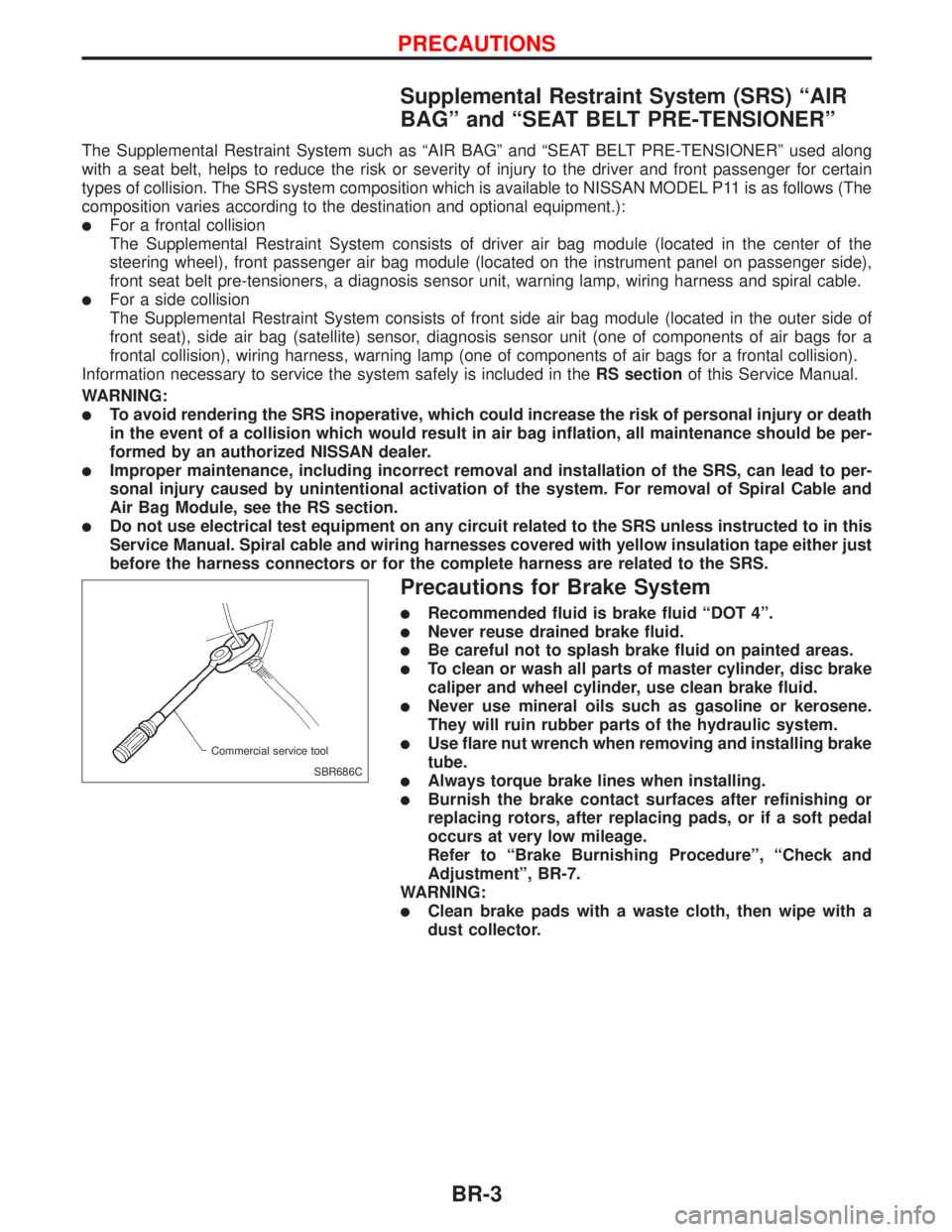
lUse flare nut wrench when removing and installing brake
tube.
lAlways torque brake lines when installing.
lBurnish the brake contact surfaces after refinishing or
replacing rotors, after replacing pads, or if a soft pedal
occurs at very low mileage.
Refer to ªBrake Burnishing Procedureº, ªCheck and
Adjustmentº, BR-7.
WARNING:
lClean brake pads with a waste cloth, then wipe with a
dust collector.
SBR686C Commercial service tool
PRECAUTIONS
BR-3
Page 126 of 2267
Precautions When Working On ABS
lUse recommended tyres in combination with ABS.
lInstall tyres or studded tyres, etc. with the same size.
lIf different sizes of tyres, or tyres other than the ones
recommended for use with the ABS, are fitted, stopping
distance will increase and control and stability could
deteriorate.
lWhen changing brake pads, use Nissan genuine parts.
lWhen fitting radios etc, do not position the radio unit,
antenna, or antenna cables within an area of about 100
mm (3.94 in) of the control unit.
lWhen doing any work that requires electro-welding, first
remove the control unit.
lMake sure when taking a power supply for the audio,
lamps etc., not to take this from any ABS-related har-
ness. (Refer to the electrical wiring diagrams for ABS-
related harnesses)
Wiring Diagrams and Trouble Diagnosis
When you read wiring diagrams, refer to the following:
lGI-11, ªHOW TO READ WIRING DIAGRAMSº
lEL-10, ªPOWER SUPPLY ROUTINGº
When you perform trouble diagnosis, refer to the following:
lGI-35, ªHOW TO FOLLOW TEST GROUPS IN TROUBLE DIAGNOSISº
lGI-24, ªHOW TO PERFORM EFFICIENT DIAGNOSES FOR AN ELECTRICAL INCIDENTº
PRECAUTIONS
BR-4
Page 128 of 2267
NVH Troubleshooting Chart
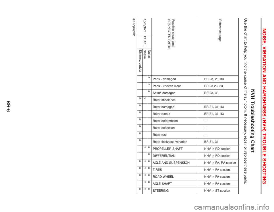
Use the chart to help you find the cause of the symptom. If necessary, repair or replace these parts.
Reference page
BR-23, 26, 33
BR-23 26, 33
BR-23, 33
Ð
BR-31, 37, 43
BR-31, 37, 43
Ð
Ð
Ð
BR-31, 37
NHV in PD section
NHV in PD section
NHV in FA, RA section
NHV in FA section
NHV in FA section
NHV in FA section
NHV in ST section
Possible cause and
SUSPECTED PARTS
Pads - damaged
Pads - uneven wear
Shims damaged
Rotor imbalance
Rotor damaged
Rotor runout
Rotor deformation
Rotor deflection
Rotor rust
Rotor thickness variation
PROPELLER SHAFT
DIFFERENTIAL
AXLE AND SUSPENSION
TIRES
ROAD WHEEL
AXLE SHAFT
STEERING
Symptom BRAKENoise x x xxxxxxxx
Shake x xxxxxx
Shimmy, Judderxxxxxxx xxx x
X : Applicable
NOISE, VIBRATION AND HARSHNESS (NVH) TROUBLE SHOOTING
BR-6
Page 129 of 2267
Checking Brake Fluid Level
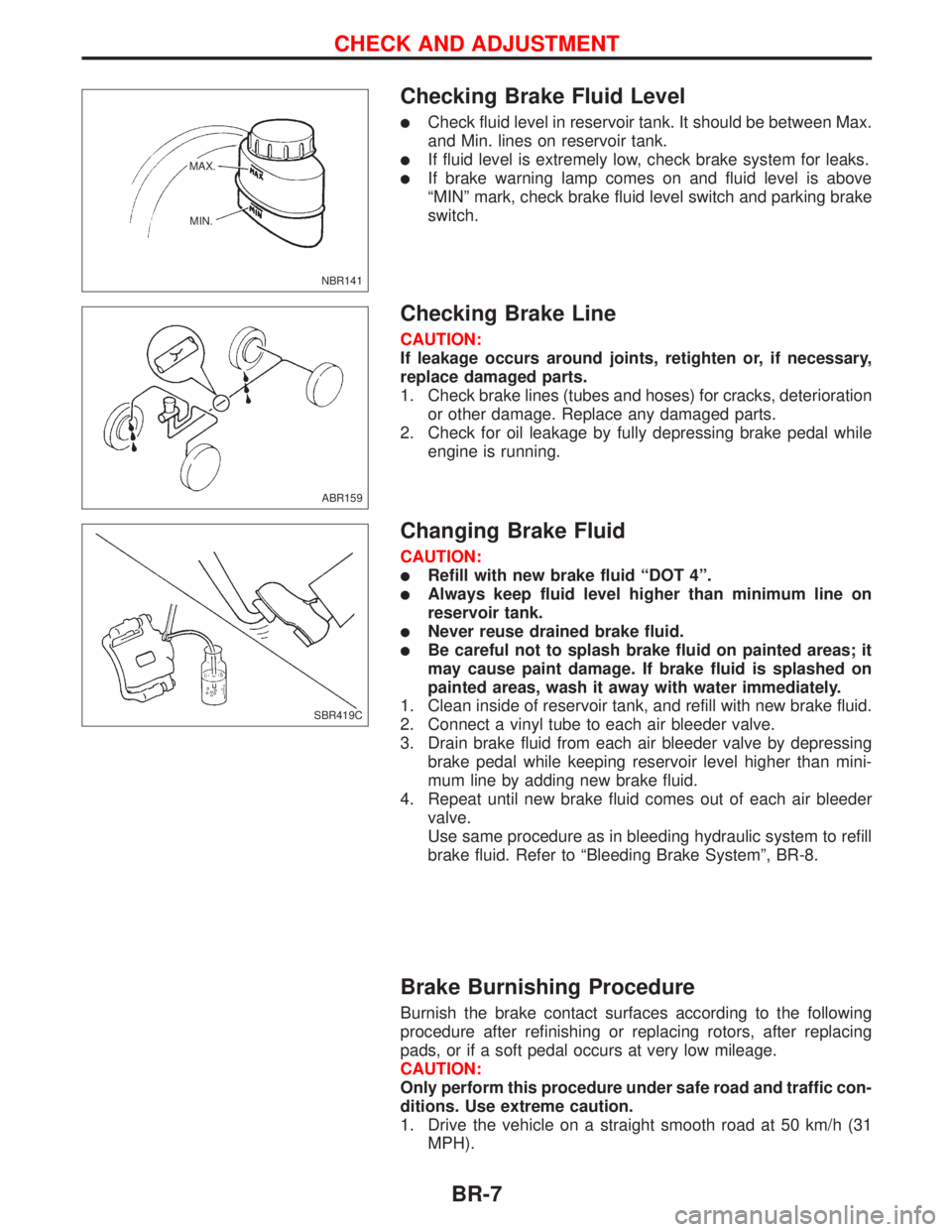
lCheck fluid level in reservoir tank. It should be between Max.
and Min. lines on reservoir tank.
lIf fluid level is extremely low, check brake system for leaks.
lIf brake warning lamp comes on and fluid level is above
ªMINº mark, check brake fluid level switch and parking brake
switch.
Checking Brake Line
CAUTION:
If leakage occurs around joints, retighten or, if necessary,
replace damaged parts.
1. Check brake lines (tubes and hoses) for cracks, deterioration
or other damage. Replace any damaged parts.
2. Check for oil leakage by fully depressing brake pedal while
engine is running.
Changing Brake Fluid
CAUTION:
lRefill with new brake fluid ªDOT 4º.
lAlways keep fluid level higher than minimum line on
reservoir tank.
lNever reuse drained brake fluid.
lBe careful not to splash brake fluid on painted areas; it
may cause paint damage. If brake fluid is splashed on
painted areas, wash it away with water immediately.
1. Clean inside of reservoir tank, and refill with new brake fluid.
2. Connect a vinyl tube to each air bleeder valve.
3. Drain brake fluid from each air bleeder valve by depressing
brake pedal while keeping reservoir level higher than mini-
mum line by adding new brake fluid.
4. Repeat until new brake fluid comes out of each air bleeder
valve.
Use same procedure as in bleeding hydraulic system to refill
brake fluid. Refer to ªBleeding Brake Systemº, BR-8.
Brake Burnishing Procedure
Burnish the brake contact surfaces according to the following
procedure after refinishing or replacing rotors, after replacing
pads, or if a soft pedal occurs at very low mileage.
CAUTION:
Only perform this procedure under safe road and traffic con-
ditions. Use extreme caution.
1. Drive the vehicle on a straight smooth road at 50 km/h (31
MPH).
NBR141 MAX.
MIN.
ABR159
SBR419C
CHECK AND ADJUSTMENT
BR-7
Page 145 of 2267
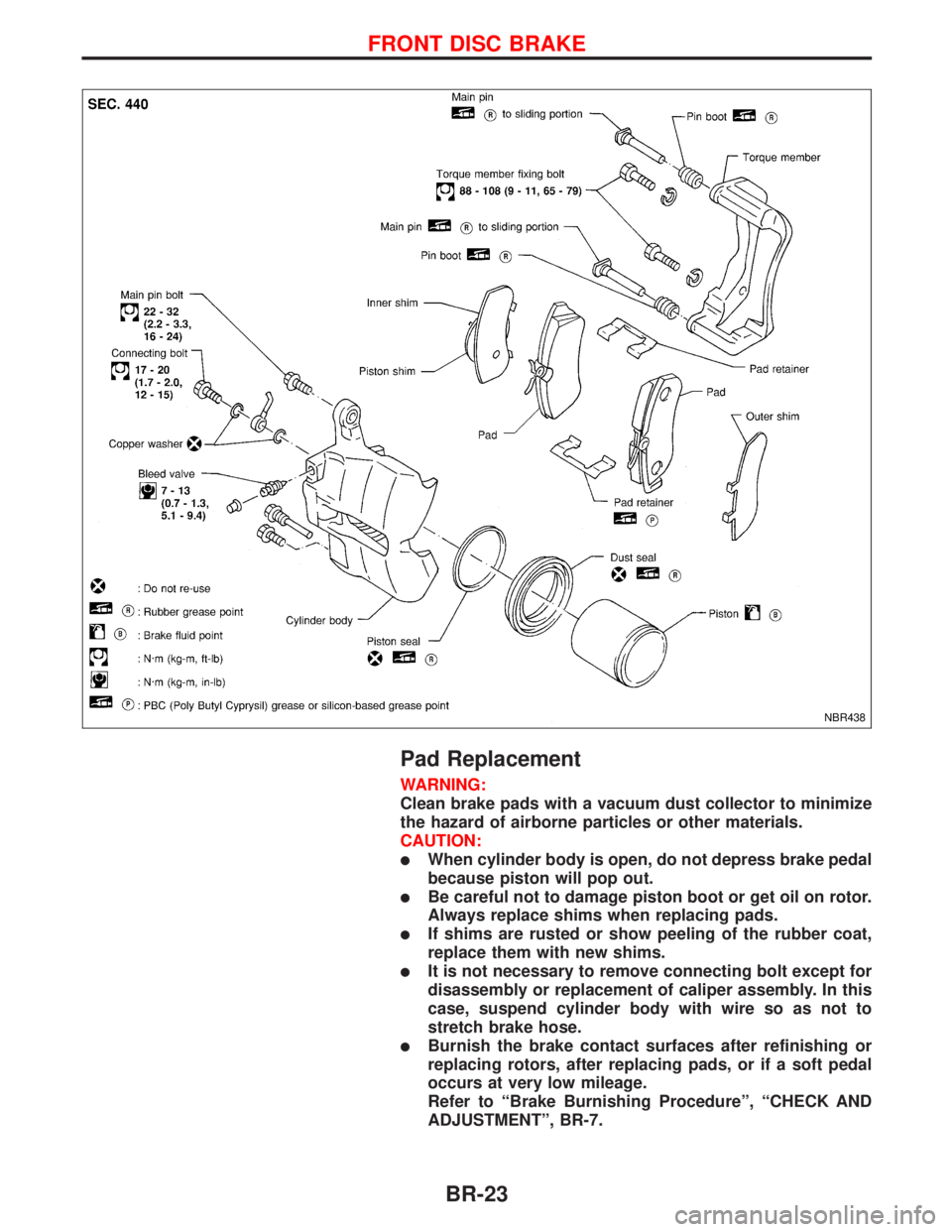
Pad Replacement
WARNING:
Clean brake pads with a vacuum dust collector to minimize
the hazard of airborne particles or other materials.
CAUTION:
lWhen cylinder body is open, do not depress brake pedal
because piston will pop out.
lBe careful not to damage piston boot or get oil on rotor.
Always replace shims when replacing pads.
lIf shims are rusted or show peeling of the rubber coat,
replace them with new shims.
lIt is not necessary to remove connecting bolt except for
disassembly or replacement of caliper assembly. In this
case, suspend cylinder body with wire so as not to
stretch brake hose.
lBurnish the brake contact surfaces after refinishing or
replacing rotors, after replacing pads, or if a soft pedal
occurs at very low mileage.
Refer to ªBrake Burnishing Procedureº, ªCHECK AND
ADJUSTMENTº, BR-7.
NBR438
FRONT DISC BRAKE
BR-23
Page 146 of 2267
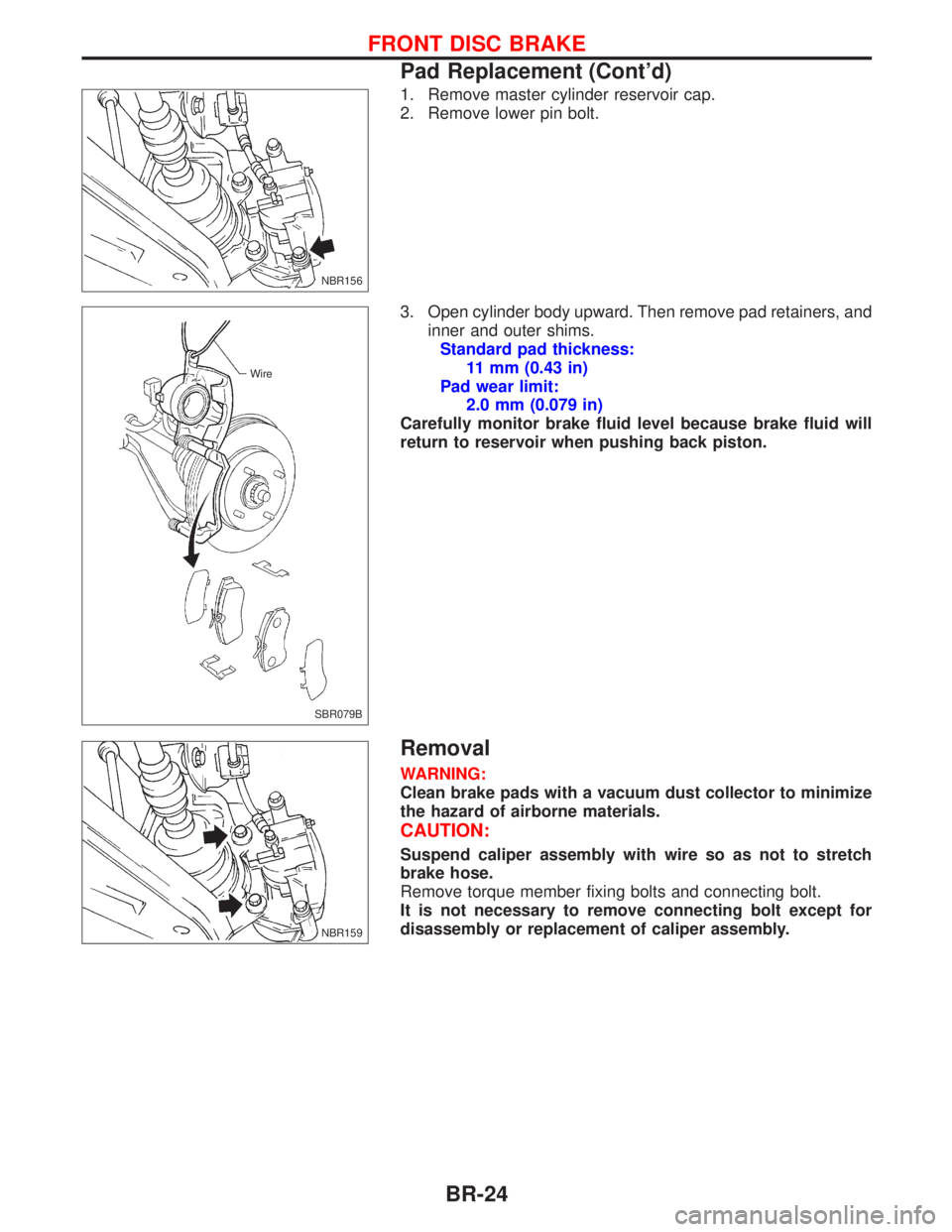
1. Remove master cylinder reservoir cap.
2. Remove lower pin bolt.
3. Open cylinder body upward. Then remove pad retainers, and
inner and outer shims.
Standard pad thickness:
11 mm (0.43 in)
Pad wear limit:
2.0 mm (0.079 in)
Carefully monitor brake fluid level because brake fluid will
return to reservoir when pushing back piston.
Removal
WARNING:
Clean brake pads with a vacuum dust collector to minimize
the hazard of airborne materials.
CAUTION:
Suspend caliper assembly with wire so as not to stretch
brake hose.
Remove torque member fixing bolts and connecting bolt.
It is not necessary to remove connecting bolt except for
disassembly or replacement of caliper assembly.
NBR156
SBR079B Wire
NBR159
FRONT DISC BRAKE
Pad Replacement (Cont'd)
BR-24
Page 148 of 2267
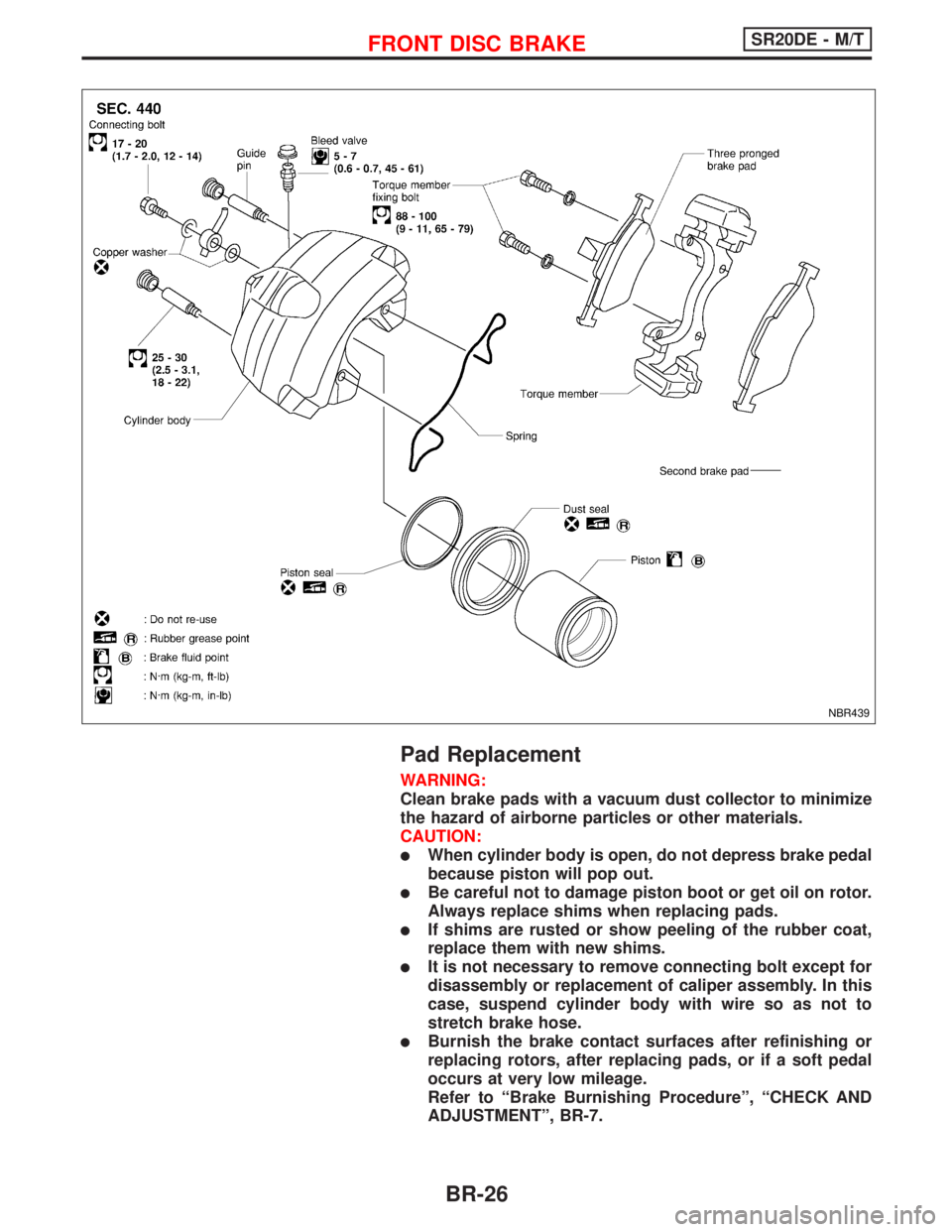
Pad Replacement
WARNING:
Clean brake pads with a vacuum dust collector to minimize
the hazard of airborne particles or other materials.
CAUTION:
lWhen cylinder body is open, do not depress brake pedal
because piston will pop out.
lBe careful not to damage piston boot or get oil on rotor.
Always replace shims when replacing pads.
lIf shims are rusted or show peeling of the rubber coat,
replace them with new shims.
lIt is not necessary to remove connecting bolt except for
disassembly or replacement of caliper assembly. In this
case, suspend cylinder body with wire so as not to
stretch brake hose.
lBurnish the brake contact surfaces after refinishing or
replacing rotors, after replacing pads, or if a soft pedal
occurs at very low mileage.
Refer to ªBrake Burnishing Procedureº, ªCHECK AND
ADJUSTMENTº, BR-7.
NBR439
FRONT DISC BRAKESR20DE - M/T
BR-26
Page 151 of 2267
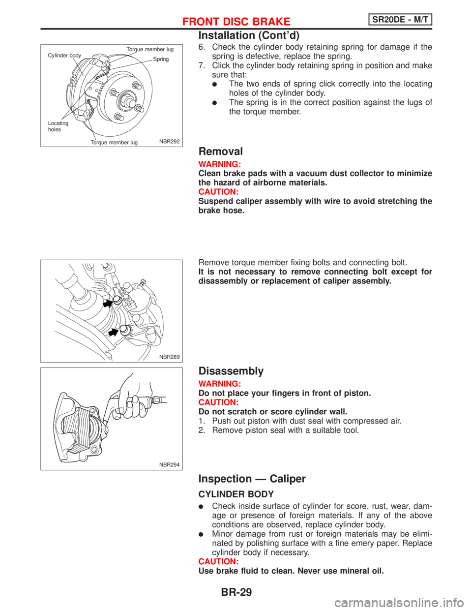
6. Check the cylinder body retaining spring for damage if the
spring is defective, replace the spring.
7. Click the cylinder body retaining spring in position and make
sure that:
lThe two ends of spring click correctly into the locating
holes of the cylinder body.
lThe spring is in the correct position against the lugs of
the torque member.
Removal
WARNING:
Clean brake pads with a vacuum dust collector to minimize
the hazard of airborne materials.
CAUTION:
Suspend caliper assembly with wire to avoid stretching the
brake hose.
Remove torque member fixing bolts and connecting bolt.
It is not necessary to remove connecting bolt except for
disassembly or replacement of caliper assembly.
Disassembly
WARNING:
Do not place your fingers in front of piston.
CAUTION:
Do not scratch or score cylinder wall.
1. Push out piston with dust seal with compressed air.
2. Remove piston seal with a suitable tool.
Inspection Ð Caliper
CYLINDER BODY
lCheck inside surface of cylinder for score, rust, wear, dam-
age or presence of foreign materials. If any of the above
conditions are observed, replace cylinder body.
lMinor damage from rust or foreign materials may be elimi-
nated by polishing surface with a fine emery paper. Replace
cylinder body if necessary.
CAUTION:
Use brake fluid to clean. Never use mineral oil.
NBR292 Spring Cylinder bodyTorque member lug
Torque member lug Locating
holes
NBR289
NBR294
FRONT DISC BRAKESR20DE - M/T
Installation (Cont'd)
BR-29