Page 1468 of 2267
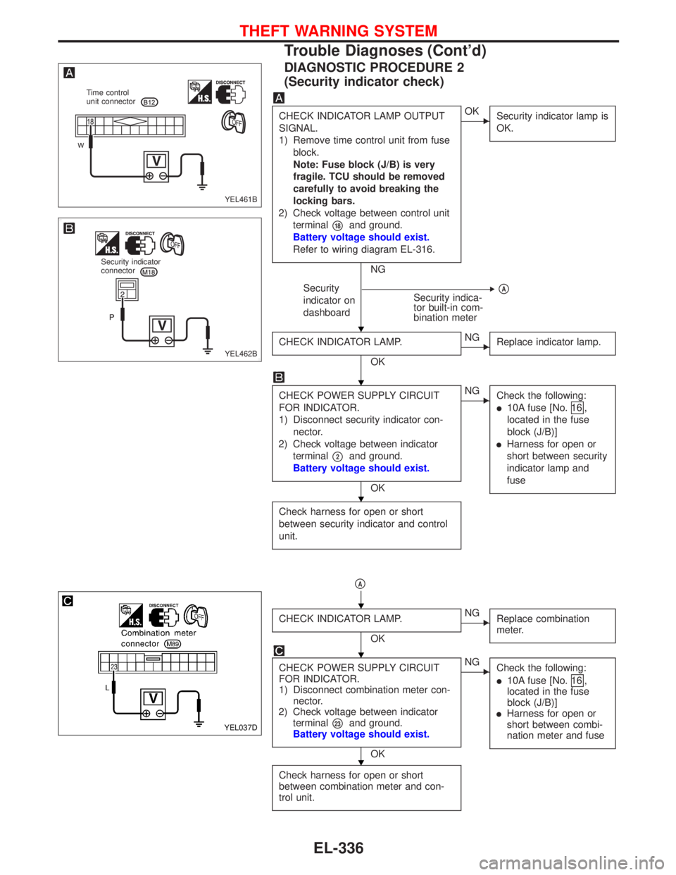
DIAGNOSTIC PROCEDURE 2
(Security indicator check)
CHECK INDICATOR LAMP OUTPUT
SIGNAL.
1) Remove time control unit from fuse
block.
Note: Fuse block (J/B) is very
fragile. TCU should be removed
carefully to avoid breaking the
locking bars.
2) Check voltage between control unit
terminal
�18and ground.
Battery voltage should exist.
Refer to wiring diagram EL-316.
NG
�OK
Security indicator lamp is
OK.
Security
indicator on
dashboardSecurity indica-
tor built-in com-
bination meter��A
CHECK INDICATOR LAMP.
OK
�NG
Replace indicator lamp.
CHECK POWER SUPPLY CIRCUIT
FOR INDICATOR.
1) Disconnect security indicator con-
nector.
2) Check voltage between indicator
terminal
�2and ground.
Battery voltage should exist.
OK
�NG
Check the following:
�10A fuse [No.16 ,
located in the fuse
block (J/B)]
�Harness for open or
short between security
indicator lamp and
fuse
Check harness for open or short
between security indicator and control
unit.
�A
CHECK INDICATOR LAMP.
OK
�NG
Replace combination
meter.
CHECK POWER SUPPLY CIRCUIT
FOR INDICATOR.
1) Disconnect combination meter con-
nector.
2) Check voltage between indicator
terminal
�23and ground.
Battery voltage should exist.
OK
�NG
Check the following:
�10A fuse [No.16 ,
located in the fuse
block (J/B)]
�Harness for open or
short between combi-
nation meter and fuse
Check harness for open or short
between combination meter and con-
trol unit.
YEL461B Time control
unit connector
YEL462B Security indicator
connector
YEL037D
�
�
�
�
�
�
THEFT WARNING SYSTEM
Trouble Diagnoses (Cont’d)
EL-336
Page 1469 of 2267
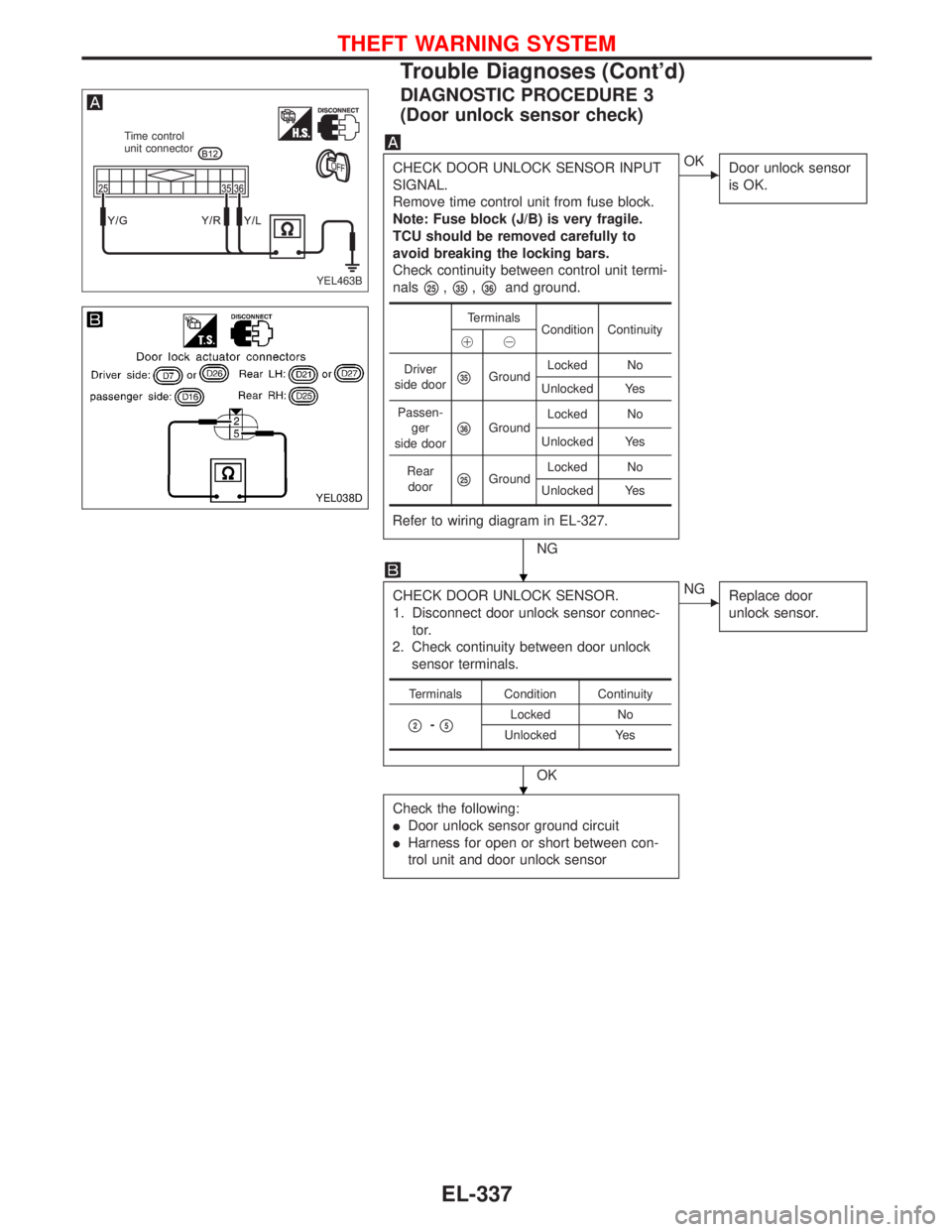
DIAGNOSTIC PROCEDURE 3
(Door unlock sensor check)
CHECK DOOR UNLOCK SENSOR INPUT
SIGNAL.
Remove time control unit from fuse block.
Note: Fuse block (J/B) is very fragile.
TCU should be removed carefully to
avoid breaking the locking bars.
Check continuity between control unit termi-
nals
�25,�35,�36and ground.
Refer to wiring diagram in EL-327.
NG
�OK
Door unlock sensor
is OK.
CHECK DOOR UNLOCK SENSOR.
1. Disconnect door unlock sensor connec-
tor.
2. Check continuity between door unlock
sensor terminals.
OK
�NG
Replace door
unlock sensor.
Check the following:
�Door unlock sensor ground circuit
�Harness for open or short between con-
trol unit and door unlock sensor
Terminals
Condition Continuity
��
Driver
side door
�35GroundLocked No
Unlocked Yes
Passen-
ger
side door
�36GroundLocked No
Unlocked Yes
Rear
door
�25GroundLocked No
Unlocked Yes
Terminals Condition Continuity
�2-�5Locked No
Unlocked Yes
YEL463B
Time control
unit connector
YEL038D
�
�
THEFT WARNING SYSTEM
Trouble Diagnoses (Cont’d)
EL-337
Page 1472 of 2267
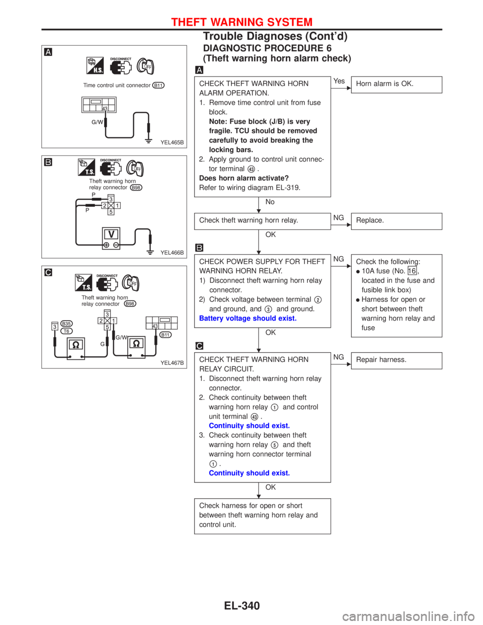
DIAGNOSTIC PROCEDURE 6
(Theft warning horn alarm check)
CHECK THEFT WARNING HORN
ALARM OPERATION.
1. Remove time control unit from fuse
block.
Note: Fuse block (J/B) is very
fragile. TCU should be removed
carefully to avoid breaking the
locking bars.
2. Apply ground to control unit connec-
tor terminal
�43.
Does horn alarm activate?
Refer to wiring diagram EL-319.
No
�Ye s
Horn alarm is OK.
Check theft warning horn relay.
OK
�NG
Replace.
CHECK POWER SUPPLY FOR THEFT
WARNING HORN RELAY.
1) Disconnect theft warning horn relay
connector.
2) Check voltage between terminal
�2
and ground, and�3and ground.
Battery voltage should exist.
OK
�NG
Check the following:
�10A fuse (No.16 ,
located in the fuse and
fusible link box)
�Harness for open or
short between theft
warning horn relay and
fuse
CHECK THEFT WARNING HORN
RELAY CIRCUIT.
1. Disconnect theft warning horn relay
connector.
2. Check continuity between theft
warning horn relay
�1and control
unit terminal
�43.
Continuity should exist.
3. Check continuity between theft
warning horn relay
�5and theft
warning horn connector terminal
�1.
Continuity should exist.
OK
�NG
Repair harness.
Check harness for open or short
between theft warning horn relay and
control unit.
YEL465B
Time control unit connector
YEL466B
Theft warning horn
relay connector
YEL467B
Theft warning horn
relay connector
�
�
�
�
THEFT WARNING SYSTEM
Trouble Diagnoses (Cont’d)
EL-340
Page 1475 of 2267
Wiring Diagram—NATS—
MODELS BEFORE VIN - P11U0548750 (Type-1)
YEL216C
BATTERY BATTERYIGNITION SWITCH
ON or START
FUSE
BLOCK
(J/B)Refer to EL-POWER.
NATS
SECURITY
INDICATORAUDIODONGLE
CONTROL UNIT: With gasoline engine
: With diesel engine
: With GA engine
: With SR engine or
QG engine
: RHD models
: Except
INJECTION
PUMPTIME
CONTROL
UNIT
REFER TO THE FOLLOWING
FUSE BLOCK - Junction Box (J/B)
FUSE BLOCK - Junction Box (J/B)
FUSE BLOCK - Junction Box (J/B)
FUSE BLOCK - Junction Box (J/B)
FUSE BLOCK - Junction Box (J/B)
NATS (Nissan Anti-Theft System)
EL-343
Page 1476 of 2267
MODELS AFTER VIN - P11U0548750 (Type-2)
YEL936C
NATS (Nissan Anti-Theft System)
Wiring Diagram—NATS—(Cont’d)
EL-344
Page 1483 of 2267
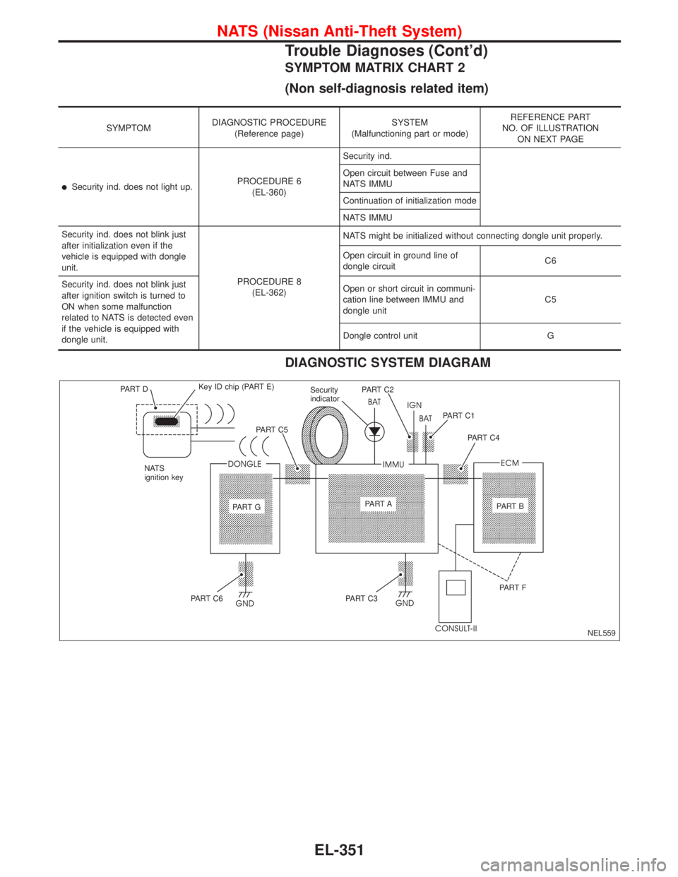
SYMPTOM MATRIX CHART 2
(Non self-diagnosis related item)
SYMPTOMDIAGNOSTIC PROCEDURE
(Reference page)SYSTEM
(Malfunctioning part or mode)REFERENCE PART
NO. OF ILLUSTRATION
ON NEXT PAGE
�Security ind. does not light up.PROCEDURE 6
(EL-360)Security ind.
Open circuit between Fuse and
NATS IMMU
Continuation of initialization mode
NATS IMMU
Security ind. does not blink just
after initialization even if the
vehicle is equipped with dongle
unit.
PROCEDURE 8
(EL-362)NATS might be initialized without connecting dongle unit properly.
Open circuit in ground line of
dongle circuitC6
Security ind. does not blink just
after ignition switch is turned to
ON when some malfunction
related to NATS is detected even
if the vehicle is equipped with
dongle unit.Open or short circuit in communi-
cation line between IMMU and
dongle unitC5
Dongle control unit G
DIAGNOSTIC SYSTEM DIAGRAM
NEL559 PA R T DKey ID chip (PART E)
NATS
ignition keyPA R T C 5Security
indicatorPA R T C 2
PA R T C 1
PA R T C 4
PA R T GPA R T A
PA R T B
PA R T C 6PA R T C 3PA R T F
NATS (Nissan Anti-Theft System)
Trouble Diagnoses (Cont’d)
EL-351
Page 1796 of 2267
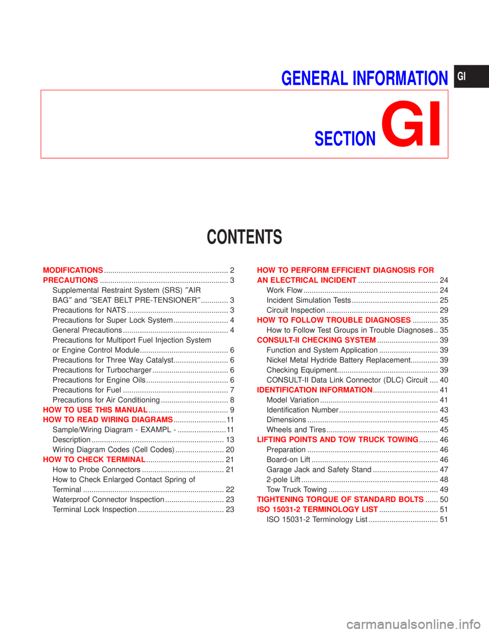
GENERAL INFORMATION
SECTION
GI
CONTENTS
MODIFICATIONS........................................................... 2
PRECAUTIONS............................................................. 3
Supplemental Restraint System (SRS)²AIR
BAG²and²SEAT BELT PRE-TENSIONER²............. 3
Precautions for NATS ................................................ 3
Precautions for Super Lock System .......................... 4
General Precautions .................................................. 4
Precautions for Multiport Fuel Injection System
or Engine Control Module.......................................... 6
Precautions for Three Way Catalyst.......................... 6
Precautions for Turbocharger .................................... 6
Precautions for Engine Oils ....................................... 6
Precautions for Fuel .................................................. 7
Precautions for Air Conditioning ................................ 8
HOW TO USE THIS MANUAL...................................... 9
HOW TO READ WIRING DIAGRAMS......................... 11
Sample/Wiring Diagram - EXAMPL - ....................... 11
Description ............................................................... 13
Wiring Diagram Codes (Cell Codes) ....................... 20
HOW TO CHECK TERMINAL..................................... 21
How to Probe Connectors ....................................... 21
How to Check Enlarged Contact Spring of
Terminal ................................................................... 22
Waterproof Connector Inspection ............................ 23
Terminal Lock Inspection ......................................... 23HOW TO PERFORM EFFICIENT DIAGNOSIS FOR
AN ELECTRICAL INCIDENT...................................... 24
Work Flow ................................................................ 24
Incident Simulation Tests ......................................... 25
Circuit Inspection ..................................................... 29
HOW TO FOLLOW TROUBLE DIAGNOSES............ 35
How to Follow Test Groups in Trouble Diagnoses .. 35
CONSULT-II CHECKING SYSTEM............................. 39
Function and System Application ............................ 39
Nickel Metal Hydride Battery Replacement............. 39
Checking Equipment................................................ 39
CONSULT-II Data Link Connector (DLC) Circuit .... 40
IDENTIFICATION INFORMATION............................... 41
Model Variation ........................................................ 41
Identification Number ............................................... 43
Dimensions .............................................................. 45
Wheels and Tires ..................................................... 45
LIFTING POINTS AND TOW TRUCK TOWING......... 46
Preparation .............................................................. 46
Board-on Lift ............................................................ 46
Garage Jack and Safety Stand ............................... 47
2-pole Lift ................................................................. 48
Tow Truck Towing .................................................... 49
TIGHTENING TORQUE OF STANDARD BOLTS...... 50
ISO 15031-2 TERMINOLOGY LIST............................ 51
ISO 15031-2 Terminology List ................................. 51
GI
Page 1806 of 2267
Sample/Wiring Diagram Ð EXAMPL Ð
lFor Description, refer to GI-13.
YGI001
Refer to optional splice. BATTERY
Preceding
page
RELAY
MOTOR
MOTOR
CONTROL
MODULE
A/T models
M/T models
.REFER TO THE FOLLOWINGM1,E103FUSE BLOCK -
Junction Box (J/B)
M2FUSE BLOCK -
Junction Box (J/B)
E127FUSE BLOCK -
Junction Box (J/B) POWER JOINT
CONNECTOR-1
SWITCHTo EL-
EXAMPL
Next page
To GI-
EXAMPL-04
DIODE
POSITION
APOSITION
BSIGNAL
GND GNDUNIT
HOW TO READ WIRING DIAGRAMS
GI-11