Page 642 of 2267
Diagnostic ProcedureNCEC0178
1 RETIGHTEN GROUND SCREWS
1. Turn ignition switch ªOFFº.
2. Loosen and retighten engine ground screws.
SEF994W
©GO TO 2.
2 CHECK INPUT SIGNAL CIRCUIT
1. Disconnect heated oxygen sensor 2 (rear) harness connector and ECM harness connector.
SEF033X
2. Check harness continuity between ECM terminal 63 and heated oxygen sensor 2 (rear) harness connector terminal 2.
Refer to wiring diagram.
Continuity should exist.
3. Check harness continuity between ECM terminal 63 [or heated oxygen sensor 2 (rear) harness connector terminal 2]
and ground.
Continuity should not exist.
4. Also check harness for short to ground and short to power.
OK or NG
OK©GO TO 4.
NG©GO TO 3.
3 DETECT MALFUNCTIONING PART
Check the harness for open or short between heated oxygen sensor 2 (rear) and ECM.
©Repair open circuit or short to ground or short to power in harness or connectors.
DTC P0140 HEATED OXYGEN SENSOR 2 (REAR)
(HIGH VOLTAGE)QG16I18DE
Diagnostic Procedure
EC-200
Page 643 of 2267

4 CHECK GROUND CIRCUIT
1. Check harness continuity between heated oxygen sensor 2 (rear) harness connector terminal 3 and engine ground.
Refer to wiring diagram.
Continuity should exist.
2. Also check harness for short to power.
OK or NG
OK©GO TO 5.
NG©Repair open circuit or short to power in harness or connectors.
5 CHECK HARNESS CONNECTOR
Check heated oxygen sensor 2 (rear) harness connector for water.
Water should not exist.
OK or NG
OK©GO TO 6.
NG©Repair or replace harness connector.
6 CHECK HEATED OXYGEN SENSOR 2 (REAR)
Refer to ªComponent Inspectionº, EC-QG-201.
OK or NG
OK©GO TO 7.
NG©Replace heated oxygen sensor 2 (rear).
7 CHECK INTERMITTENT INCIDENT
Perform ªTROUBLE DIAGNOSIS FOR INTERMITTENT INCIDENTº, EC-QG-102.
©INSPECTION END
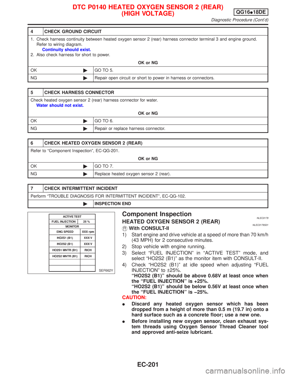
Component InspectionNLEC0179HEATED OXYGEN SENSOR 2 (REAR)NLEC0179S01With CONSULT-II
1) Start engine and drive vehicle at a speed of more than 70 km/h
(43 MPH) for 2 consecutive minutes.
2) Stop vehicle with engine running.
3) Select ªFUEL INJECTIONº in ªACTIVE TESTº mode, and
select ªHO2S2 (B1)º as the monitor item with CONSULT-II.
4) Check ªHO2S2 (B1)º at idle speed when adjusting ªFUEL
INJECTIONº to 25%.
ªHO2S2 (B1)º should be above 0.68V at least once when
the ªFUEL INJECTIONº is +25%.
ªHO2S2 (B1)º should be below 0.56V at least once when
the ªFUEL INJECTIONº is þ25%.
CAUTION:
IDiscard any heated oxygen sensor which has been
dropped from a height of more than 0.5 m (19.7 in) onto a
hard surface such as a concrete floor; use a new one.
IBefore installing new oxygen sensor, clean exhaust sys-
tem threads using Oxygen Sensor Thread Cleaner tool
and approved anti-seize lubricant.
SEF662Y
DTC P0140 HEATED OXYGEN SENSOR 2 (REAR)
(HIGH VOLTAGE)QG16I18DE
Diagnostic Procedure (Cont'd)
EC-201
Page 647 of 2267
Wiring DiagramNCEC0185
YEC068A
DTC P0141 HEATED OXYGEN SENSOR 2 HEATER
(REAR)QG16I18DE
Wiring Diagram
EC-205
Page 648 of 2267
Diagnostic ProcedureNCEC0186
1 CHECK POWER SUPPLY
1. Turn ignition switch ªOFFº.
2. Disconnect heated oxygen sensor 2 (rear) harness connector.
SEF033X3. Turn ignition switch ªONº.
4. Check voltage between terminal 4 and ground.
SEF047XVoltage: Battery voltage
OK or NG
OK©GO TO 3.
NG©GO TO 2.
2 DETECT MALFUNCTIONING PART
Check the following.
IHarness connectors F104, M50
IHarness for open or short between heated oxygen sensor 2 (rear) and fuse
I10A fuse
©Repair harness or connectors.
3 CHECK OUTPUT SIGNAL CIRCUIT
1. Turn ignition switch ªOFFº.
2. Disconnect ECM harness connector.
3. Check harness continuity between heated oxygen sensor 2 (rear) harness connector terminal 1 and ECM terminal 3.
Refer to wiring diagram.
Continuity should exist.
4. Also check harness for short to ground and short to power.
OK or NG
OK©GO TO 5.
NG©GO TO 4.
DTC P0141 HEATED OXYGEN SENSOR 2 HEATER
(REAR)QG16I18DE
Diagnostic Procedure
EC-206
Page 652 of 2267
Wiring DiagramNCEC0190
YEC069A
DTC P0171 FUEL INJECTION SYSTEM FUNCTION
(LEAN SIDE)QG16I18DE
Wiring Diagram
EC-210
Page 653 of 2267

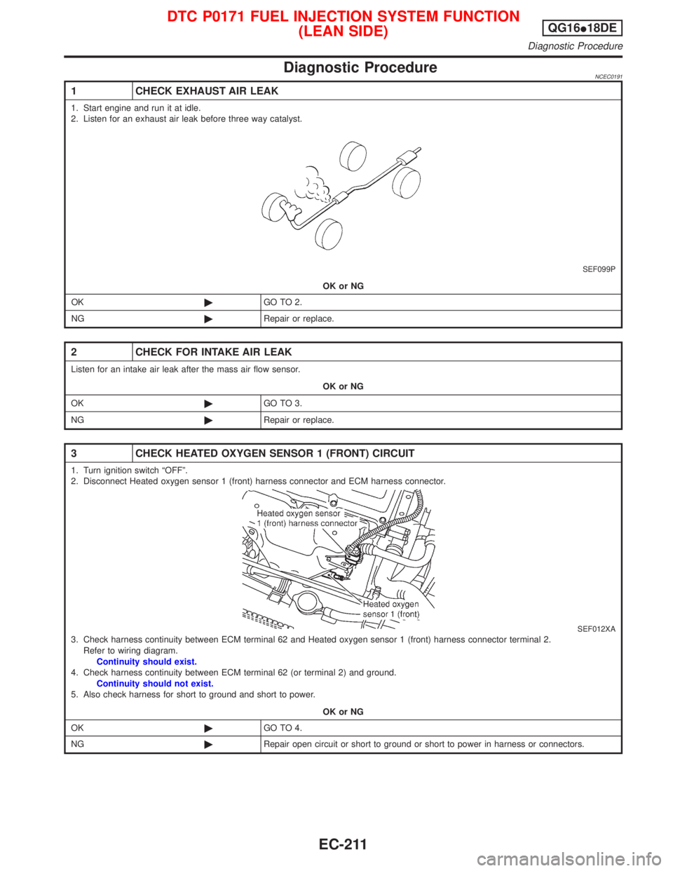
Diagnostic ProcedureNCEC0191
1 CHECK EXHAUST AIR LEAK
1. Start engine and run it at idle.
2. Listen for an exhaust air leak before three way catalyst.
SEF099P
OK or NG
OK©GO TO 2.
NG©Repair or replace.
2 CHECK FOR INTAKE AIR LEAK
Listen for an intake air leak after the mass air flow sensor.
OK or NG
OK©GO TO 3.
NG©Repair or replace.
3 CHECK HEATED OXYGEN SENSOR 1 (FRONT) CIRCUIT
1. Turn ignition switch ªOFFº.
2. Disconnect Heated oxygen sensor 1 (front) harness connector and ECM harness connector.
SEF012XA3. Check harness continuity between ECM terminal 62 and Heated oxygen sensor 1 (front) harness connector terminal 2.
Refer to wiring diagram.
Continuity should exist.
4. Check harness continuity between ECM terminal 62 (or terminal 2) and ground.
Continuity should not exist.
5. Also check harness for short to ground and short to power.
OK or NG
OK©GO TO 4.
NG©Repair open circuit or short to ground or short to power in harness or connectors.
DTC P0171 FUEL INJECTION SYSTEM FUNCTION
(LEAN SIDE)QG16I18DE
Diagnostic Procedure
EC-211
Page 659 of 2267
Wiring DiagramNCEC0194
YEC069A
DTC P0172 FUEL INJECTION SYSTEM FUNCTION
(RICH SIDE)QG16I18DE
Wiring Diagram
EC-217
Page 660 of 2267
Diagnostic ProcedureNCEC0195
1 CHECK FOR EXHAUST AIR LEAK
1. Start engine and run it at idle.
2. Listen for an exhaust air leak before the three way catalyst.
SEF099P
OK or NG
OK©GO TO 2.
NG©Repair or replace.
2 CHECK HEATED OXYGEN SENSOR 1 (FRONT) CIRCUIT
1. Turn ignition switch ªOFFº.
2. Disconnect Heated oxygen sensor 1 (front) harness connector and ECM harness connector.
SEF012XA3. Check harness continuity between ECM terminal 62 and Heated oxygen sensor 1 (front) harness connector terminal 2.
Refer to wiring diagram.
Continuity should exist.
4. Check harness continuity between ECM terminal 62 (or terminal 2) and ground.
Continuity should not exist.
5. Also check harness for short to ground and short to power.
OK or NG
OK©GO TO 3.
NG©Repair open circuit or short to ground or short to power in harness or connectors.
DTC P0172 FUEL INJECTION SYSTEM FUNCTION
(RICH SIDE)QG16I18DE
Diagnostic Procedure
EC-218