Page 460 of 2267
System DiagramNCEC0011
YEC116A
ENGINE AND EMISSION CONTROL OVERALL SYSTEMQG16I18DE
System Diagram
EC-18
Page 461 of 2267
Vacuum Hose DrawingNCEC0012Refer to ªSystem Diagramº on EC-QG-18 for vacuum control system.
NEF231A Fuel pressure
regulator
EVAP canister purge
pipe (to EVAP
canister)
To air duct To air control valve
(Power steering)
EVAP canister purge volume
control solenoid valve
EVAP canister
Air
Fuel tank
ENGINE AND EMISSION CONTROL OVERALL SYSTEMQG16I18DE
Vacuum Hose Drawing
EC-19
Page 545 of 2267
Main Power Supply and Ground Circuit
WIRING DIAGRAMNCEC0047
YEC770
BATTERY
Refer to EL-POWER.
OFF
ACCST
ONIGNITION
SWITCH
FUSE
BLOCK
(J/B)
To EC-IGN/SG,
EC-TP/SW,
EC-AAC/V,
EC-EGR,
EC-EGVC/V ECM RELAY
: Detectable line for DTC
: Non-detectable line for DTC
Refer to last page (Foldout page) ECM
TROUBLE DIAGNOSIS FOR POWER SUPPLYQG16I18DE
Main Power Supply and Ground Circuit
EC-103
Page 547 of 2267
2 CHECK POWER SUPPLY-I
1. Turn ignition switch ªOFFº and then ªONº.
2. Check voltage between ECM terminal 43 and ground with CONSULT-II or tester.
SEF981WVoltage: Battery voltage
OK or NG
OK©GO TO 9.
NG©GO TO 3.
3 DETECT MALFUNCTIONING PART
Check the following.
I10A Fuse
I40A fusible link
IHarness connectors M50, F104
IHarness for open or short between ECM and fuse block
IHarness for open or short between fuse block and ignition switch
©Repair harness or connectors.
4 CHECK ECM GROUND CIRCUIT FOR OPEN AND SHORT-I
1. Turn ignition switch ªOFFº.
2. Disconnect ECM harness connector.
3. Check harness continuity between ECM terminals 48, 57, 106, 108 and engine ground.
Refer to WIRING DIAGRAM.
Continuity should exist.
4. Also check harness for short to power.
OK or NG
OK©GO TO 5.
NG©Repair open circuit or short to power in harness or connectors.
TROUBLE DIAGNOSIS FOR POWER SUPPLYQG16I18DE
Main Power Supply and Ground Circuit (Cont'd)
EC-105
Page 550 of 2267
12 CHECK HARNESS CONTINUITY BETWEEN ECM RELAY AND ECM
1. Disconnect ECM harness connector.
2. Disconnect ECM relay.
SEF984W3. Check harness continuity between ECM terminals 110, 112 and relay terminal 5.
Refer to wiring diagram.
Continuity should exist.
4. Also check harness for short to ground and short to power.
OK or NG
OK©GO TO 14.
NG©GO TO 13.
13 DETECT MALFUNCTIONING PART
Check the following.
IHarness connectors E90, F73
IHarness for open or short between ECM relay and ECM
©Repair open circuit or short to ground or short to power in harness or connectors.
14 CHECK VOLTAGE BETWEEN ECM RELAY AND GROUND
Check voltage between relay terminals 1, 3 and ground with CONSULT-II or tester.
SEF985WVoltage: Battery voltage
OK or NG
OK©GO TO 16.
NG©GO TO 15.
15 DETECT MALFUNCTIONING PART
Check the harness for open or short between ECM relay and fuse.
©Repair harness or connectors.
TROUBLE DIAGNOSIS FOR POWER SUPPLYQG16I18DE
Main Power Supply and Ground Circuit (Cont'd)
EC-108
Page 551 of 2267
16 CHECK ECM RELAY
1. Apply 12V direct current between relay terminals 1 and 2.
2. Check continuity between relay terminals 3 and 5, 6 and 7.
SEC202BC12V (1 - 2) applied: Continuity exists.
No voltage applied: No continuity
OK or NG
OK©GO TO 17.
NG©Replace ECM relay.
17 CHECK GROUND CIRCUIT
1. Turn ignition switch ªOFFº.
2. Disconnect ECM harness connector.
3. Check harness continuity between ECM terminals 48, 57, 106, 108 and engine ground.
Refer to wiring diagram.
Continuity should exist.
4. Also check harness for short to ground and short to power.
OK or NG
OK©GO TO 18.
NG©Repair open circuit or short to ground or short to power in harness or connectors.
18 CHECK INTERMITTENT INCIDENT
Perform ªTROUBLE DIAGNOSIS FOR INTERMITTENT INCIDENTº, EC-QG-102.
©INSPECTION END
TROUBLE DIAGNOSIS FOR POWER SUPPLYQG16I18DE
Main Power Supply and Ground Circuit (Cont'd)
EC-109
Page 554 of 2267
Wiring DiagramNCEC0056
YEC063A
DTC P0100 MASS AIR FLOW SENSOR (MAFS)QG16I18DE
Wiring Diagram
EC-112
Page 556 of 2267

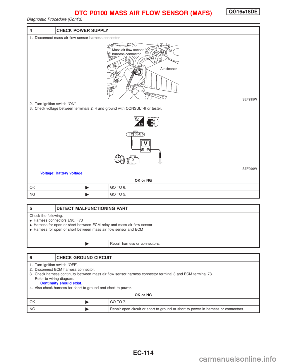
4 CHECK POWER SUPPLY
1. Disconnect mass air flow sensor harness connector.
SEF995W2. Turn ignition switch ªONº.
3. Check voltage between terminals 2, 4 and ground with CONSULT-II or tester.
SEF996WVoltage: Battery voltage
OK or NG
OK©GO TO 6.
NG©GO TO 5.
5 DETECT MALFUNCTIONING PART
Check the following.
IHarness connectors E90, F73
IHarness for open or short between ECM relay and mass air flow sensor
IHarness for open or short between mass air flow sensor and ECM
©Repair harness or connectors.
6 CHECK GROUND CIRCUIT
1. Turn ignition switch ªOFFº.
2. Disconnect ECM harness connector.
3. Check harness continuity between mass air flow sensor harness connector terminal 3 and ECM terminal 73.
Refer to wiring diagram.
Continuity should exist.
4. Also check harness for short to ground and short to power.
OK or NG
OK©GO TO 7.
NG©Repair open circuit or short to ground or short to power in harness or connectors.
DTC P0100 MASS AIR FLOW SENSOR (MAFS)QG16I18DE
Diagnostic Procedure (Cont'd)
EC-114