1999 NISSAN PRIMERA diagram
[x] Cancel search: diagramPage 98 of 2267
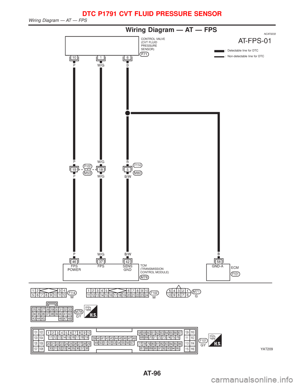
Wiring Diagram Ð AT Ð FPSNCAT0233
YAT209
TCM
(TRANSMISSION
CONTROL MODULE): Detectable line for DTC
: Non-detectable line for DTC CONTROL VALVE
(CVT FLUID
PRESSURE
SENSOR)ECM
DTC P1791 CVT FLUID PRESSURE SENSOR
Wiring Diagram Ð AT Ð FPS
AT-96
Page 109 of 2267
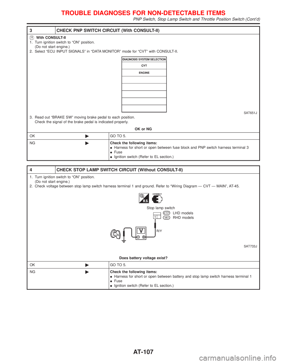
3 CHECK PNP SWITCH CIRCUIT (With CONSULT-II)
With CONSULT-II
1. Turn ignition switch to ªONº position.
(Do not start engine.)
2. Select ªECU INPUT SIGNALSº in ªDATA MONITORº mode for ªCVTº with CONSULT-II.
SAT651J3. Read out ªBRAKE SWº moving brake pedal to each position.
Check the signal of the brake pedal is indicated properly.
OK or NG
OK©GO TO 5.
NG©Check the following items:
IHarness for short or open between fuse block and PNP switch harness terminal 3
IFuse
IIgnition switch (Refer to EL section.)
4 CHECK STOP LAMP SWITCH CIRCUIT (Without CONSULT-II)
1. Turn ignition switch to ªONº position.
(Do not start engine.)
2. Check voltage between stop lamp switch harness terminal 1 and ground. Refer to ªWiring Diagram Ð CVT Ð MAINº, AT-45.
SAT733J
Stop lamp switch
LHD models
RHD models
Does battery voltage exist?
OK©GO TO 5.
NG©Check the following items:
IHarness for short or open between battery and stop lamp switch harness terminal 1
IFuse
IIgnition switch (Refer to EL section.)
TROUBLE DIAGNOSES FOR NON-DETECTABLE ITEMS
PNP Switch, Stop Lamp Switch and Throttle Position Switch (Cont'd)
AT-107
Page 112 of 2267
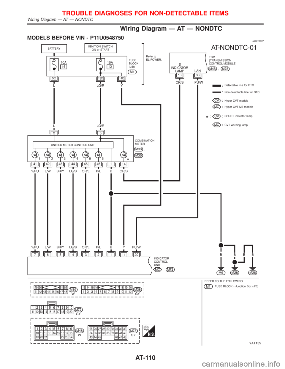
Wiring Diagram Ð AT Ð NONDTC
MODELS BEFORE VIN - P11U0548750NCAT0237
YAT155
BATTERYIGNITION SWITCH
ON or START
FUSE
BLOCK
(J/B)Refer to
EL-POWER.TCM
(TRANSMISSION
CONTROL MODULE)
Detectable line for DTC
Non-detectable line for DTC
Hyper CVT models
Hyper CVT M6 models
SPORT indicator lamp
CVT warning lamp
UNIFIED METER CONTROL UNITCOMBINATION
METER
INDICATOR
CONTROL
UNIT
REFER TO THE FOLLOWING
FUSE BLOCK - Junction Box (J/B)
TROUBLE DIAGNOSES FOR NON-DETECTABLE ITEMS
Wiring Diagram Ð AT Ð NONDTC
AT-110
Page 113 of 2267

MODELS AFTER VIN - P11U0548750
YAT253
TROUBLE DIAGNOSES FOR NON-DETECTABLE ITEMS
Wiring Diagram Ð AT Ð NONDTC (Cont'd)
AT - 111
Page 114 of 2267

YAT254
TROUBLE DIAGNOSES FOR NON-DETECTABLE ITEMS
Wiring Diagram Ð AT Ð NONDTC (Cont'd)
AT-112
Page 115 of 2267

YAT255
TROUBLE DIAGNOSES FOR NON-DETECTABLE ITEMS
Wiring Diagram Ð AT Ð NONDTC (Cont'd)
AT-113
Page 123 of 2267
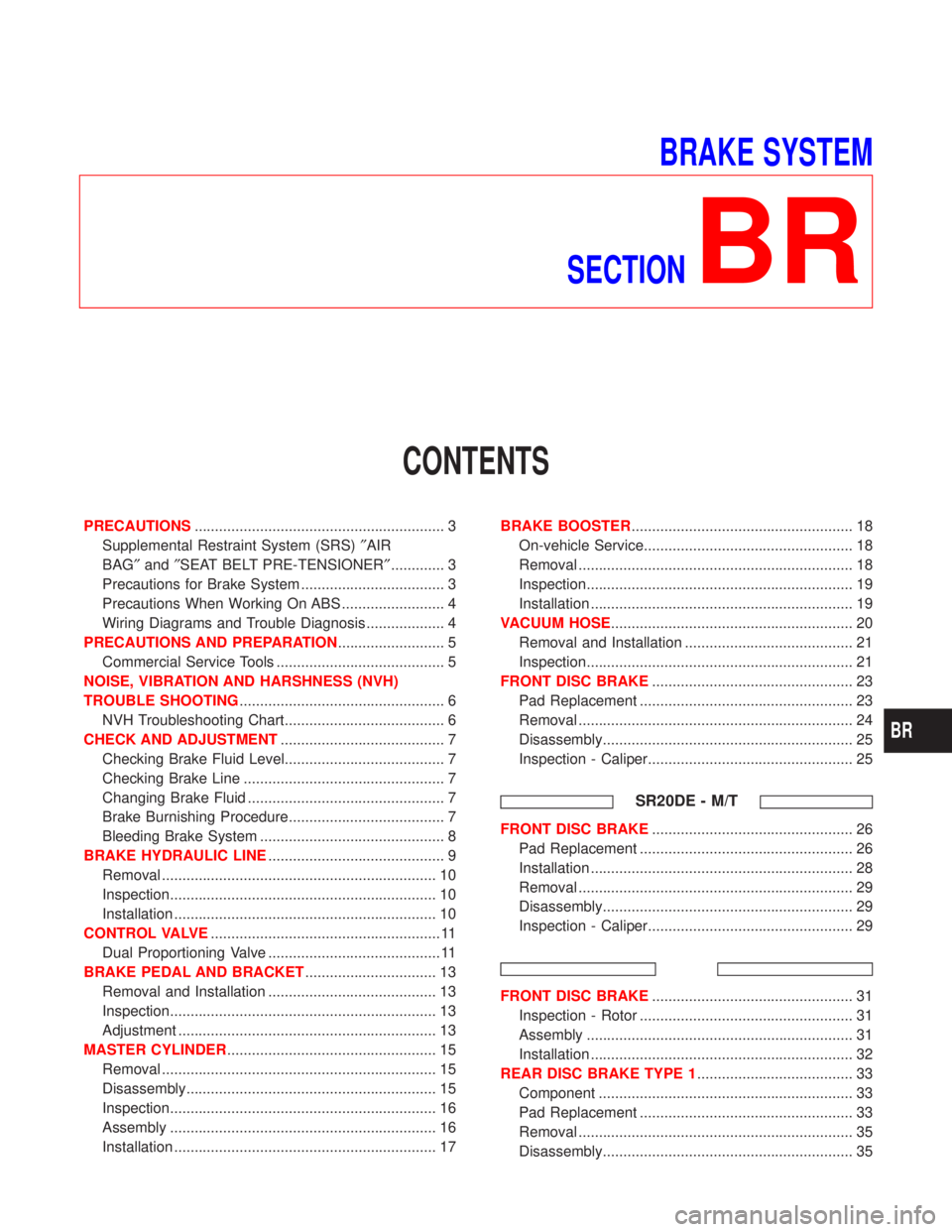
BRAKE SYSTEM
SECTION
BR
CONTENTS
PRECAUTIONS............................................................. 3
Supplemental Restraint System (SRS)²AIR
BAG²and²SEAT BELT PRE-TENSIONER²............. 3
Precautions for Brake System ................................... 3
Precautions When Working On ABS ......................... 4
Wiring Diagrams and Trouble Diagnosis ................... 4
PRECAUTIONS AND PREPARATION.......................... 5
Commercial Service Tools ......................................... 5
NOISE, VIBRATION AND HARSHNESS (NVH)
TROUBLE SHOOTING.................................................. 6
NVH Troubleshooting Chart....................................... 6
CHECK AND ADJUSTMENT........................................ 7
Checking Brake Fluid Level....................................... 7
Checking Brake Line ................................................. 7
Changing Brake Fluid ................................................ 7
Brake Burnishing Procedure...................................... 7
Bleeding Brake System ............................................. 8
BRAKE HYDRAULIC LINE........................................... 9
Removal ................................................................... 10
Inspection................................................................. 10
Installation ................................................................ 10
CONTROL VALVE........................................................ 11
Dual Proportioning Valve .......................................... 11
BRAKE PEDAL AND BRACKET................................ 13
Removal and Installation ......................................... 13
Inspection................................................................. 13
Adjustment ............................................................... 13
MASTER CYLINDER................................................... 15
Removal ................................................................... 15
Disassembly............................................................. 15
Inspection................................................................. 16
Assembly ................................................................. 16
Installation ................................................................ 17BRAKE BOOSTER...................................................... 18
On-vehicle Service................................................... 18
Removal ................................................................... 18
Inspection................................................................. 19
Installation ................................................................ 19
VACUUM HOSE........................................................... 20
Removal and Installation ......................................... 21
Inspection................................................................. 21
FRONT DISC BRAKE................................................. 23
Pad Replacement .................................................... 23
Removal ................................................................... 24
Disassembly............................................................. 25
Inspection - Caliper.................................................. 25
SR20DE - M/T
FRONT DISC BRAKE................................................. 26
Pad Replacement .................................................... 26
Installation ................................................................ 28
Removal ................................................................... 29
Disassembly............................................................. 29
Inspection - Caliper.................................................. 29
FRONT DISC BRAKE................................................. 31
Inspection - Rotor .................................................... 31
Assembly ................................................................. 31
Installation ................................................................ 32
REAR DISC BRAKE TYPE 1...................................... 33
Component .............................................................. 33
Pad Replacement .................................................... 33
Removal ................................................................... 35
Disassembly............................................................. 35
BR
Page 124 of 2267
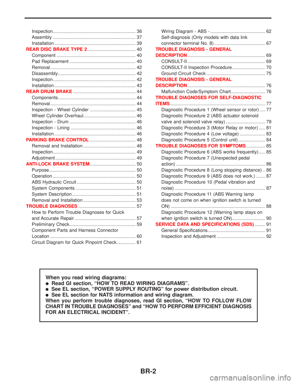
Inspection................................................................. 36
Assembly ................................................................. 37
Installation ................................................................ 39
REAR DISC BRAKE TYPE 2...................................... 40
Component .............................................................. 40
Pad Replacement .................................................... 40
Removal ................................................................... 42
Disassembly............................................................. 42
Inspection................................................................. 42
Installation ................................................................ 43
REAR DRUM BRAKE................................................. 44
Components............................................................. 44
Removal ................................................................... 44
Inspection - Wheel Cylinder .................................... 45
Wheel Cylinder Overhaul......................................... 46
Inspection - Drum .................................................... 46
Inspection - Lining ................................................... 46
Installation ................................................................ 46
PARKING BRAKE CONTROL.................................... 48
Removal and Installation ......................................... 48
Inspection................................................................. 49
Adjustment ............................................................... 49
ANTI-LOCK BRAKE SYSTEM.................................... 50
Purpose.................................................................... 50
Operation ................................................................. 50
ABS Hydraulic Circuit .............................................. 50
System Components ............................................... 51
System Description .................................................. 51
Removal and Installation ......................................... 53
TROUBLE DIAGNOSES............................................. 57
How to Perform Trouble Diagnoses for Quick
and Accurate Repair ................................................ 57
Preliminary Check.................................................... 59
Component Parts and Harness Connector
Location ................................................................... 60
Circuit Diagram for Quick Pinpoint Check............... 61Wiring Diagram - ABS - ........................................... 62
Self-diagnosis (Only models with data link
connector terminal No. 8) ........................................ 67
TROUBLE DIAGNOSIS - GENERAL
DESCRIPTION............................................................. 69
CONSULT-II ............................................................. 69
CONSULT-II Inspection Procedure.......................... 70
Ground Circuit Check .............................................. 75
TROUBLE DIAGNOSIS - GENERAL
DESCRIPTION............................................................. 76
Malfunction Code/Symptom Chart........................... 76
TROUBLE DIAGNOSES FOR SELF-DIAGNOSTIC
ITEMS........................................................................... 77
Diagnostic Procedure 1 (Wheel sensor or rotor) .... 77
Diagnostic Procedure 2 (ABS actuator solenoid
valve and solenoid valve relay) ............................... 79
Diagnostic Procedure 3 (Motor Relay or motor) ..... 81
Diagnostic Procedure 4 (Low voltage) .................... 83
Diagnostic Procedure 5 (Control unit) ..................... 84
TROUBLE DIAGNOSES FOR SYMPTOMS............... 85
Diagnostic Procedure 6 (ABS works frequently) ..... 85
Diagnostic Procedure 7 (Unexpected pedal
action) ...................................................................... 86
Diagnostic Procedure 8 (Long stopping distance) .. 86
Diagnostic Procedure 9 (ABS does not work.) ....... 87
Diagnostic Procedure 10 (Pedal vibration and
noise) ....................................................................... 87
Diagnostic Procedure 11 (ABS Warning lamp
does not come on when ignition switch is turned
ON) .......................................................................... 88
Diagnostic Procedure 12 (Warning lamp stays on
when ignition switch is turned ON).......................... 90
SERVICE DATA AND SPECIFICATIONS (SDS)........ 91
General Specifications ............................................. 91
Inspection and Adjustment ...................................... 92
When you read wiring diagrams:
lRead GI section, ªHOW TO READ WIRING DIAGRAMSº.
lSee EL section, ªPOWER SUPPLY ROUTINGº for power distribution circuit.
lSee EL section for NATS information and wiring diagram.
When you perform trouble diagnoses, read GI section, ªHOW TO FOLLOW FLOW
CHART IN TROUBLE DIAGNOSESº and ªHOW TO PERFORM EFFICIENT DIAGNOSIS
FOR AN ELECTRICAL INCIDENTº.
BR-2