1999 NISSAN PRIMERA parking brake
[x] Cancel search: parking brakePage 13 of 2267
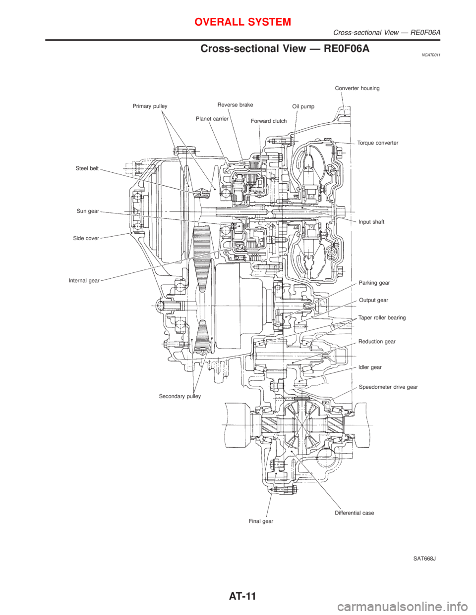
Cross-sectional View Ð RE0F06ANCAT0011
SAT668J Primary pulley
Steel belt
Sun gear
Side cover
Internal gear
Secondary pulley
Final gearDifferential caseSpeedometer drive gear Idler gear Reduction gear Taper roller bearingOutput gear Parking gear Input shaft Torque converter Converter housing
Oil pump
Forward clutch Reverse brake
Planet carrier
OVERALL SYSTEM
Cross-sectional View Ð RE0F06A
AT-11
Page 37 of 2267
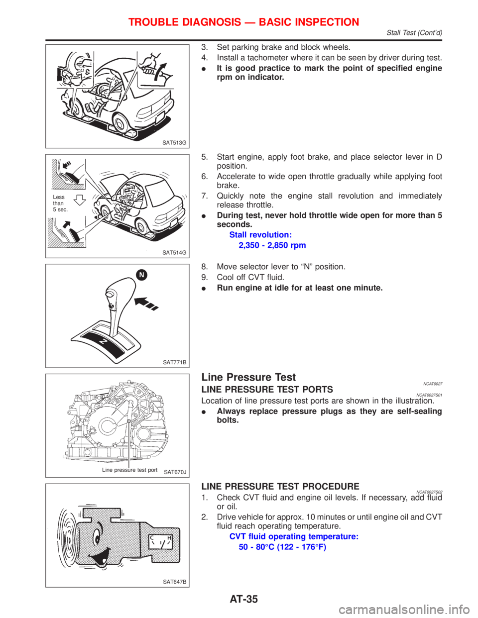
3. Set parking brake and block wheels.
4. Install a tachometer where it can be seen by driver during test.
IIt is good practice to mark the point of specified engine
rpm on indicator.
5. Start engine, apply foot brake, and place selector lever in D
position.
6. Accelerate to wide open throttle gradually while applying foot
brake.
7. Quickly note the engine stall revolution and immediately
release throttle.
IDuring test, never hold throttle wide open for more than 5
seconds.
Stall revolution:
2,350 - 2,850 rpm
8. Move selector lever to ªNº position.
9. Cool off CVT fluid.
IRun engine at idle for at least one minute.
Line Pressure TestNCAT0027LINE PRESSURE TEST PORTSNCAT0027S01Location of line pressure test ports are shown in the illustration.
IAlways replace pressure plugs as they are self-sealing
bolts.
LINE PRESSURE TEST PROCEDURENCAT0027S021. Check CVT fluid and engine oil levels. If necessary, add fluid
or oil.
2. Drive vehicle for approx. 10 minutes or until engine oil and CVT
fluid reach operating temperature.
CVT fluid operating temperature:
50 - 80ÉC (122 - 176ÉF)
SAT513G
SAT514G Less
than
5 sec.
SAT771B
SAT670J Line pressure test port
SAT647B
TROUBLE DIAGNOSIS Ð BASIC INSPECTION
Stall Test (Cont'd)
AT-35
Page 38 of 2267
3. Install pressure gauge to corresponding line pressure port.
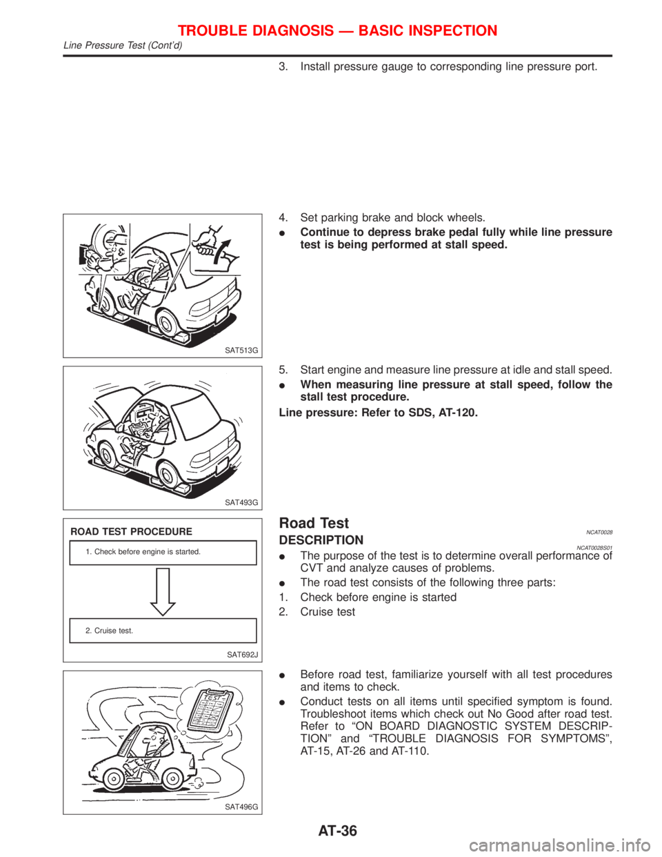
4. Set parking brake and block wheels.
IContinue to depress brake pedal fully while line pressure
test is being performed at stall speed.
5. Start engine and measure line pressure at idle and stall speed.
IWhen measuring line pressure at stall speed, follow the
stall test procedure.
Line pressure: Refer to SDS, AT-120.
Road TestNCAT0028DESCRIPTIONNCAT0028S01IThe purpose of the test is to determine overall performance of
CVT and analyze causes of problems.
IThe road test consists of the following three parts:
1. Check before engine is started
2. Cruise test
IBefore road test, familiarize yourself with all test procedures
and items to check.
IConduct tests on all items until specified symptom is found.
Troubleshoot items which check out No Good after road test.
Refer to ªON BOARD DIAGNOSTIC SYSTEM DESCRIP-
TIONº and ªTROUBLE DIAGNOSIS FOR SYMPTOMSº,
AT-15, AT-26 and AT-110.
SAT513G
SAT493G
SAT692J
ROAD TEST PROCEDURE
1. Check before engine is started.
2. Cruise test.
SAT496G
TROUBLE DIAGNOSIS Ð BASIC INSPECTION
Line Pressure Test (Cont'd)
AT-36
Page 119 of 2267
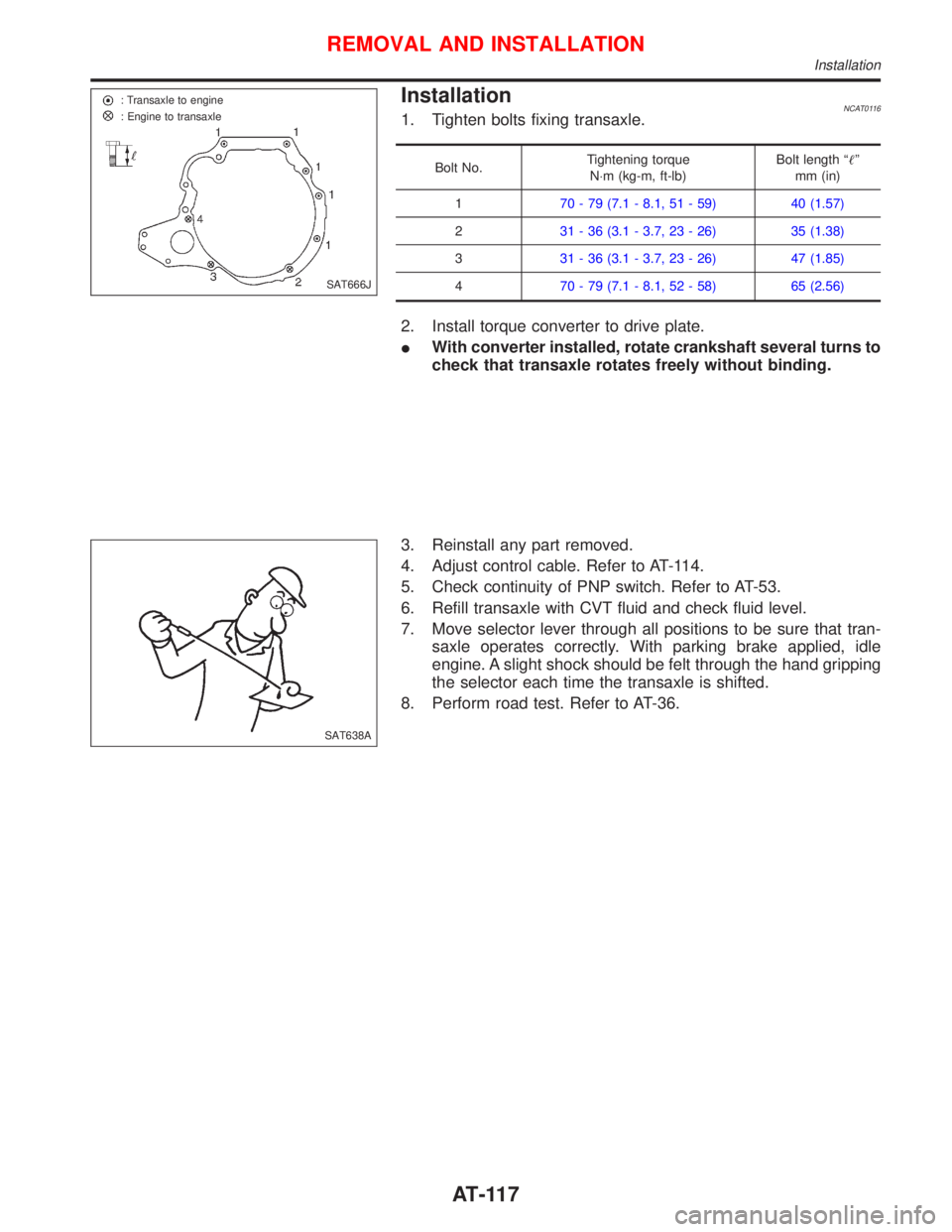
InstallationNCAT01161. Tighten bolts fixing transaxle.
Bolt No.Tightening torque
N×m (kg-m, ft-lb)Bolt length ªº
mm (in)
170 - 79 (7.1 - 8.1, 51 - 59) 40 (1.57)
231 - 36 (3.1 - 3.7, 23 - 26) 35 (1.38)
331 - 36 (3.1 - 3.7, 23 - 26) 47 (1.85)
470 - 79 (7.1 - 8.1, 52 - 58) 65 (2.56)
2. Install torque converter to drive plate.
IWith converter installed, rotate crankshaft several turns to
check that transaxle rotates freely without binding.
3. Reinstall any part removed.
4. Adjust control cable. Refer to AT-114.
5. Check continuity of PNP switch. Refer to AT-53.
6. Refill transaxle with CVT fluid and check fluid level.
7. Move selector lever through all positions to be sure that tran-
saxle operates correctly. With parking brake applied, idle
engine. A slight shock should be felt through the hand gripping
the selector each time the transaxle is shifted.
8. Perform road test. Refer to AT-36.
SAT666J : Transaxle to engine
: Engine to transaxle
SAT638A
REMOVAL AND INSTALLATION
Installation
AT-117
Page 124 of 2267
Inspection................................................................. 36
Assembly ................................................................. 37
Installation ................................................................ 39
REAR DISC BRAKE TYPE 2...................................... 40
Component .............................................................. 40
Pad Replacement .................................................... 40
Removal ................................................................... 42
Disassembly............................................................. 42
Inspection................................................................. 42
Installation ................................................................ 43
REAR DRUM BRAKE................................................. 44
Components............................................................. 44
Removal ................................................................... 44
Inspection - Wheel Cylinder .................................... 45
Wheel Cylinder Overhaul......................................... 46
Inspection - Drum .................................................... 46
Inspection - Lining ................................................... 46
Installation ................................................................ 46
PARKING BRAKE CONTROL.................................... 48
Removal and Installation ......................................... 48
Inspection................................................................. 49
Adjustment ............................................................... 49
ANTI-LOCK BRAKE SYSTEM.................................... 50
Purpose.................................................................... 50
Operation ................................................................. 50
ABS Hydraulic Circuit .............................................. 50
System Components ............................................... 51
System Description .................................................. 51
Removal and Installation ......................................... 53
TROUBLE DIAGNOSES............................................. 57
How to Perform Trouble Diagnoses for Quick
and Accurate Repair ................................................ 57
Preliminary Check.................................................... 59
Component Parts and Harness Connector
Location ................................................................... 60
Circuit Diagram for Quick Pinpoint Check............... 61Wiring Diagram - ABS - ........................................... 62
Self-diagnosis (Only models with data link
connector terminal No. 8) ........................................ 67
TROUBLE DIAGNOSIS - GENERAL
DESCRIPTION............................................................. 69
CONSULT-II ............................................................. 69
CONSULT-II Inspection Procedure.......................... 70
Ground Circuit Check .............................................. 75
TROUBLE DIAGNOSIS - GENERAL
DESCRIPTION............................................................. 76
Malfunction Code/Symptom Chart........................... 76
TROUBLE DIAGNOSES FOR SELF-DIAGNOSTIC
ITEMS........................................................................... 77
Diagnostic Procedure 1 (Wheel sensor or rotor) .... 77
Diagnostic Procedure 2 (ABS actuator solenoid
valve and solenoid valve relay) ............................... 79
Diagnostic Procedure 3 (Motor Relay or motor) ..... 81
Diagnostic Procedure 4 (Low voltage) .................... 83
Diagnostic Procedure 5 (Control unit) ..................... 84
TROUBLE DIAGNOSES FOR SYMPTOMS............... 85
Diagnostic Procedure 6 (ABS works frequently) ..... 85
Diagnostic Procedure 7 (Unexpected pedal
action) ...................................................................... 86
Diagnostic Procedure 8 (Long stopping distance) .. 86
Diagnostic Procedure 9 (ABS does not work.) ....... 87
Diagnostic Procedure 10 (Pedal vibration and
noise) ....................................................................... 87
Diagnostic Procedure 11 (ABS Warning lamp
does not come on when ignition switch is turned
ON) .......................................................................... 88
Diagnostic Procedure 12 (Warning lamp stays on
when ignition switch is turned ON).......................... 90
SERVICE DATA AND SPECIFICATIONS (SDS)........ 91
General Specifications ............................................. 91
Inspection and Adjustment ...................................... 92
When you read wiring diagrams:
lRead GI section, ªHOW TO READ WIRING DIAGRAMSº.
lSee EL section, ªPOWER SUPPLY ROUTINGº for power distribution circuit.
lSee EL section for NATS information and wiring diagram.
When you perform trouble diagnoses, read GI section, ªHOW TO FOLLOW FLOW
CHART IN TROUBLE DIAGNOSESº and ªHOW TO PERFORM EFFICIENT DIAGNOSIS
FOR AN ELECTRICAL INCIDENTº.
BR-2
Page 129 of 2267
Checking Brake Fluid Level
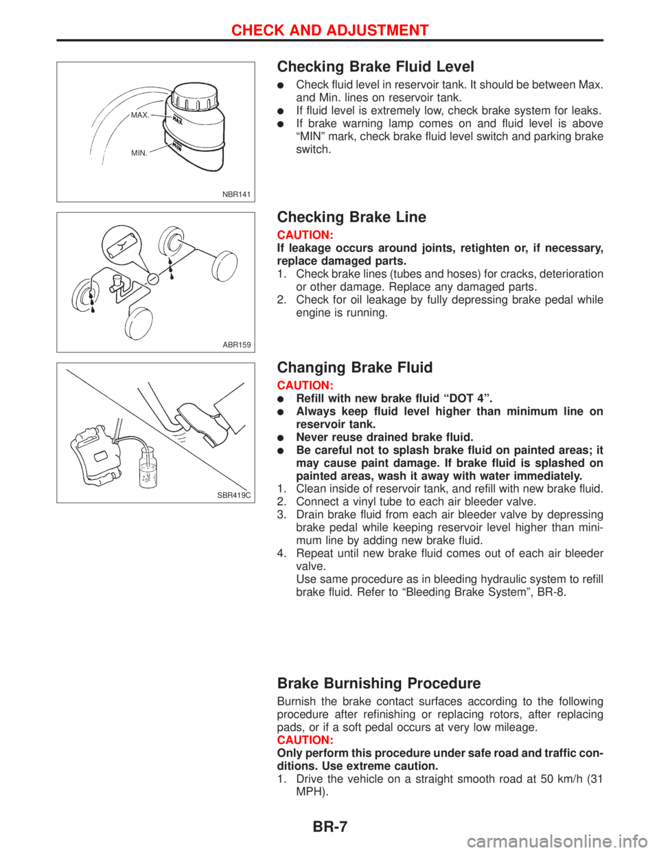
lCheck fluid level in reservoir tank. It should be between Max.
and Min. lines on reservoir tank.
lIf fluid level is extremely low, check brake system for leaks.
lIf brake warning lamp comes on and fluid level is above
ªMINº mark, check brake fluid level switch and parking brake
switch.
Checking Brake Line
CAUTION:
If leakage occurs around joints, retighten or, if necessary,
replace damaged parts.
1. Check brake lines (tubes and hoses) for cracks, deterioration
or other damage. Replace any damaged parts.
2. Check for oil leakage by fully depressing brake pedal while
engine is running.
Changing Brake Fluid
CAUTION:
lRefill with new brake fluid ªDOT 4º.
lAlways keep fluid level higher than minimum line on
reservoir tank.
lNever reuse drained brake fluid.
lBe careful not to splash brake fluid on painted areas; it
may cause paint damage. If brake fluid is splashed on
painted areas, wash it away with water immediately.
1. Clean inside of reservoir tank, and refill with new brake fluid.
2. Connect a vinyl tube to each air bleeder valve.
3. Drain brake fluid from each air bleeder valve by depressing
brake pedal while keeping reservoir level higher than mini-
mum line by adding new brake fluid.
4. Repeat until new brake fluid comes out of each air bleeder
valve.
Use same procedure as in bleeding hydraulic system to refill
brake fluid. Refer to ªBleeding Brake Systemº, BR-8.
Brake Burnishing Procedure
Burnish the brake contact surfaces according to the following
procedure after refinishing or replacing rotors, after replacing
pads, or if a soft pedal occurs at very low mileage.
CAUTION:
Only perform this procedure under safe road and traffic con-
ditions. Use extreme caution.
1. Drive the vehicle on a straight smooth road at 50 km/h (31
MPH).
NBR141 MAX.
MIN.
ABR159
SBR419C
CHECK AND ADJUSTMENT
BR-7
Page 156 of 2267
lIt is not necessary to remove connecting bolt except for
disassembly or replacement of caliper assembly. In this
case, suspend cylinder body with wire so as not to
stretch brake hose.
lBurnish the brake contact surfaces after refinishing or
replacing rotors, after replacing pads, or if a soft pedal
occurs at very low mileage.
Refer to ªBrake Burnishing Procedureº, ªCHECK AND
ADJUSTMENTº, BR-7.
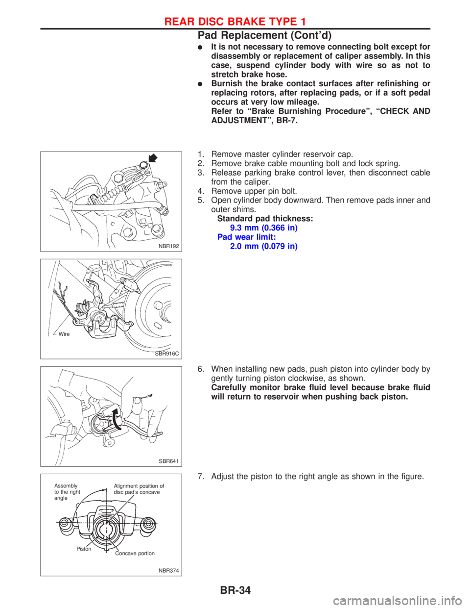
1. Remove master cylinder reservoir cap.
2. Remove brake cable mounting bolt and lock spring.
3. Release parking brake control lever, then disconnect cable
from the caliper.
4. Remove upper pin bolt.
5. Open cylinder body downward. Then remove pads inner and
outer shims.
Standard pad thickness:
9.3 mm (0.366 in)
Pad wear limit:
2.0 mm (0.079 in)
6. When installing new pads, push piston into cylinder body by
gently turning piston clockwise, as shown.
Carefully monitor brake fluid level because brake fluid
will return to reservoir when pushing back piston.
7. Adjust the piston to the right angle as shown in the figure.
NBR192
SBR916C Wire
SBR641
NBR374 Alignment position of
disc pad's concave
Concave portion Piston Assembly
to the right
angle
REAR DISC BRAKE TYPE 1
Pad Replacement (Cont'd)
BR-34
Page 157 of 2267
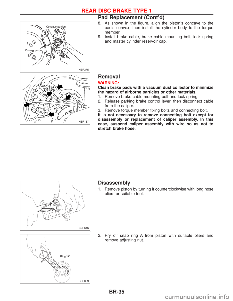
8. As shown in the figure, align the piston's concave to the
pad's convex, then install the cylinder body to the torque
member.
9. Install brake cable, brake cable mounting bolt, lock spring
and master cylinder reservoir cap.
Removal
WARNING:
Clean brake pads with a vacuum dust collector to minimize
the hazard of airborne particles or other materials.
1. Remove brake cable mounting bolt and lock spring.
2. Release parking brake control lever, then disconnect cable
from the caliper.
3. Remove torque member fixing bolts and connecting bolt.
It is not necessary to remove connecting bolt except for
disassembly or replacement of caliper assembly. In this
case, suspend caliper assembly with wire so as not to
stretch brake hose.
Disassembly
1. Remove piston by turning it counterclockwise with long nose
pliers or suitable tool.
2. Pry off snap ring A from piston with suitable pliers and
remove adjusting nut.
NBR375 Concave portion
Convex portion
NBR167
SBR646
SBR889 Ring ªAº
REAR DISC BRAKE TYPE 1
Pad Replacement (Cont'd)
BR-35