Page 163 of 2267
1. Remove master cylinder reservoir cap.
2. Remove brake cable lock spring.
3. Release parking brake control lever, then disconnect cable
from the caliper.
4. Remove upper pin bolt.
5. Open cylinder body downward. Then remove pad inner and
outer shims.
Standard pad thickness:
9.3 mm (0.366 in)
Pad wear limit:
2.0 mm (0.079 in)
6. When installing new pads, push piston into cylinder body by
gently turning piston clockwise, as shown.
Carefully monitor brake fluid level because brake fluid
will return to reservoir when pushing back piston.
7. Adjust the piston to the right angle as shown in the figure.
8. As shown in the figure, align the piston's concave to the
pad's convex, then install the cylinder body to the torque
member.
9. Install brake cable, brake cable mounting bolt, lock spring
and master cylinder reservoir cap.
NBR423
NBR426
SBR641
NBR374
NBR375
REAR DISC BRAKE TYPE 2
Pad Replacement (Cont'd)
BR-41
Page 164 of 2267

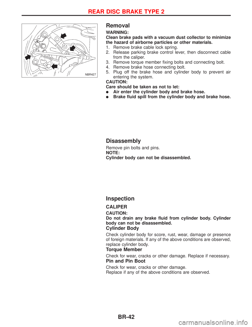
Removal
WARNING:
Clean brake pads with a vacuum dust collector to minimize
the hazard of airborne particles or other materials.
1. Remove brake cable lock spring.
2. Release parking brake control lever, then disconnect cable
from the caliper.
3. Remove torque member fixing bolts and connecting bolt.
4. Remove brake hose connecting bolt.
5. Plug off the brake hose and cylinder body to prevent air
entering the system.
CAUTION:
Care should be taken as not to let:
lAir enter the cylinder body and brake hose.
lBrake fluid spill from the cylinder body and brake hose.
Disassembly
Remove pin bolts and pins.
NOTE:
Cylinder body can not be disassembled.
Inspection
CALIPER
CAUTION:
Do not drain any brake fluid from cylinder body. Cylinder
body can not be disassembled.
Cylinder Body
Check cylinder body for score, rust, wear, damage or presence
of foreign materials. If any of the above conditions are observed,
replace cylinder body.
Torque Member
Check for wear, cracks or other damage. Replace if necessary.
Pin and Pin Boot
Check for wear, cracks or other damage.
Replace if any of the above conditions are observed.
NBR427
REAR DISC BRAKE TYPE 2
BR-42
Page 166 of 2267
Components
1. Boot
2. Piston
3. Piston cap
4. Spring
5. Wheel cylinder6. Shoe hold-down pin
7. Plug
8. Brake drum
9. Shoe hold-down spring
10. Adjuster11. Retainer ring
12. Return spring (Upper)
13. Return spring (Lower)
14. Spring
15. Toggle lever
Removal
WARNING:
Clean brake lining with a vacuum dust collector to minimize
the hazard of airborne materials.
CAUTION:
Make sure parking brake lever is completely released.
SBR616E
REAR DRUM BRAKE
BR-44
Page 167 of 2267
1. Release parking brake lever fully, then remove drum.
If drum is hard to remove, the following procedures
should be carried out.
a. Remove plug. To make shoe clearance, push shoe hold-
down spring to free toggle lever.
b. Install two bolts as shown. Tighten the two bolts gradu-
ally.
2. After removing retainer, remove spring by rotating shoes.
lBe careful not to damage wheel cylinder piston boots.
lBe careful not to damage parking brake cable when
separating it.
3. Remove adjuster.
4. Disconnect parking brake cable from toggle lever.
5. Remove retainer ring with a suitable tool. Then separate
toggle lever and brake shoe.
Inspection Ð Wheel Cylinder
lCheck wheel cylinder for leakage.
lCheck for wear, damage and loose conditions. Replace if any
such condition exists.
SBR617E
SBR020A
SBR214B
SBR329C
SBR330C
REAR DRUM BRAKE
Removal (Cont'd)
BR-45
Page 169 of 2267
3. Shorten adjuster by rotating it.
lTo tighten loosened brake shoes, first, insert a screw driver
in the direction shown in the left. Then, move the adjuster in
the direction shown by the arrow while disengaging the tooth
contact. Never tap the area E.
4. Connect parking brake cable to toggle lever.
5. Install all parts.
Be careful not to damage wheel cylinder piston boots.
6. Check all parts are installed properly.
Pay attention to direction of adjuster assembly.
7. Install brake drum.
8. When installing new wheel cylinder or overhauling wheel
cylinder, bleed air. Refer to ªBleeding Brake Systemº, BR-8.
9. Adjust parking brake. Refer to BR-49.
SBR619E
REAR DRUM BRAKE
Installation (Cont'd)
BR-47
Page 170 of 2267
Removal and Installation
1. To remove parking brake cable, first remove center console.
2. Disconnect warning lamp connector.
3. Remove adjusting nut.
4. Remove bolts and nuts securing parking brake cable.
5. Remove parking brake device.
6. Remove cable mounting bracket and lock plate (disc brake
only).
For drum brake models, refer to ªRemovalº, ªREAR DRUM
BRAKEº, BR-44.
NBR441
NBR171 Adjusting nut
Warning lamp connec-
tor
NBR163
PARKING BRAKE CONTROL
BR-48
Page 171 of 2267

Inspection
1. Check control lever for wear or other damage. Replace if
necessary.
2. Check wires for discontinuity or deterioration. Replace if nec-
essary.
3. Check warning lamp and switch. Replace if necessary.
4. Check parts at each connecting portion and, if found
deformed or damaged, replace the parts.
Adjustment
Before or after adjustment, pay attention to the following points.
lMake sure the toggle lever of the rear disc brakes returns to
stopper, when the parking lever is released.
lThere is no drag when parking brake lever is released.
lVehicle is unladen.
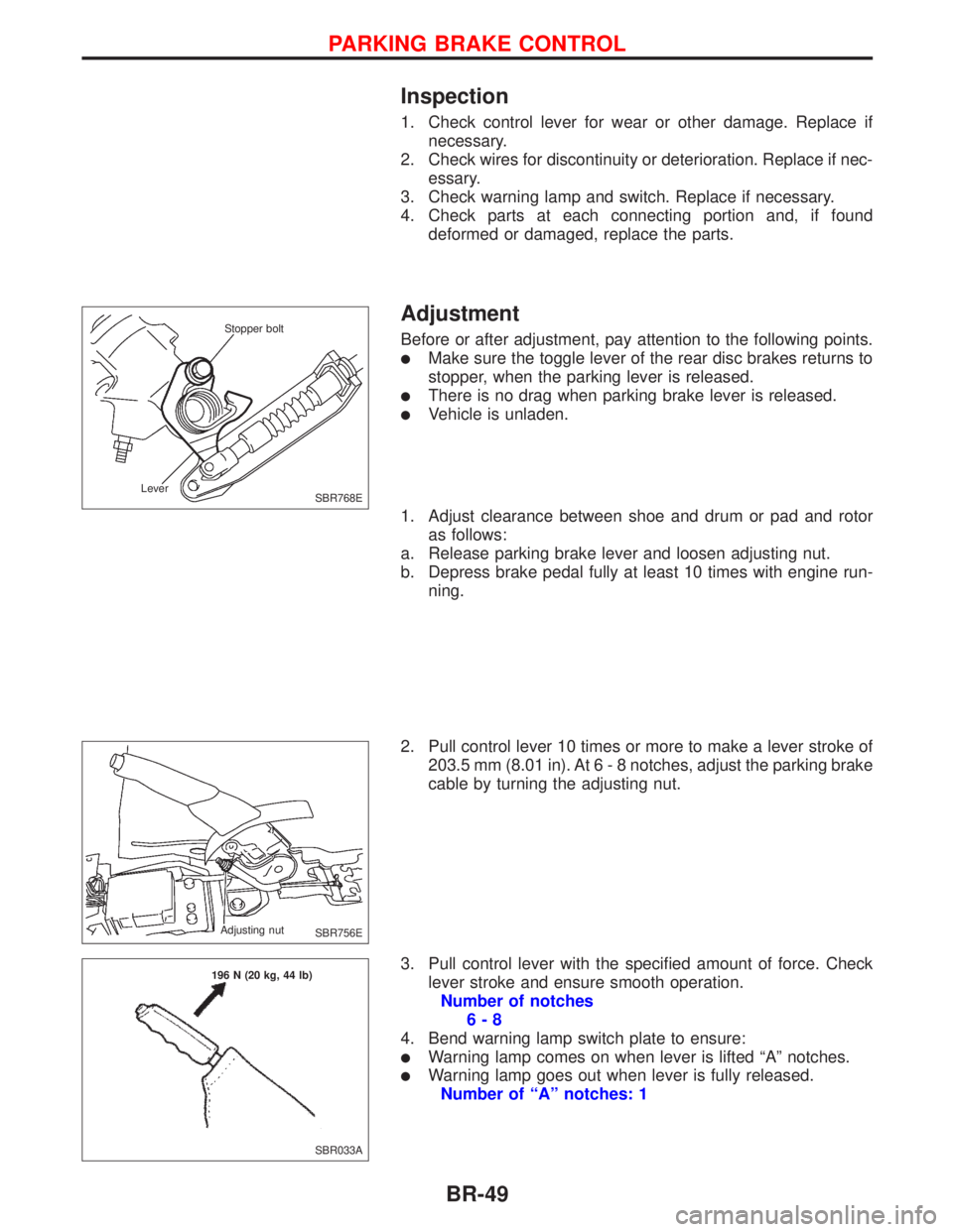
1. Adjust clearance between shoe and drum or pad and rotor
as follows:
a. Release parking brake lever and loosen adjusting nut.
b. Depress brake pedal fully at least 10 times with engine run-
ning.
2. Pull control lever 10 times or more to make a lever stroke of
203.5 mm (8.01 in). At6-8notches, adjust the parking brake
cable by turning the adjusting nut.
3. Pull control lever with the specified amount of force. Check
lever stroke and ensure smooth operation.
Number of notches
6-8
4. Bend warning lamp switch plate to ensure:
lWarning lamp comes on when lever is lifted ªAº notches.
lWarning lamp goes out when lever is fully released.
Number of ªAº notches: 1
SBR768E Stopper bolt
Lever
SBR756E Adjusting nut
SBR033A 196 N (20 kg, 44 lb)
PARKING BRAKE CONTROL
BR-49
Page 214 of 2267

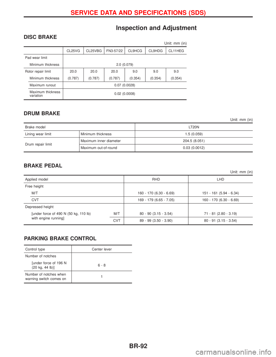
Inspection and Adjustment
DISC BRAKE
Unit: mm (in)
CL25VG CL25VBG FN3-57/22 CL9HCG CL9HDG CL11HEG
Pad wear limit
Minimum thickness 2.0 (0.079)
Rotor repair limit 20.0 20.0 20.0 9.0 9.0 9.0
Minimum thickness (0.787) (0.787) (0.787) (0.354) (0.354) (0.354)
Maximum runout 0.07 (0.0028)
Maximum thickness
variation0.02 (0.0008)
DRUM BRAKE
Unit: mm (in)
Brake modelLT20N
Lining wear limit Minimum thickness 1.5 (0.059)
Drum repair limitMaximum inner diameter 204.5 (8.051)
Maximum out-of-round 0.03 (0.0012)
BRAKE PEDAL
Unit: mm (in)
Applied model RHD LHD
Free height
M/T 160 - 170 (6.30 - 6.69) 151 - 161 (5.94 - 6.34)
CVT 169 - 179 (6.65 - 7.05) 160 - 170 (6.30 - 6.69)
Depressed height
[under force of 490 N (50 kg, 110 lb)
with engine running]M/T 80 - 90 (3.15 - 3.54) 71 - 81 (2.80 - 3.19)
CVT 89 - 99 (3.50 - 3.90) 80 - 91 (3.15 - 3.54)
PARKING BRAKE CONTROL
Control type Center lever
Number of notches
[under force of 196 N
(20 kg, 44 lb)]6-8
Number of notches when
warning switch comes on1
SERVICE DATA AND SPECIFICATIONS (SDS)
BR-92