1999 NISSAN PRIMERA ESP
[x] Cancel search: ESPPage 2 of 2267
FOREWORD
This manual contains maintenance and repair procedures for NISSAN
PRIMERA, model P11-144 series.
In order to assure your safety and the efficient functioning of the vehicle,
this manual should be read thoroughly. It is especially important that the
PRECAUTIONS in the GI section be completely understood before starting
any repair task.
All information in this manual is based on the latest product information
at the time of publication. The right is reserved to make changes in speci-
fications and methods at any time without notice.
IMPORTANT SAFETY NOTICE
The proper performance of service is essential for both the safety of the
technician and the efficient functioning of the vehicle.
The service methods in this Service Manual are described in such a man-
ner that the service may be performed safely and accurately.
Service varies with the procedures used, the skills of the technician and the
tools and parts available. Accordingly, anyone using service procedures,
tools or parts which are not specifically recommended by NISSAN must
first completely satisfy himself that neither his safety nor the vehicle's
safety will be jeopardized by the service method selected.
NISSAN EUROPE N.V.
Service Operations Section
Amsterdam, The Netherlands
Page 9 of 2267
The blinking of the CVT or SPORT indicator lamp for about 8 seconds will appear only once and be cleared.
The customer may resume normal driving conditions.
Always follow the ªWORK FLOWº (Refer to AT-32).
The SELF-DIAGNOSIS results will be as follows:
The first SELF-DIAGNOSIS will indicate damage to the vehicle speed sensor or the revolution sensor.
During the next SELF-DIAGNOSIS, performed after checking the sensor, no damages will be indicated.
OBD SELF-DIAGNOSISNCAT0004S04ICVT self-diagnosis is performed by the TCM in combination with the ECM. The results can be read through
the blinking pattern of the CVT or SPORT indicator. Refer to the table on AT-19 for the indicator used to
display each self-diagnostic result.
IThe self-diagnostic results indicated by the MI are automatically stored in both the ECM and TCM memo-
ries.
Always perform the procedure ªHOW TO ERASE DTCº on AT-16 to complete the repair and avoid
unnecessary blinking of the MI.
For details of OBD, refer to EC section (ªON BOARD DIAGNOSTIC SYSTEM DESCRIPTIONº).
ICertain systems and components, especially those related to OBD, may use a new style slide-
locking type harness connector.
For description and how to disconnect, refer to EL section, ªDescriptionº, ªHARNESS CONNEC-
TORº.
Wiring Diagrams and Trouble DiagnosisNCAT0005When you read wiring diagrams, refer to the followings:
IªHOW TO READ WIRING DIAGRAMSº in GI section
IªPOWER SUPPLY ROUTINGº for power distribution circuit in EL section
When you perform trouble diagnosis, refer to the followings:
IªHOW TO FOLLOW TEST GROUP IN TROUBLE DIAGNOSISº in GI section
IªHOW TO PERFORM EFFICIENT DIAGNOSIS FOR AN ELECTRICAL INCIDENTº in GI section
PRECAUTIONS
Service Notice or Precautions (Cont'd)
AT-7
Page 13 of 2267
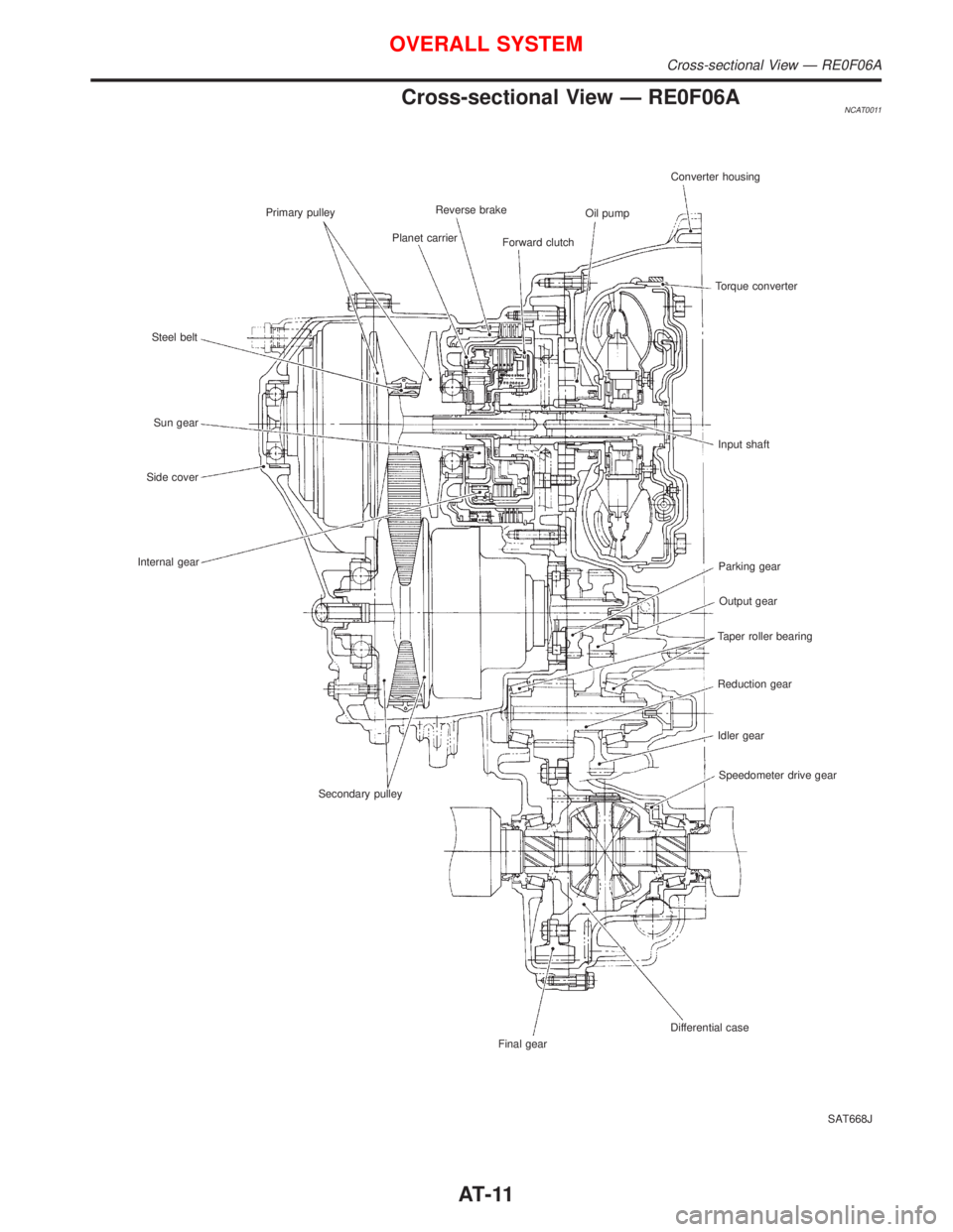
Cross-sectional View Ð RE0F06ANCAT0011
SAT668J Primary pulley
Steel belt
Sun gear
Side cover
Internal gear
Secondary pulley
Final gearDifferential caseSpeedometer drive gear Idler gear Reduction gear Taper roller bearingOutput gear Parking gear Input shaft Torque converter Converter housing
Oil pump
Forward clutch Reverse brake
Planet carrier
OVERALL SYSTEM
Cross-sectional View Ð RE0F06A
AT-11
Page 16 of 2267
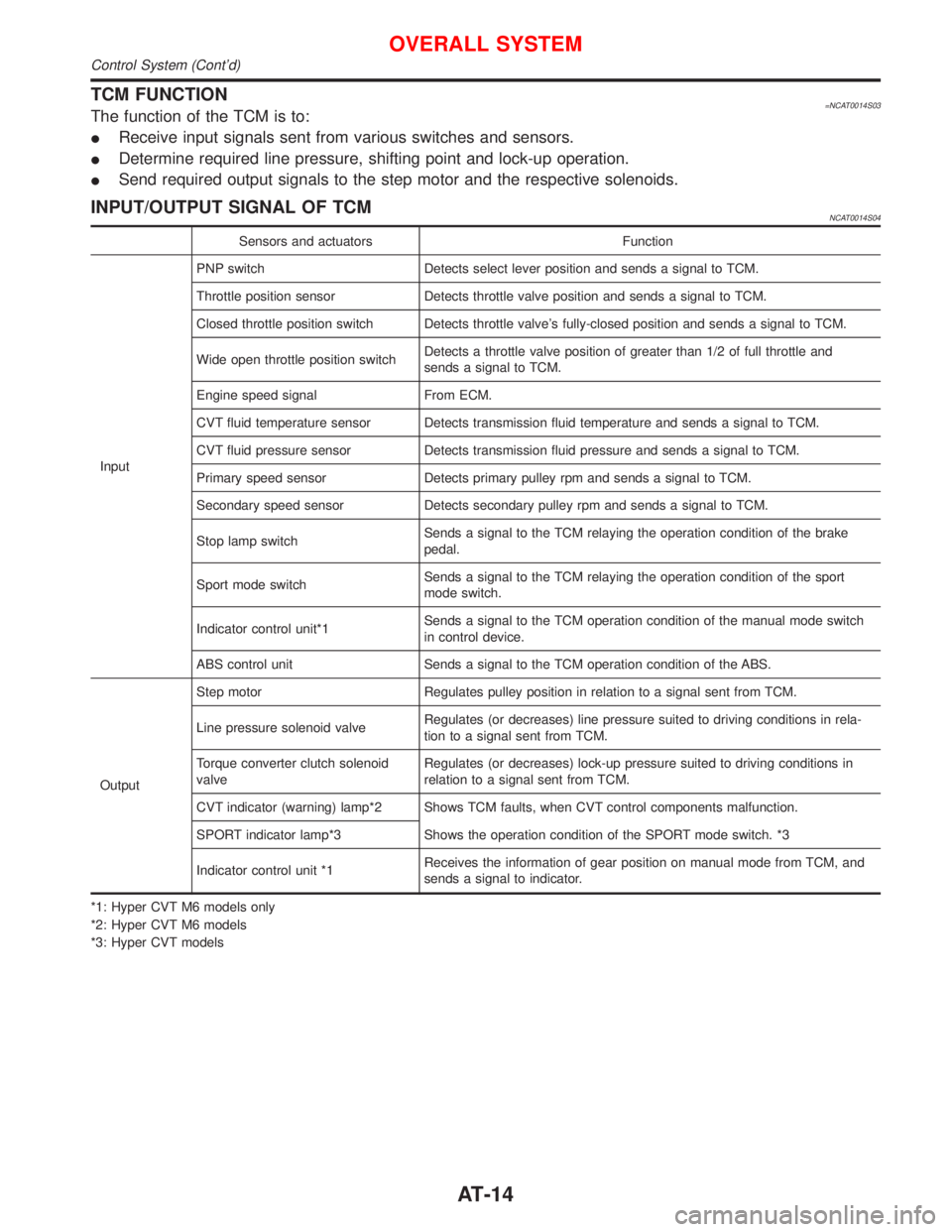
TCM FUNCTION=NCAT0014S03The function of the TCM is to:
IReceive input signals sent from various switches and sensors.
IDetermine required line pressure, shifting point and lock-up operation.
ISend required output signals to the step motor and the respective solenoids.
INPUT/OUTPUT SIGNAL OF TCMNCAT0014S04
Sensors and actuators Function
InputPNP switch Detects select lever position and sends a signal to TCM.
Throttle position sensor Detects throttle valve position and sends a signal to TCM.
Closed throttle position switch Detects throttle valve's fully-closed position and sends a signal to TCM.
Wide open throttle position switchDetects a throttle valve position of greater than 1/2 of full throttle and
sends a signal to TCM.
Engine speed signal From ECM.
CVT fluid temperature sensor Detects transmission fluid temperature and sends a signal to TCM.
CVT fluid pressure sensor Detects transmission fluid pressure and sends a signal to TCM.
Primary speed sensor Detects primary pulley rpm and sends a signal to TCM.
Secondary speed sensor Detects secondary pulley rpm and sends a signal to TCM.
Stop lamp switchSends a signal to the TCM relaying the operation condition of the brake
pedal.
Sport mode switchSends a signal to the TCM relaying the operation condition of the sport
mode switch.
Indicator control unit*1Sends a signal to the TCM operation condition of the manual mode switch
in control device.
ABS control unit Sends a signal to the TCM operation condition of the ABS.
OutputStep motor Regulates pulley position in relation to a signal sent from TCM.
Line pressure solenoid valveRegulates (or decreases) line pressure suited to driving conditions in rela-
tion to a signal sent from TCM.
Torque converter clutch solenoid
valveRegulates (or decreases) lock-up pressure suited to driving conditions in
relation to a signal sent from TCM.
CVT indicator (warning) lamp*2 Shows TCM faults, when CVT control components malfunction.
SPORT indicator lamp*3 Shows the operation condition of the SPORT mode switch. *3
Indicator control unit *1Receives the information of gear position on manual mode from TCM, and
sends a signal to indicator.
*1: Hyper CVT M6 models only
*2: Hyper CVT M6 models
*3: Hyper CVT models
OVERALL SYSTEM
Control System (Cont'd)
AT-14
Page 17 of 2267
IntroductionNCAT0017The CVT system has two self-diagnostic systems.
The first is the emission-related on board diagnostic system (OBD) performed by the TCM in combination with
the ECM. The malfunction is indicated by the MI (malfunction indicator) and is stored as a DTC in the ECM
memory but not the TCM memory.
The second is the TCM original self-diagnosis indicated by the CVT indicator (warning) lamp or SPORT indi-
cator lamp. The malfunction is stored in the TCM memory. The detected items are overlapped with OBD self-
diagnostic items. For detail, refer to AT-26.
OBD Function for CVT SystemNCAT0018The ECM provides emission-related on board diagnostic (OBD) functions for the CVT system. One function
is to receive a signal from the TCM used with OBD-related parts of the CVT system. The signal is sent to the
ECM when a malfunction occurs in the corresponding OBD-related part. The other function is to indicate a
diagnostic result by means of the MI (malfunction indicator) on the instrument panel. Sensors, switches and
solenoid valves are used as sensing elements.
The MI automatically illuminates in Two Trip Detection Logic when a malfunction is sensed in relation to CVT
system parts.
OBD Diagnostic Trouble Code (DTC)NCAT0020HOW TO READ DTC AND 1ST TRIP DTCNCAT0020S01DTC and 1st trip DTC can be read by the following methods.
1.(
No Tools)The number of blinks of the malfunction indicator in the Diagnostic Test Mode II (Self-Di-
agnostic Results) Examples: 0705, 0710, 0715, 0720, etc. For details, refer to EC section [ªMalfunction
Indicator (MI)º, ªON BOARD DIAGNOSTIC SYSTEM DESCRIPTIONº].
These DTCs are controlled by NISSAN.
2.(
with CONSULT-II orGST)CONSULT-II or GST (Generic Scan Tool) Examples: P0705, P0710,
P0720, P0725, etc.
These DTCs are prescribed by ISO15031-6.
(CONSULT-II also displays the malfunctioning component or system.)
I1st trip DTC No. is the same as DTC No.
IOutput of the diagnostic trouble code indicates that the indicated circuit has a malfunction.
However, in case of the Mode II and GST they do not indicate whether the malfunction is still
occurring or occurred in the past and returned to normal.
CONSULT-II can identify them as shown below. Therefore, using CONSULT-II (if available) is rec-
ommended.
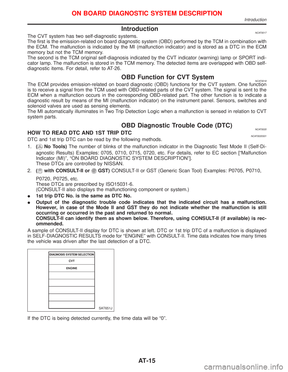
A sample of CONSULT-II display for DTC is shown at left. DTC or 1st trip DTC of a malfunction is displayed
in SELF-DIAGNOSTIC RESULTS mode for ªENGINEº with CONSULT-II. Time data indicates how many times
the vehicle was driven after the last detection of a DTC.
If the DTC is being detected currently, the time data will be ª0º.
SAT651J
ON BOARD DIAGNOSTIC SYSTEM DESCRIPTION
Introduction
AT-15
Page 31 of 2267
IntroductionNCAT0023
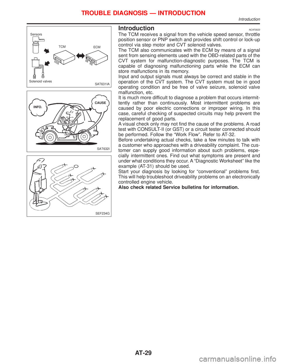
The TCM receives a signal from the vehicle speed sensor, throttle
position sensor or PNP switch and provides shift control or lock-up
control via step motor and CVT solenoid valves.
The TCM also communicates with the ECM by means of a signal
sent from sensing elements used with the OBD-related parts of the
CVT system for malfunction-diagnostic purposes. The TCM is
capable of diagnosing malfunctioning parts while the ECM can
store malfunctions in its memory.
Input and output signals must always be correct and stable in the
operation of the CVT system. The CVT system must be in good
operating condition and be free of valve seizure, solenoid valve
malfunction, etc.
It is much more difficult to diagnose a problem that occurs intermit-
tently rather than continuously. Most intermittent problems are
caused by poor electric connections or improper wiring. In this
case, careful checking of suspected circuits may help prevent the
replacement of good parts.
A visual check only may not find the cause of the problems. A road
test with CONSULT-II (or GST) or a circuit tester connected should
be performed. Follow the ªWork Flowº. Refer to AT-32.
Before undertaking actual checks, take a few minutes to talk with
a customer who approaches with a driveability complaint. The cus-
tomer can supply good information about such problems, espe-
cially intermittent ones. Find out what symptoms are present and
under what conditions they occur. A ªDiagnostic Worksheetº like the
example (AT-31) should be used.
Start your diagnosis by looking for ªconventionalº problems first.
This will help troubleshoot driveability problems on an electronically
controlled engine vehicle.
Also check related Service bulletins for information.
SAT631IA Sensors
TCM
ECM
Solenoid valves
SAT632I INFO.CAUSE
SEF234G
TROUBLE DIAGNOSIS Ð INTRODUCTION
Introduction
AT-29
Page 35 of 2267
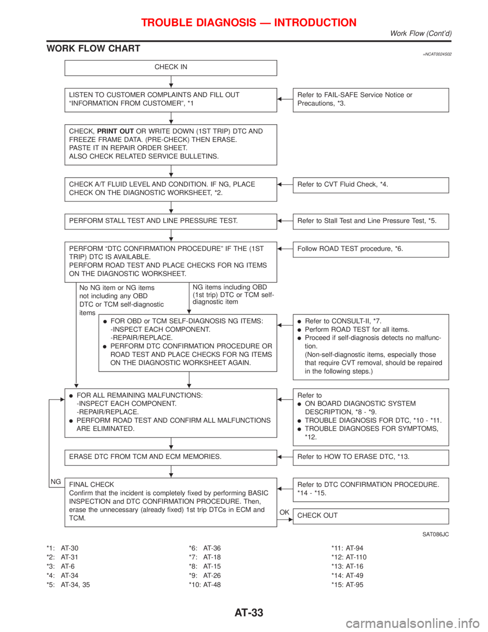
WORK FLOW CHART=NCAT0024S02
CHECK IN
LISTEN TO CUSTOMER COMPLAINTS AND FILL OUT
ªINFORMATION FROM CUSTOMERº, *1FRefer to FAIL-SAFE Service Notice or
Precautions, *3.
CHECK,PRINT OUTOR WRITE DOWN (1ST TRIP) DTC AND
FREEZE FRAME DATA. (PRE-CHECK) THEN ERASE.
PASTE IT IN REPAIR ORDER SHEET.
ALSO CHECK RELATED SERVICE BULLETINS.
CHECK A/T FLUID LEVEL AND CONDITION. IF NG, PLACE
CHECK ON THE DIAGNOSTIC WORKSHEET, *2.FRefer to CVT Fluid Check, *4.
PERFORM STALL TEST AND LINE PRESSURE TEST.FRefer to Stall Test and Line Pressure Test, *5.
PERFORM ªDTC CONFIRMATION PROCEDUREº IF THE (1ST
TRIP) DTC IS AVAILABLE.
PERFORM ROAD TEST AND PLACE CHECKS FOR NG ITEMS
ON THE DIAGNOSTIC WORKSHEET.
H
No NG item or NG items
not including any OBD
DTC or TCM self-diagnostic
itemsNG items including OBD
(1st trip) DTC or TCM self-
diagnostic item
FFollow ROAD TEST procedure, *6.
lFOR OBD or TCM SELF-DIAGNOSIS NG ITEMS:
-INSPECT EACH COMPONENT.
-REPAIR/REPLACE.
lPERFORM DTC CONFIRMATION PROCEDURE OR
ROAD TEST AND PLACE CHECKS FOR NG ITEMS
ON THE DIAGNOSTIC WORKSHEET AGAIN.
FlRefer to CONSULT-II, *7.
lPerform ROAD TEST for all items.
lProceed if self-diagnosis detects no malfunc-
tion.
(Non-self-diagnostic items, especially those
that require CVT removal, should be repaired
in the following steps.)
ElFOR ALL REMAINING MALFUNCTIONS:
-INSPECT EACH COMPONENT.
-REPAIR/REPLACE.
lPERFORM ROAD TEST AND CONFIRM ALL MALFUNCTIONS
ARE ELIMINATED.
FRefer to
lON BOARD DIAGNOSTIC SYSTEM
DESCRIPTION, *8 - *9.
lTROUBLE DIAGNOSIS FOR DTC, *10 - *11.
lTROUBLE DIAGNOSES FOR SYMPTOMS,
*12.
ERASE DTC FROM TCM AND ECM MEMORIES.FRefer to HOW TO ERASE DTC, *13.
NGFINAL CHECK
Confirm that the incident is completely fixed by performing BASIC
INSPECTION and DTC CONFIRMATION PROCEDURE. Then,
erase the unnecessary (already fixed) 1st trip DTCs in ECM and
TCM.FRefer to DTC CONFIRMATION PROCEDURE.
*14 - *15.
EOK
CHECK OUT
SAT086JC
*1: AT-30
*2: AT-31
*3: AT-6
*4: AT-34
*5: AT-34, 35*6: AT-36
*7: AT-18
*8: AT-15
*9: AT-26
*10: AT-48*11: AT-94
*12: AT-110
*13: AT-16
*14: AT-49
*15: AT-95
TROUBLE DIAGNOSIS Ð INTRODUCTION
Work Flow (Cont'd)
H
H
H
H
H
H
H
H
H
AT-33
Page 38 of 2267
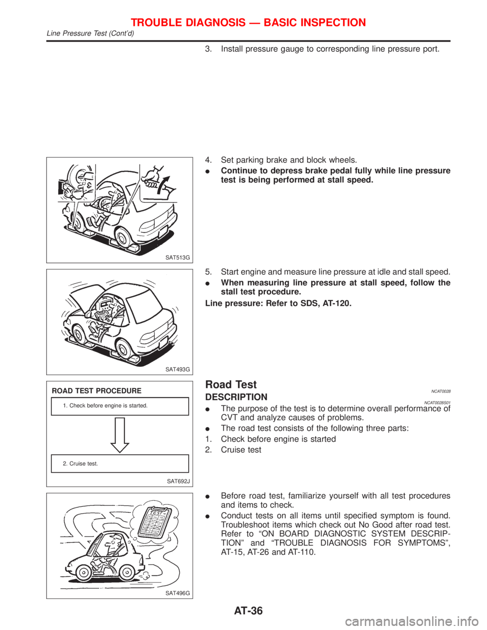
3. Install pressure gauge to corresponding line pressure port.
4. Set parking brake and block wheels.
IContinue to depress brake pedal fully while line pressure
test is being performed at stall speed.
5. Start engine and measure line pressure at idle and stall speed.
IWhen measuring line pressure at stall speed, follow the
stall test procedure.
Line pressure: Refer to SDS, AT-120.
Road TestNCAT0028DESCRIPTIONNCAT0028S01IThe purpose of the test is to determine overall performance of
CVT and analyze causes of problems.
IThe road test consists of the following three parts:
1. Check before engine is started
2. Cruise test
IBefore road test, familiarize yourself with all test procedures
and items to check.
IConduct tests on all items until specified symptom is found.
Troubleshoot items which check out No Good after road test.
Refer to ªON BOARD DIAGNOSTIC SYSTEM DESCRIP-
TIONº and ªTROUBLE DIAGNOSIS FOR SYMPTOMSº,
AT-15, AT-26 and AT-110.
SAT513G
SAT493G
SAT692J
ROAD TEST PROCEDURE
1. Check before engine is started.
2. Cruise test.
SAT496G
TROUBLE DIAGNOSIS Ð BASIC INSPECTION
Line Pressure Test (Cont'd)
AT-36