1999 NISSAN PRIMERA ESP
[x] Cancel search: ESPPage 444 of 2267
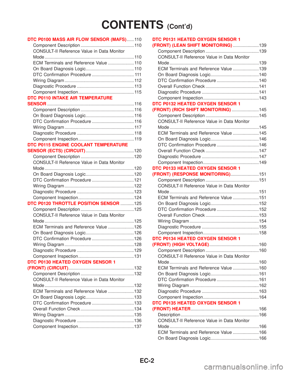
DTC P0100 MASS AIR FLOW SENSOR (MAFS)...... 110
Component Description ........................................... 110
CONSULT-II Reference Value in Data Monitor
Mode ........................................................................ 110
ECM Terminals and Reference Value ..................... 110
On Board Diagnosis Logic....................................... 110
DTC Confirmation Procedure .................................. 111
Wiring Diagram ........................................................ 112
Diagnostic Procedure .............................................. 113
Component Inspection ............................................. 115
DTC P0110 INTAKE AIR TEMPERATURE
SENSOR...................................................................... 116
Component Description ........................................... 116
On Board Diagnosis Logic....................................... 116
DTC Confirmation Procedure .................................. 116
Wiring Diagram ........................................................ 117
Diagnostic Procedure .............................................. 118
Component Inspection ............................................. 119
DTC P0115 ENGINE COOLANT TEMPERATURE
SENSOR (ECTS) (CIRCUIT).......................................120
Component Description ...........................................120
CONSULT-II Reference Value in Data Monitor
Mode ........................................................................120
On Board Diagnosis Logic.......................................120
DTC Confirmation Procedure ..................................121
Wiring Diagram ........................................................122
Diagnostic Procedure ..............................................123
Component Inspection .............................................124
DTC P0120 THROTTLE POSITION SENSOR...........125
Component Description ...........................................125
CONSULT-II Reference Value in Data Monitor
Mode ........................................................................125
ECM Terminals and Reference Value .....................126
On Board Diagnosis Logic.......................................126
DTC Confirmation Procedure ..................................126
Wiring Diagram ........................................................128
Diagnostic Procedure ..............................................129
Component Inspection .............................................131
DTC P0130 HEATED OXYGEN SENSOR 1
(FRONT) (CIRCUIT).....................................................132
Component Description ...........................................132
CONSULT-II Reference Value in Data Monitor
Mode ........................................................................132
ECM Terminals and Reference Value .....................132
On Board Diagnosis Logic.......................................133
DTC Confirmation Procedure ..................................133
Overall Function Check ...........................................134
Wiring Diagram ........................................................135
Diagnostic Procedure ..............................................136
Component Inspection .............................................137DTC P0131 HEATED OXYGEN SENSOR 1
(FRONT) (LEAN SHIFT MONITORING).....................139
Component Description ...........................................139
CONSULT-II Reference Value in Data Monitor
Mode ........................................................................139
ECM Terminals and Reference Value .....................139
On Board Diagnosis Logic.......................................140
DTC Confirmation Procedure ..................................140
Overall Function Check ...........................................141
Diagnostic Procedure ..............................................141
Component Inspection .............................................143
DTC P0132 HEATED OXYGEN SENSOR 1
(FRONT) (RICH SHIFT MONITORING)......................145
Component Description ...........................................145
CONSULT-II Reference Value in Data Monitor
Mode ........................................................................145
ECM Terminals and Reference Value .....................145
On Board Diagnosis Logic.......................................146
DTC Confirmation Procedure ..................................146
Overall Function Check ...........................................147
Diagnostic Procedure ..............................................147
Component Inspection .............................................149
DTC P0133 HEATED OXYGEN SENSOR 1
(FRONT) (RESPONSE MONITORING).......................151
Component Description ...........................................151
CONSULT-II Reference Value in Data Monitor
Mode ........................................................................151
ECM Terminals and Reference Value .....................151
On Board Diagnosis Logic.......................................152
DTC Confirmation Procedure ..................................152
Overall Function Check ...........................................153
Wiring Diagram ........................................................154
Diagnostic Procedure ..............................................155
Component Inspection .............................................158
DTC P0134 HEATED OXYGEN SENSOR 1
(FRONT) (HIGH VOLTAGE)........................................160
Component Description ...........................................160
CONSULT-II Reference Value in Data Monitor
Mode ........................................................................160
ECM Terminals and Reference Value .....................160
On Board Diagnosis Logic.......................................161
DTC Confirmation Procedure ..................................161
Wiring Diagram ........................................................162
Diagnostic Procedure ..............................................163
Component Inspection .............................................164
DTC P0135 HEATED OXYGEN SENSOR 1
(FRONT) HEATER.......................................................166
Description ...............................................................166
CONSULT-II Reference Value in Data Monitor
Mode ........................................................................166
ECM Terminals and Reference Value .....................166
On Board Diagnosis Logic.......................................166
CONTENTS(Cont'd)
EC-2
Page 445 of 2267
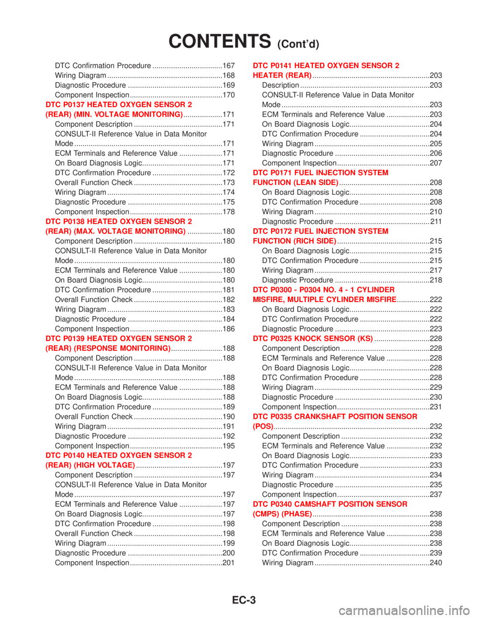
DTC Confirmation Procedure ..................................167
Wiring Diagram ........................................................168
Diagnostic Procedure ..............................................169
Component Inspection .............................................170
DTC P0137 HEATED OXYGEN SENSOR 2
(REAR) (MIN. VOLTAGE MONITORING)...................171
Component Description ...........................................171
CONSULT-II Reference Value in Data Monitor
Mode ........................................................................171
ECM Terminals and Reference Value .....................171
On Board Diagnosis Logic.......................................171
DTC Confirmation Procedure ..................................172
Overall Function Check ...........................................173
Wiring Diagram ........................................................174
Diagnostic Procedure ..............................................175
Component Inspection .............................................178
DTC P0138 HEATED OXYGEN SENSOR 2
(REAR) (MAX. VOLTAGE MONITORING).................180
Component Description ...........................................180
CONSULT-II Reference Value in Data Monitor
Mode ........................................................................180
ECM Terminals and Reference Value .....................180
On Board Diagnosis Logic.......................................180
DTC Confirmation Procedure ..................................181
Overall Function Check ...........................................182
Wiring Diagram ........................................................183
Diagnostic Procedure ..............................................184
Component Inspection .............................................186
DTC P0139 HEATED OXYGEN SENSOR 2
(REAR) (RESPONSE MONITORING).........................188
Component Description ...........................................188
CONSULT-II Reference Value in Data Monitor
Mode ........................................................................188
ECM Terminals and Reference Value .....................188
On Board Diagnosis Logic.......................................188
DTC Confirmation Procedure ..................................189
Overall Function Check ...........................................190
Wiring Diagram ........................................................191
Diagnostic Procedure ..............................................192
Component Inspection .............................................195
DTC P0140 HEATED OXYGEN SENSOR 2
(REAR) (HIGH VOLTAGE)..........................................197
Component Description ...........................................197
CONSULT-II Reference Value in Data Monitor
Mode ........................................................................197
ECM Terminals and Reference Value .....................197
On Board Diagnosis Logic.......................................197
DTC Confirmation Procedure ..................................198
Overall Function Check ...........................................198
Wiring Diagram ........................................................199
Diagnostic Procedure ..............................................200
Component Inspection .............................................201DTC P0141 HEATED OXYGEN SENSOR 2
HEATER (REAR).........................................................203
Description ...............................................................203
CONSULT-II Reference Value in Data Monitor
Mode ........................................................................203
ECM Terminals and Reference Value .....................203
On Board Diagnosis Logic.......................................204
DTC Confirmation Procedure ..................................204
Wiring Diagram ........................................................205
Diagnostic Procedure ..............................................206
Component Inspection .............................................207
DTC P0171 FUEL INJECTION SYSTEM
FUNCTION (LEAN SIDE)............................................208
On Board Diagnosis Logic.......................................208
DTC Confirmation Procedure ..................................208
Wiring Diagram ........................................................210
Diagnostic Procedure .............................................. 211
DTC P0172 FUEL INJECTION SYSTEM
FUNCTION (RICH SIDE).............................................215
On Board Diagnosis Logic.......................................215
DTC Confirmation Procedure ..................................215
Wiring Diagram ........................................................217
Diagnostic Procedure ..............................................218
DTC P0300 - P0304 NO.4-1CYLINDER
MISFIRE, MULTIPLE CYLINDER MISFIRE................222
On Board Diagnosis Logic.......................................222
DTC Confirmation Procedure ..................................222
Diagnostic Procedure ..............................................223
DTC P0325 KNOCK SENSOR (KS)...........................228
Component Description ...........................................228
ECM Terminals and Reference Value .....................228
On Board Diagnosis Logic.......................................228
DTC Confirmation Procedure ..................................228
Wiring Diagram ........................................................229
Diagnostic Procedure ..............................................230
Component Inspection .............................................231
DTC P0335 CRANKSHAFT POSITION SENSOR
(POS)............................................................................232
Component Description ...........................................232
ECM Terminals and Reference Value .....................232
On Board Diagnosis Logic.......................................233
DTC Confirmation Procedure ..................................233
Wiring Diagram ........................................................234
Diagnostic Procedure ..............................................235
Component Inspection .............................................237
DTC P0340 CAMSHAFT POSITION SENSOR
(CMPS) (PHASE).........................................................238
Component Description ...........................................238
ECM Terminals and Reference Value .....................238
On Board Diagnosis Logic.......................................238
DTC Confirmation Procedure ..................................239
Wiring Diagram ........................................................240
CONTENTS(Cont'd)
EC-3
Page 451 of 2267
Supplemental Restraint System (SRS) ªAIR
BAGº and ªSEAT BELT PRE-TENSIONERº
NCEC0002The Supplemental Restraint System ªAIR BAGº and ªSEAT BELT PRE-TENSIONERº, used along with a seat
belt, help to reduce the risk or severity of injury to the driver and front passenger in a frontal collision. The
Supplemental Restraint System consists of air bag modules (located in the center of the steering wheel and
on the instrument panel on the passenger side), seat belt pre-tensioners, a diagnosis sensor unit, warning
lamp, wiring harness and spiral cable.
In addition to the supplemental air bag modules for a frontal collision, the supplemental side air bag used along
with the seat belt helps to reduce the risk or severity of injury to the driver and front passenger in a side col-
lision. The supplemental side air bag consists of air bag modules (located in the outer side of front seats),
satellite sensor, diagnosis sensor unit (one of components of supplemental air bags for a frontal collision),
wiring harness, warning lamp (one of components of supplemental air bags for a frontal collision). Information
necessary to service the system safely is included in theRS sectionof this Service Manual.
WARNING:
ITo avoid rendering the SRS inoperative, which could increase the risk of personal injury or death
in the event of a collision which would result in air bag inflation, all maintenance must be performed
by an authorized NISSAN dealer.
IImproper maintenance, including incorrect removal and installation of the SRS, can lead to per-
sonal injury caused by unintentional activation of the system.
IDo not use electrical test equipment on any circuit related to the SRS unless instructed to in this
Service Manual. SRS wiring harnesses (except ªSEAT BELT PRE-TENSIONERº connector) can be
identified with yellow harness connector (and with yellow harness protector or yellow insulation
tape before the harness connectors).
Precautions for On Board Diagnostic (OBD)
System of Engine
NCEC0003The ECM has an on board diagnostic system. It will light up the malfunction indicator (MI) to warn the driver
of a malfunction causing emission deterioration.
CAUTION:
IBe sure to turn the ignition switch ªOFFº and disconnect the negative battery terminal before any
repair or inspection work. The open/short circuit of related switches, sensors, solenoid valves, etc.
will cause the MI to light up.
IBe sure to connect and lock the connectors securely after work. A loose (unlocked) connector will
cause the MI to light up due to the open circuit. (Be sure the connector is free from water, grease,
dirt, bent terminals, etc.)
ICertain systems and components, especially those related to OBD, may use a new style slide-
locking type harness connector.
For description and how to disconnect, refer to EL section, ªDescriptionº, ªHARNESS CONNEC-
TORº.
IBe sure to route and secure the harnesses properly after work. The interference of the harness with
a bracket, etc. may cause the MI to light up due to the short circuit.
IBe sure to connect rubber tubes properly after work. A misconnected or disconnected rubber tube
may cause the MI to light up due to the malfunction of the EGR system or fuel injection system,
etc.
IBe sure to erase the unnecessary malfunction information (repairs completed) from the ECM before
returning the vehicle to the customer.
PRECAUTIONSQG16I18DE
Supplemental Restraint System (SRS) ªAIR BAGº and ªSEAT BELT PRE-TENSIONERº
EC-9
Page 480 of 2267
FREEZE FRAME DATA AND 1ST TRIP FREEZE FRAME DATANCEC0031S02The ECM records the driving conditions such as fuel system status, calculated load value, engine coolant
temperature, short term fuel trim, long term fuel trim, engine speed, vehicle speed and absolute pressure
sensor at the moment a malfunction is detected.
Data which are stored in the ECM memory, along with the 1st trip DTC, are called 1st trip freeze frame data.
The data, stored together with the DTC data, are called freeze frame data and displayed on CONSULT-II or
GST. The 1st trip freeze frame data can only be displayed on the CONSULT-II screen, not on the GST. For
details, see EC-QG-58.
Only one set of freeze frame data (either 1st trip freeze frame data or freeze frame data) can be stored in the
ECM. 1st trip freeze frame data is stored in the ECM memory along with the 1st trip DTC. There is no prior-
ity for 1st trip freeze frame data and it is updated each time a different 1st trip DTC is detected. However, once
freeze frame data (2nd trip detection/MI on) is stored in the ECM memory, 1st trip freeze frame data is no
longer stored. Remember, only one set of freeze frame data can be stored in the ECM. The ECM has the fol-
lowing priorities to update the data.
Priority Items
1Freeze frame data Misfire Ð DTC: P0300 - P0304 (0300 - 0304)
Fuel Injection System Function Ð DTC: P0171 (0171), P0172 (0172)
2 Except the above items
3 1st trip freeze frame data
For example, the EGR malfunction (Priority: 2) was detected and the freeze frame data was stored in the 2nd
trip. After that when the misfire (Priority: 1) is detected in another trip, the freeze frame data will be updated
from the EGR malfunction to the misfire. The 1st trip freeze frame data is updated each time a different mal-
function is detected. There is no priority for 1st trip freeze frame data. However, once freeze frame data is
stored in the ECM memory, 1st trip freeze data is no longer stored (because only one freeze frame data or
1st trip freeze frame data can be stored in the ECM). If freeze frame data is stored in the ECM memory and
freeze frame data with the same priority occurs later, the first (original) freeze frame data remains unchanged
in the ECM memory.
Both 1st trip freeze frame data and freeze frame data (along with the DTCs) are cleared when the ECM
memory is erased. Procedures for clearing the ECM memory are described in ªHOW TO ERASE EMISSION-
RELATED DIAGNOSTIC INFORMATIONº. Refer to EC-QG-44.
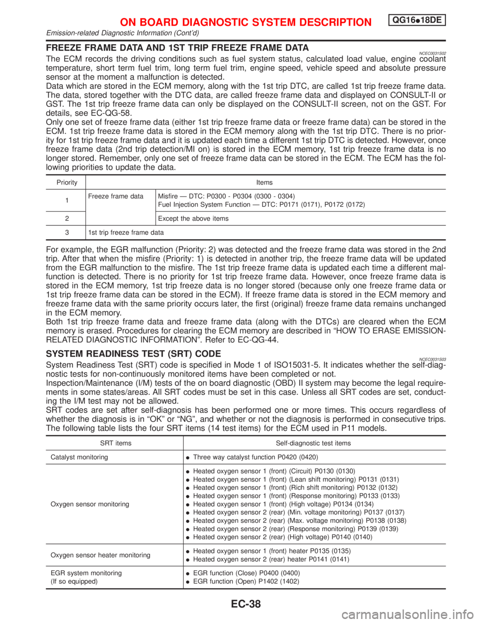
SYSTEM READINESS TEST (SRT) CODENCEC0031S03System Readiness Test (SRT) code is specified in Mode 1 of ISO15031-5. It indicates whether the self-diag-
nostic tests for non-continuously monitored items have been completed or not.
Inspection/Maintenance (I/M) tests of the on board diagnostic (OBD) II system may become the legal require-
ments in some states/areas. All SRT codes must be set in this case. Unless all SRT codes are set, conduct-
ing the I/M test may not be allowed.
SRT codes are set after self-diagnosis has been performed one or more times. This occurs regardless of
whether the diagnosis is in ªOKº or ªNGº, and whether or not the diagnosis is performed in consecutive trips.
The following table lists the four SRT items (14 test items) for the ECM used in P11 models.
SRT items Self-diagnostic test items
Catalyst monitoringIThree way catalyst function P0420 (0420)
Oxygen sensor monitoringIHeated oxygen sensor 1 (front) (Circuit) P0130 (0130)
IHeated oxygen sensor 1 (front) (Lean shift monitoring) P0131 (0131)
IHeated oxygen sensor 1 (front) (Rich shift monitoring) P0132 (0132)
IHeated oxygen sensor 1 (front) (Response monitoring) P0133 (0133)
IHeated oxygen sensor 1 (front) (High voltage) P0134 (0134)
IHeated oxygen sensor 2 (rear) (Min. voltage monitoring) P0137 (0137)
IHeated oxygen sensor 2 (rear) (Max. voltage monitoring) P0138 (0138)
IHeated oxygen sensor 2 (rear) (Response monitoring) P0139 (0139)
IHeated oxygen sensor 2 (rear) (High voltage) P0140 (0140)
Oxygen sensor heater monitoringIHeated oxygen sensor 1 (front) heater P0135 (0135)
IHeated oxygen sensor 2 (rear) heater P0141 (0141)
EGR system monitoring
(If so equipped)IEGR function (Close) P0400 (0400)
IEGR function (Open) P1402 (1402)
ON BOARD DIAGNOSTIC SYSTEM DESCRIPTIONQG16I18DE
Emission-related Diagnostic Information (Cont'd)
EC-38
Page 505 of 2267
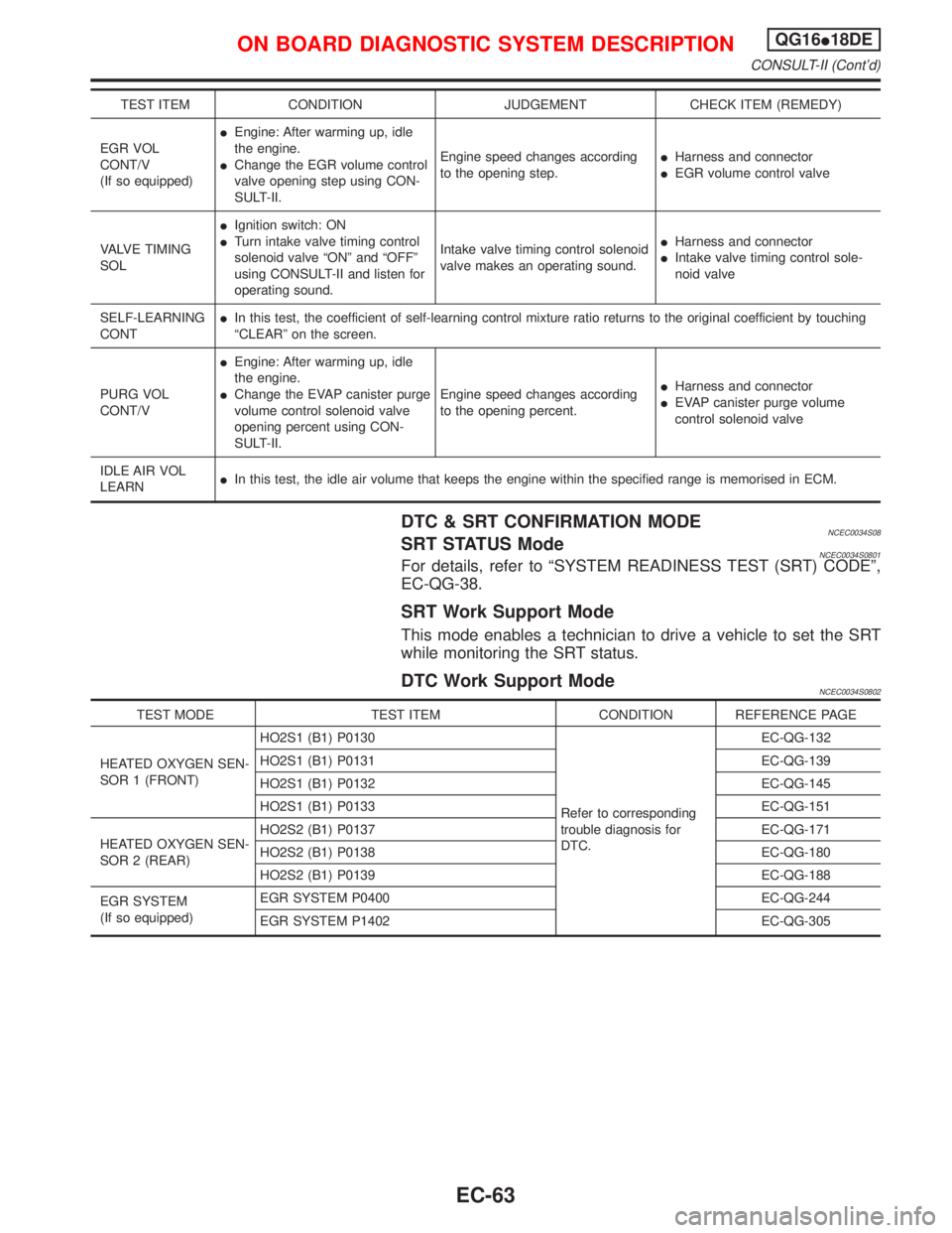
TEST ITEM CONDITION JUDGEMENT CHECK ITEM (REMEDY)
EGR VOL
CONT/V
(If so equipped)IEngine: After warming up, idle
the engine.
IChange the EGR volume control
valve opening step using CON-
SULT-II.Engine speed changes according
to the opening step.IHarness and connector
IEGR volume control valve
VALVE TIMING
SOLIIgnition switch: ON
ITurn intake valve timing control
solenoid valve ªONº and ªOFFº
using CONSULT-II and listen for
operating sound.Intake valve timing control solenoid
valve makes an operating sound.IHarness and connector
IIntake valve timing control sole-
noid valve
SELF-LEARNING
CONTIIn this test, the coefficient of self-learning control mixture ratio returns to the original coefficient by touching
ªCLEARº on the screen.
PURG VOL
CONT/VIEngine: After warming up, idle
the engine.
IChange the EVAP canister purge
volume control solenoid valve
opening percent using CON-
SULT-II.Engine speed changes according
to the opening percent.IHarness and connector
IEVAP canister purge volume
control solenoid valve
IDLE AIR VOL
LEARNIIn this test, the idle air volume that keeps the engine within the specified range is memorised in ECM.
DTC & SRT CONFIRMATION MODENCEC0034S08SRT STATUS ModeNCEC0034S0801For details, refer to ªSYSTEM READINESS TEST (SRT) CODEº,
EC-QG-38.
SRT Work Support Mode
This mode enables a technician to drive a vehicle to set the SRT
while monitoring the SRT status.
DTC Work Support ModeNCEC0034S0802
TEST MODE TEST ITEM CONDITION REFERENCE PAGE
HEATED OXYGEN SEN-
SOR 1 (FRONT)HO2S1 (B1) P0130
Refer to corresponding
trouble diagnosis for
DTC.EC-QG-132
HO2S1 (B1) P0131 EC-QG-139
HO2S1 (B1) P0132 EC-QG-145
HO2S1 (B1) P0133 EC-QG-151
HEATED OXYGEN SEN-
SOR 2 (REAR)HO2S2 (B1) P0137 EC-QG-171
HO2S2 (B1) P0138 EC-QG-180
HO2S2 (B1) P0139 EC-QG-188
EGR SYSTEM
(If so equipped)EGR SYSTEM P0400 EC-QG-244
EGR SYSTEM P1402 EC-QG-305
ON BOARD DIAGNOSTIC SYSTEM DESCRIPTIONQG16I18DE
CONSULT-II (Cont'd)
EC-63
Page 506 of 2267
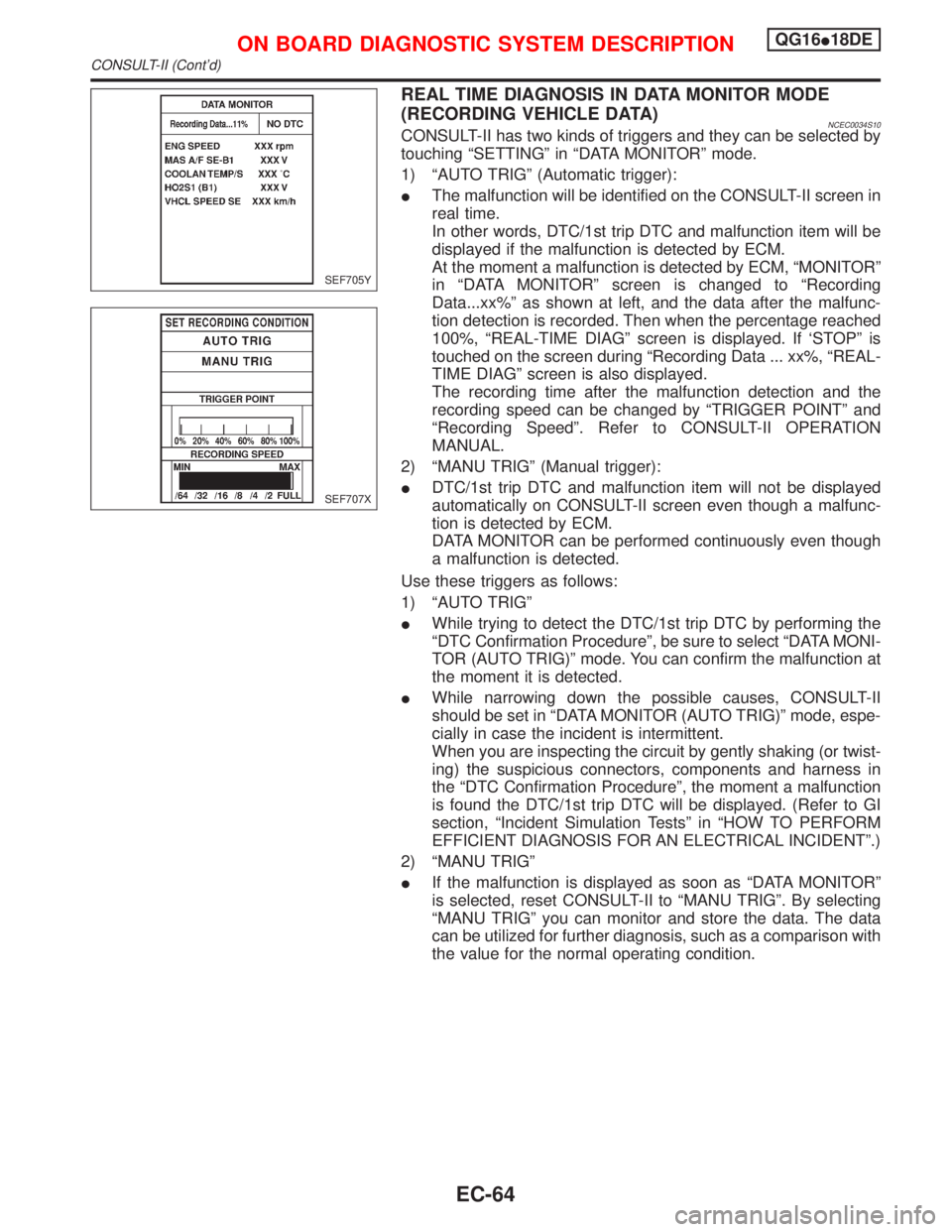
REAL TIME DIAGNOSIS IN DATA MONITOR MODE
(RECORDING VEHICLE DATA)
NCEC0034S10CONSULT-II has two kinds of triggers and they can be selected by
touching ªSETTINGº in ªDATA MONITORº mode.
1) ªAUTO TRIGº (Automatic trigger):
IThe malfunction will be identified on the CONSULT-II screen in
real time.
In other words, DTC/1st trip DTC and malfunction item will be
displayed if the malfunction is detected by ECM.
At the moment a malfunction is detected by ECM, ªMONITORº
in ªDATA MONITORº screen is changed to ªRecording
Data...xx%º as shown at left, and the data after the malfunc-
tion detection is recorded. Then when the percentage reached
100%, ªREAL-TIME DIAGº screen is displayed. If `STOPº is
touched on the screen during ªRecording Data ... xx%, ªREAL-
TIME DIAGº screen is also displayed.
The recording time after the malfunction detection and the
recording speed can be changed by ªTRIGGER POINTº and
ªRecording Speedº. Refer to CONSULT-II OPERATION
MANUAL.
2) ªMANU TRIGº (Manual trigger):
IDTC/1st trip DTC and malfunction item will not be displayed
automatically on CONSULT-II screen even though a malfunc-
tion is detected by ECM.
DATA MONITOR can be performed continuously even though
a malfunction is detected.
Use these triggers as follows:
1) ªAUTO TRIGº
IWhile trying to detect the DTC/1st trip DTC by performing the
ªDTC Confirmation Procedureº, be sure to select ªDATA MONI-
TOR (AUTO TRIG)º mode. You can confirm the malfunction at
the moment it is detected.
IWhile narrowing down the possible causes, CONSULT-II
should be set in ªDATA MONITOR (AUTO TRIG)º mode, espe-
cially in case the incident is intermittent.
When you are inspecting the circuit by gently shaking (or twist-
ing) the suspicious connectors, components and harness in
the ªDTC Confirmation Procedureº, the moment a malfunction
is found the DTC/1st trip DTC will be displayed. (Refer to GI
section, ªIncident Simulation Testsº in ªHOW TO PERFORM
EFFICIENT DIAGNOSIS FOR AN ELECTRICAL INCIDENTº.)
2) ªMANU TRIGº
IIf the malfunction is displayed as soon as ªDATA MONITORº
is selected, reset CONSULT-II to ªMANU TRIGº. By selecting
ªMANU TRIGº you can monitor and store the data. The data
can be utilized for further diagnosis, such as a comparison with
the value for the normal operating condition.
SEF705Y
SEF707X
ON BOARD DIAGNOSTIC SYSTEM DESCRIPTIONQG16I18DE
CONSULT-II (Cont'd)
EC-64
Page 510 of 2267

IntroductionNCEC0036The engine has an ECM to control major systems such as fuel
control, ignition control, idle air control system, etc. The ECM
accepts input signals from sensors and instantly drives actuators.
It is essential that both input and output signals are proper and
stable. At the same time, it is important that there are no problems
such as vacuum leaks, fouled spark plugs, or other problems with
the engine.
It is much more difficult to diagnose a problem that occurs intermit-
tently rather than continuously. Most intermittent problems are
caused by poor electric connections or improper wiring. In this
case, careful checking of suspected circuits may help prevent the
replacement of good parts.
A visual check only may not find the cause of the problems. A road
test with CONSULT-II (or GST) or a circuit tester connected should
be performed. Follow the ªWork Flowº on EC-QG-70.
Before undertaking actual checks, take a few minutes to talk with
a customer who approaches with a driveability complaint. The cus-
tomer can supply good information about such problems, espe-
cially intermittent ones. Find out what symptoms are present and
under what conditions they occur. A ªDiagnostic Worksheetº like the
example on next page should be used.
Start your diagnosis by looking for ªconventionalº problems first.
This will help troubleshoot driveability problems on an electronically
controlled engine vehicle.
DIAGNOSTIC WORKSHEETNCEC0036S01There are many operating conditions that lead to the malfunction
of engine components. A good grasp of such conditions can make
trouble-shooting faster and more accurate.
In general, each customer feels differently about a problem. It is
important to fully understand the symptoms or conditions for a
customer complaint.
Utilize a diagnostic worksheet like the one on the next page in order
to organize all the information for troubleshooting.
Some conditions may cause the malfunction indicator to come on
steady or blink and DTC to be detected.
Example:
Vehicle ran out of fuel, which caused the engine to misfire.
MEF036D
SEF233G
SEF234G
SEF907L
KEY POINTS
WHAT îî..... Vehicle & engine
model
WHEN..... Date, Frequencies
WHERE..... Road conditions
HOW..... Operating conditions,
Weather conditions,
Symptoms
TROUBLE DIAGNOSIS Ð INTRODUCTIONQG16I18DE
Introduction
EC-68
Page 517 of 2267
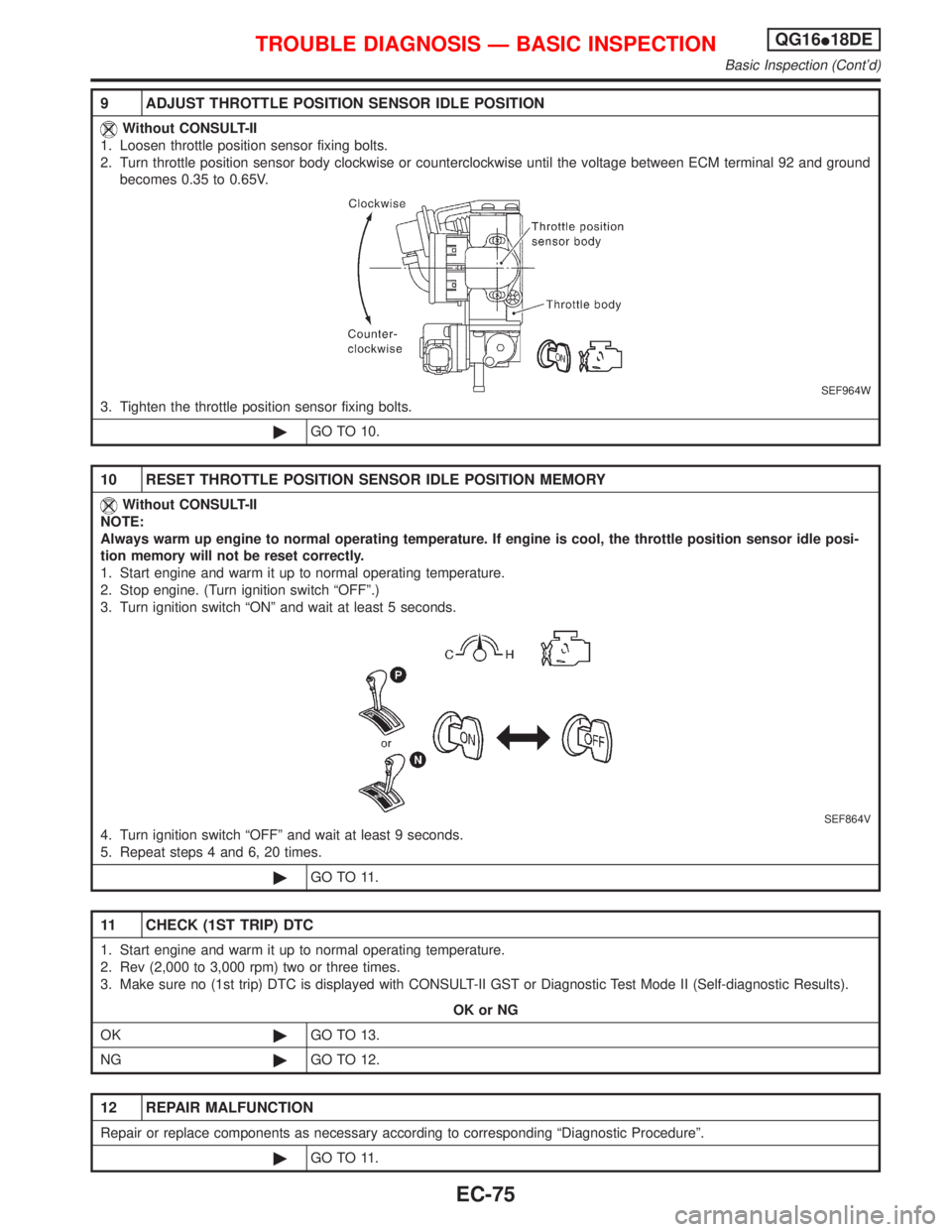
9 ADJUST THROTTLE POSITION SENSOR IDLE POSITION
Without CONSULT-II
1. Loosen throttle position sensor fixing bolts.
2. Turn throttle position sensor body clockwise or counterclockwise until the voltage between ECM terminal 92 and ground
becomes 0.35 to 0.65V.
SEF964W
3. Tighten the throttle position sensor fixing bolts.
©GO TO 10.
10 RESET THROTTLE POSITION SENSOR IDLE POSITION MEMORY
Without CONSULT-II
NOTE:
Always warm up engine to normal operating temperature. If engine is cool, the throttle position sensor idle posi-
tion memory will not be reset correctly.
1. Start engine and warm it up to normal operating temperature.
2. Stop engine. (Turn ignition switch ªOFFº.)
3. Turn ignition switch ªONº and wait at least 5 seconds.
SEF864V
4. Turn ignition switch ªOFFº and wait at least 9 seconds.
5. Repeat steps 4 and 6, 20 times.
©GO TO 11.
11 CHECK (1ST TRIP) DTC
1. Start engine and warm it up to normal operating temperature.
2. Rev (2,000 to 3,000 rpm) two or three times.
3. Make sure no (1st trip) DTC is displayed with CONSULT-II GST or Diagnostic Test Mode II (Self-diagnostic Results).
OK or NG
OK©GO TO 13.
NG©GO TO 12.
12 REPAIR MALFUNCTION
Repair or replace components as necessary according to corresponding ªDiagnostic Procedureº.
©GO TO 11.
TROUBLE DIAGNOSIS Ð BASIC INSPECTIONQG16I18DE
Basic Inspection (Cont'd)
EC-75