1999 NISSAN PRIMERA ESP
[x] Cancel search: ESPPage 217 of 2267
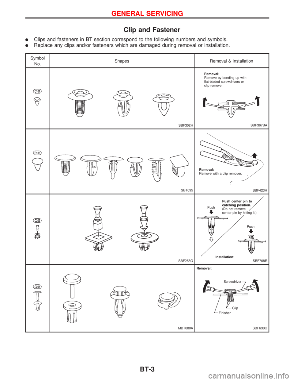
Clip and Fastener
lClips and fasteners in BT section correspond to the following numbers and symbols.
lReplace any clips and/or fasteners which are damaged during removal or installation.
Symbol
No.Shapes Removal & Installation
C101
SBF302HSBF367BA
C103
SBT095SBF423H
C203
SBF258GSBF708E
C205
MBT080ASBF638C Removal:
Remove by bending up with
flat-bladed screwdrivers or
clip remover.
Removal:
Remove with a clip remover.
Push center pin to
catching position.
(Do not remove
center pin by hitting it.) Push
Installation:Push
Removal:
Screwdriver
Clip
Finisher
GENERAL SERVICING
BT-3
Page 300 of 2267
Supplemental Restraint System (SRS) ªAIR
BAGº and ªSEAT BELT PRE-TENSIONERº
NCEC0002
The Supplemental Restraint System ªAIR BAGº and ªSEAT BELT PRE-TENSIONERº, used along with a seat
belt, help to reduce the risk or severity of injury to the driver and front passenger in a frontal collision. The
Supplemental Restraint System consists of air bag modules (located in the center of the steering wheel and
on the instrument panel on the passenger side), seat belt pre-tensioners, a diagnosis sensor unit, warning
lamp, wiring harness and spiral cable.
In addition to the supplemental air bag modules for a frontal collision, the supplemental side air bag used
along with the seat belt helps to reduce the risk or severity of injury to the driver and front passenger in a
side collision. The supplemental side air bag consists of air bag modules (located in the outer side of front
seats), satellite sensor, diagnosis sensor unit (one of components of supplemental air bags for a frontal
collision), wiring harness, warning lamp (one of components of supplemental air bags for a frontal collision).
Information necessary to service the system safely is included in theRS sectionof this Service Manual.
WARNING:
lTo avoid rendering the SRS inoperative, which could increase the risk of personal injury or death
in the event of a collision which would result in air bag inflation, all maintenance must be per-
formed by an authorized NISSAN dealer.
lImproper maintenance, including incorrect removal and installation of the SRS, can lead to per-
sonal injury caused by unintentional activation of the system.
lDo not use electrical test equipment on any circuit related to the SRS unless instructed to in this
Service Manual. SRS wiring harnesses (except ªSEAT BELT PRE-TENSIONERº connector) can be
identified with yellow harness connector (and with yellow harness protector or yellow insulation
tape before the harness connectors).
Precautions for On Board Diagnostic (OBD)
System of Engine
NCEC0003
The ECM has an on board diagnostic system. It will light up the malfunction indicator (MI) to warn the driver
of a malfunction causing emission deterioration.
CAUTION:
lBe sure to turn the ignition switch ªOFFº and disconnect the negative battery terminal before any
repair or inspection work. The open/short circuit of related switches, sensors, solenoid valves,
etc. will cause the MI to light up.
lBe sure to connect and lock the connectors securely after work. A loose (unlocked) connector
will cause the MI to light up due to the open circuit. (Be sure the connector is free from water,
grease, dirt, bent terminals, etc.)
lCertain systems and components, especially those related to OBD, may use a new style slide-
locking type harness connector.
For description and how to disconnect, refer to EL section, ªDescriptionº, ªHARNESS CONNEC-
TORº.
lBe sure to route and secure the harnesses properly after work. The interference of the harness
with a bracket, etc. may cause the MI to light up due to the short circuit.
lBe sure to connect rubber tubes properly after work. A misconnected or disconnected rubber
tube may cause the MI to light up due to the malfunction of the EGR system or fuel injection
system, etc.
lBe sure to erase the unnecessary malfunction information (repairs completed) from the ECM
before returning the vehicle to the customer.
PRECAUTIONS AND PREPARATIONCD20T
EC-6
Page 310 of 2267
IDLE CONTROL
Input/output signal line
Engine coolant temperature sensorEEngine coolant temperature
ECM
EElectric
governor
Crankshaft position sensor (TDC)EEngine speed
Air conditioner switch
EAir conditioner operation
Control sleeve position sensor
EControl sleeve position
Accelerator position switch
EIdle position
Vehicle speed sensor or ABS actuator
and electric unit (control unit)
EVehicle speed
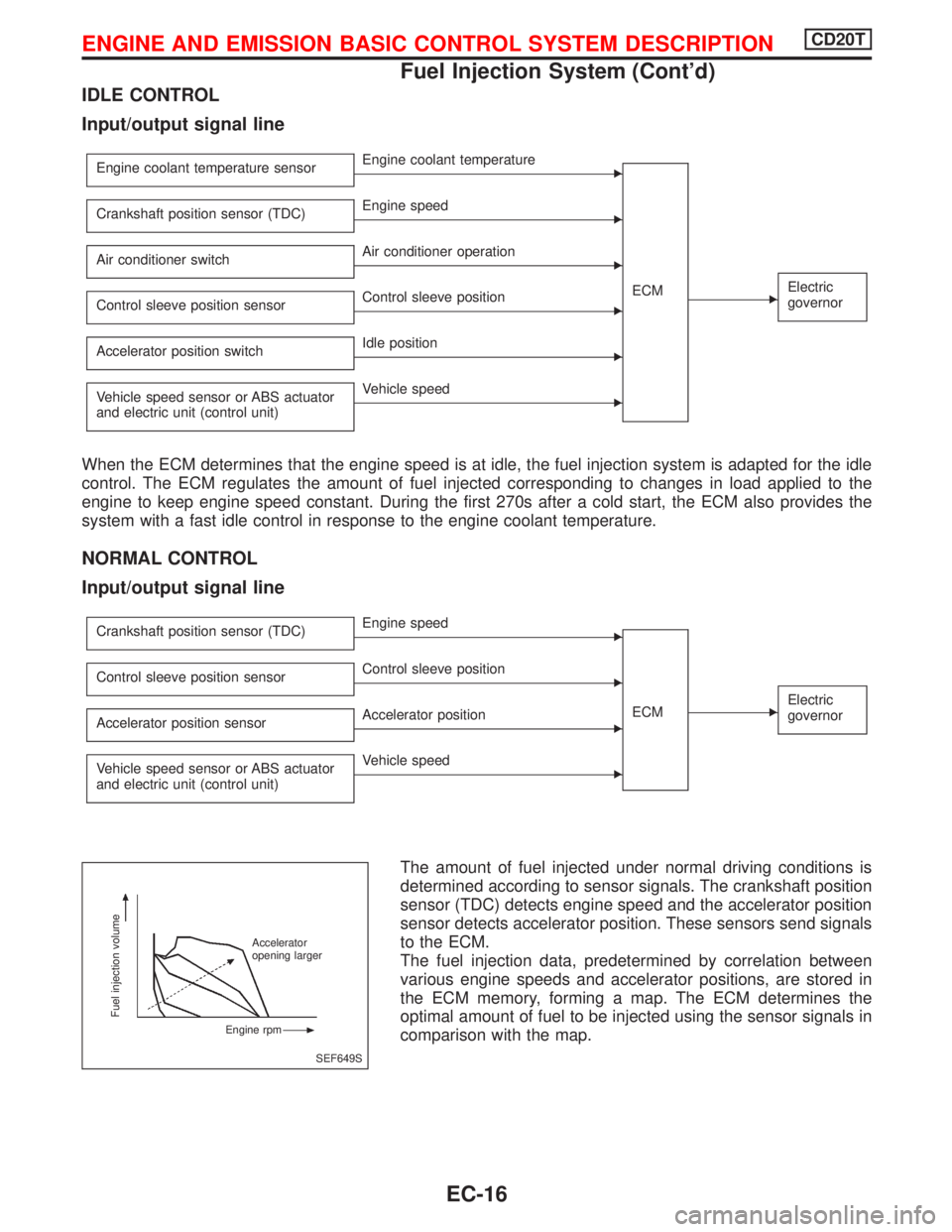
When the ECM determines that the engine speed is at idle, the fuel injection system is adapted for the idle
control. The ECM regulates the amount of fuel injected corresponding to changes in load applied to the
engine to keep engine speed constant. During the first 270s after a cold start, the ECM also provides the
system with a fast idle control in response to the engine coolant temperature.
NORMAL CONTROL
Input/output signal line
Crankshaft position sensor (TDC)EEngine speed
ECM
EElectric
governor
Control sleeve position sensorEControl sleeve position
Accelerator position sensor
EAccelerator position
Vehicle speed sensor or ABS actuator
and electric unit (control unit)
EVehicle speed
The amount of fuel injected under normal driving conditions is
determined according to sensor signals. The crankshaft position
sensor (TDC) detects engine speed and the accelerator position
sensor detects accelerator position. These sensors send signals
to the ECM.
The fuel injection data, predetermined by correlation between
various engine speeds and accelerator positions, are stored in
the ECM memory, forming a map. The ECM determines the
optimal amount of fuel to be injected using the sensor signals in
comparison with the map.
SEF649S
Fuel injection volume
Accelerator
opening larger
Engine rpm
ENGINE AND EMISSION BASIC CONTROL SYSTEM DESCRIPTIONCD20T
Fuel Injection System (Cont'd)
EC-16
Page 314 of 2267
Air Conditioning Cut Control
INPUT/OUTPUT SIGNAL LINE
Air conditioner switch or ABS actuator
and electric unit (control unit)EAir conditioner ªONº signal
ECM
EAir
conditioner
relayAccelerator position sensorEAccelerator valve opening angle
Vehicle speed sensor
EVehicle speed
Engine coolant temperature sensor
EEngine coolant temperature
SYSTEM DESCRIPTION
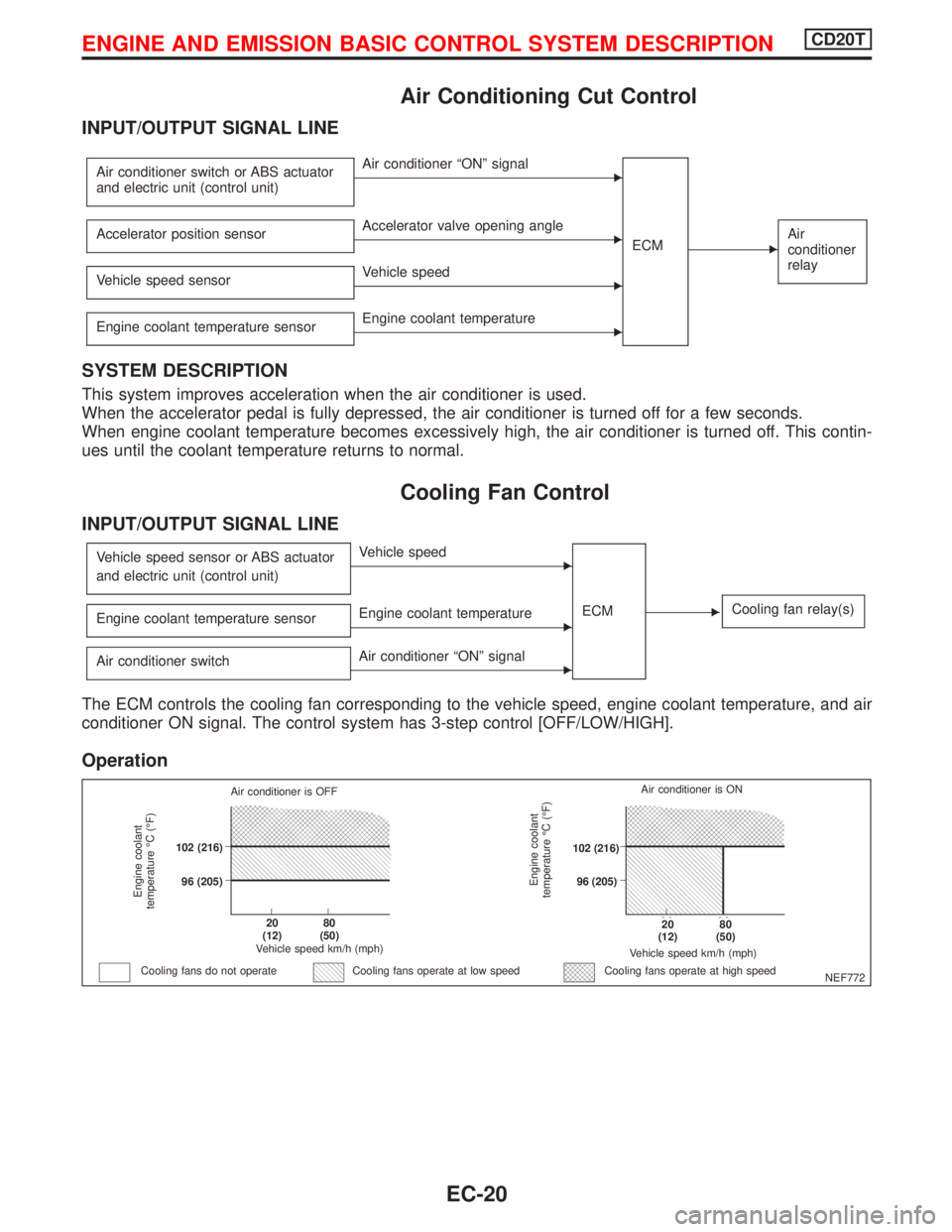
This system improves acceleration when the air conditioner is used.
When the accelerator pedal is fully depressed, the air conditioner is turned off for a few seconds.
When engine coolant temperature becomes excessively high, the air conditioner is turned off. This contin-
ues until the coolant temperature returns to normal.
Cooling Fan Control
INPUT/OUTPUT SIGNAL LINE
Vehicle speed sensor or ABS actuator
and electric unit (control unit)EVehicle speed
ECM
ECooling fan relay(s)Engine coolant temperature sensorEEngine coolant temperature
Air conditioner switch
EAir conditioner ªONº signal
The ECM controls the cooling fan corresponding to the vehicle speed, engine coolant temperature, and air
conditioner ON signal. The control system has 3-step control [OFF/LOW/HIGH].
Operation
NEF772
Engine coolant
temperature ÉC (ÉF)
Air conditioner is OFF
.102 (216)
.96 (205)
.20
(12).80
(50)
Vehicle speed km/h (mph)
Cooling fans do not operateCooling fans operate at high speed
Engine coolant
temperature ÉC (ÉF)
Vehicle speed km/h (mph)
.20
(12).80
(50)
.102 (216)
.96 (205)Air conditioner is ON
Cooling fans operate at low speed
ENGINE AND EMISSION BASIC CONTROL SYSTEM DESCRIPTIONCD20T
EC-20
Page 326 of 2267
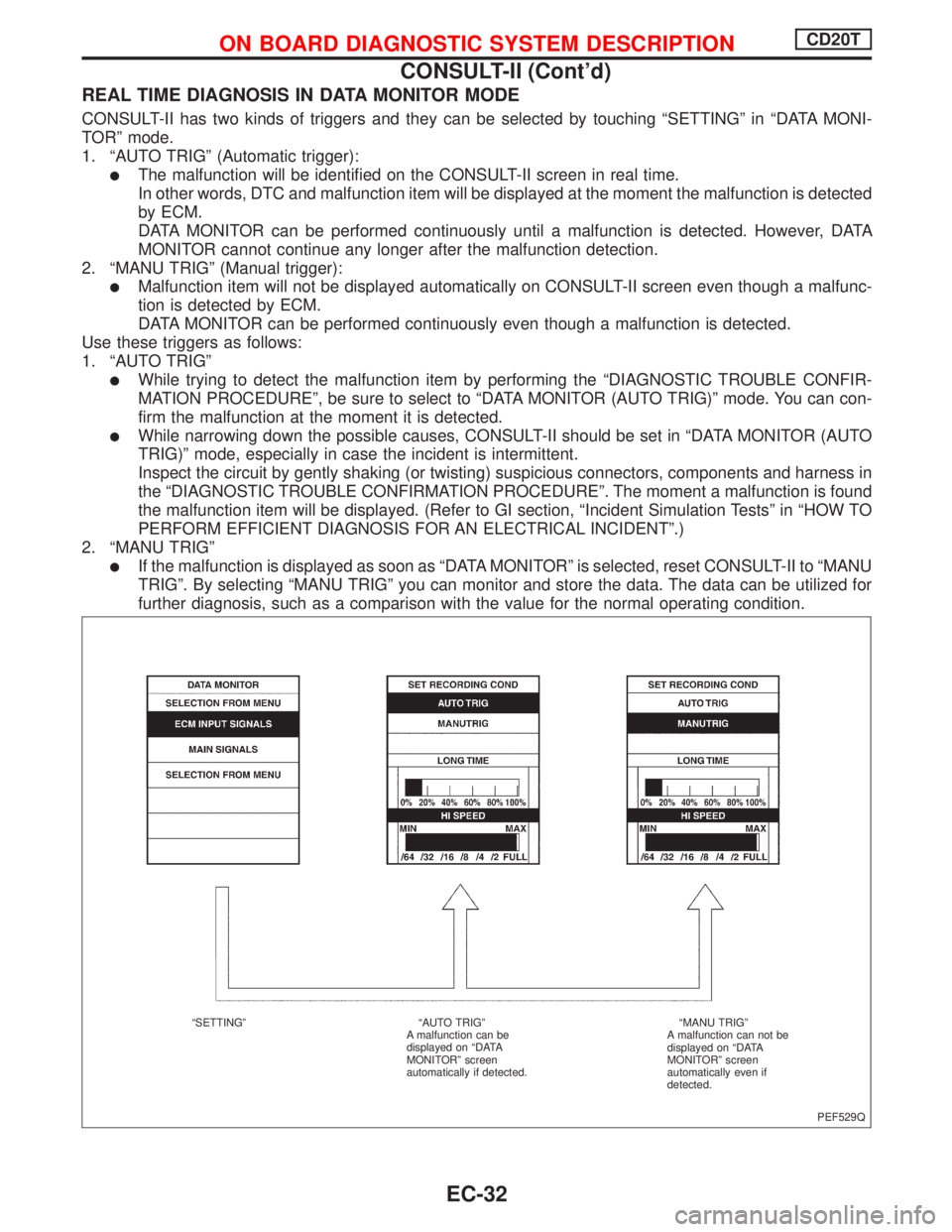
REAL TIME DIAGNOSIS IN DATA MONITOR MODE
CONSULT-II has two kinds of triggers and they can be selected by touching ªSETTINGº in ªDATA MONI-
TORº mode.
1. ªAUTO TRIGº (Automatic trigger):
lThe malfunction will be identified on the CONSULT-II screen in real time.
In other words, DTC and malfunction item will be displayed at the moment the malfunction is detected
by ECM.
DATA MONITOR can be performed continuously until a malfunction is detected. However, DATA
MONITOR cannot continue any longer after the malfunction detection.
2. ªMANU TRIGº (Manual trigger):
lMalfunction item will not be displayed automatically on CONSULT-II screen even though a malfunc-
tion is detected by ECM.
DATA MONITOR can be performed continuously even though a malfunction is detected.
Use these triggers as follows:
1. ªAUTO TRIGº
lWhile trying to detect the malfunction item by performing the ªDIAGNOSTIC TROUBLE CONFIR-
MATION PROCEDUREº, be sure to select to ªDATA MONITOR (AUTO TRIG)º mode. You can con-
firm the malfunction at the moment it is detected.
lWhile narrowing down the possible causes, CONSULT-II should be set in ªDATA MONITOR (AUTO
TRIG)º mode, especially in case the incident is intermittent.
Inspect the circuit by gently shaking (or twisting) suspicious connectors, components and harness in
the ªDIAGNOSTIC TROUBLE CONFIRMATION PROCEDUREº. The moment a malfunction is found
the malfunction item will be displayed. (Refer to GI section, ªIncident Simulation Testsº in ªHOW TO
PERFORM EFFICIENT DIAGNOSIS FOR AN ELECTRICAL INCIDENTº.)
2. ªMANU TRIGº
lIf the malfunction is displayed as soon as ªDATA MONITORº is selected, reset CONSULT-II to ªMANU
TRIGº. By selecting ªMANU TRIGº you can monitor and store the data. The data can be utilized for
further diagnosis, such as a comparison with the value for the normal operating condition.
PEF529Q ªSETTINGº ªAUTO TRIGº
A malfunction can be
displayed on ªDATA
MONITORº screen
automatically if detected.ªMANU TRIGº
A malfunction can not be
displayed on ªDATA
MONITORº screen
automatically even if
detected.
ON BOARD DIAGNOSTIC SYSTEM DESCRIPTIONCD20T
CONSULT-II (Cont'd)
EC-32
Page 327 of 2267
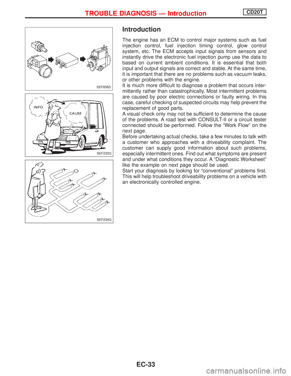
Introduction
The engine has an ECM to control major systems such as fuel
injection control, fuel injection timing control, glow control
system, etc. The ECM accepts input signals from sensors and
instantly drive the electronic fuel injection pump use the data to
based on current ambient conditions. It is essential that both
input and output signals are correct and stable. At the same time,
it is important that there are no problems such as vacuum leaks,
or other problems with the engine.
It is much more difficult to diagnose a problem that occurs inter-
mittently rather than catastrophically. Most intermittent problems
are caused by poor electric connections or faulty wiring. In this
case, careful checking of suspected circuits may help prevent the
replacement of good parts.
A visual check only may not be sufficient to determine the cause
of the problems. A road test with CONSULT-II or a circuit tester
connected should be performed. Follow the ªWork Flowº on the
next page.
Before undertaking actual checks, take a few minutes to talk with
a customer who approaches with a driveability complaint. The
customer can supply good information about such problems,
especially intermittent ones. Find out what symptoms are present
and under what conditions they occur. A ªDiagnostic Worksheetº
like the example on next page should be used.
Start your diagnosis by looking for ªconventionalº problems first.
This will help troubleshoot driveability problems on a vehicle with
an electronically controlled engine.
SEF858S
SEF233G
SEF234G
TROUBLE DIAGNOSIS Ð IntroductionCD20T
EC-33
Page 381 of 2267
Cooling Fan (Overheat)
SYSTEM DESCRIPTION
Vehicle speed sensorEVehicle speed
ECM
ECooling
fan
relay(s)Engine coolant temperature sensorEEngine coolant temperature
Air conditioner switch
EAir conditioner ªONº signal
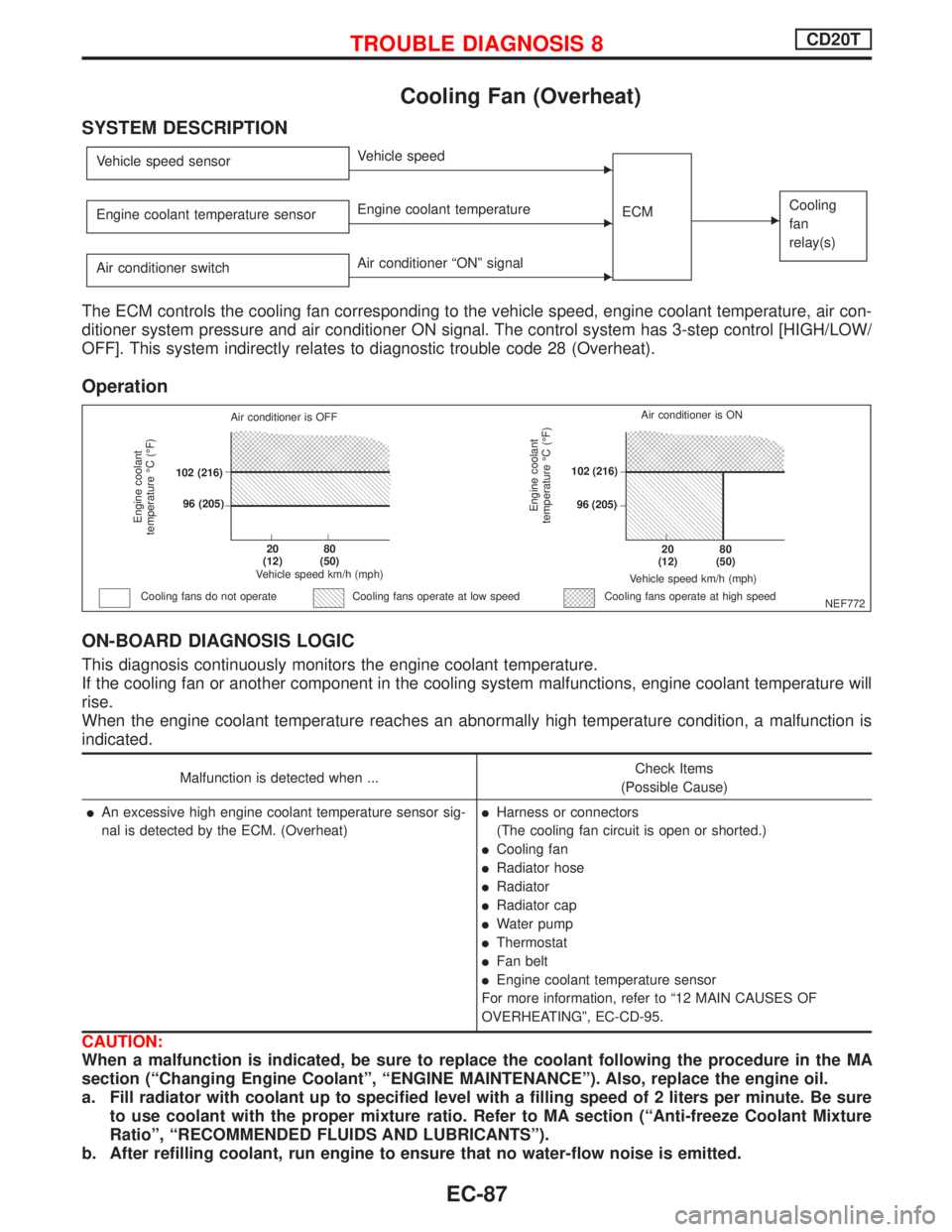
The ECM controls the cooling fan corresponding to the vehicle speed, engine coolant temperature, air con-
ditioner system pressure and air conditioner ON signal. The control system has 3-step control [HIGH/LOW/
OFF]. This system indirectly relates to diagnostic trouble code 28 (Overheat).
Operation
ON-BOARD DIAGNOSIS LOGIC
This diagnosis continuously monitors the engine coolant temperature.
If the cooling fan or another component in the cooling system malfunctions, engine coolant temperature will
rise.
When the engine coolant temperature reaches an abnormally high temperature condition, a malfunction is
indicated.
Malfunction is detected when ...Check Items
(Possible Cause)
lAn excessive high engine coolant temperature sensor sig-
nal is detected by the ECM. (Overheat)lHarness or connectors
(The cooling fan circuit is open or shorted.)
lCooling fan
lRadiator hose
lRadiator
lRadiator cap
lWater pump
lThermostat
lFan belt
lEngine coolant temperature sensor
For more information, refer to ª12 MAIN CAUSES OF
OVERHEATINGº, EC-CD-95.
CAUTION:
When a malfunction is indicated, be sure to replace the coolant following the procedure in the MA
section (ªChanging Engine Coolantº, ªENGINE MAINTENANCEº). Also, replace the engine oil.
a. Fill radiator with coolant up to specified level with a filling speed of 2 liters per minute. Be sure
to use coolant with the proper mixture ratio. Refer to MA section (ªAnti-freeze Coolant Mixture
Ratioº, ªRECOMMENDED FLUIDS AND LUBRICANTSº).
b. After refilling coolant, run engine to ensure that no water-flow noise is emitted.
NEF772
Engine coolant
temperature ÉC (ÉF)
Air conditioner is OFF
.102 (216)
.96 (205)
.20
(12).80
(50)
Vehicle speed km/h (mph)
Cooling fans do not operateCooling fans operate at high speed
Engine coolant
temperature ÉC (ÉF)
Vehicle speed km/h (mph)
.20
(12).80
(50)
.102 (216)
.96 (205)Air conditioner is ON
Cooling fans operate at low speed
TROUBLE DIAGNOSIS 8CD20T
EC-87
Page 412 of 2267
Glow Control System
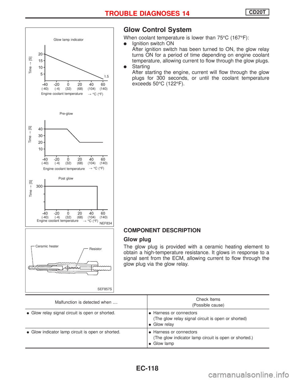
When coolant temperature is lower than 75ÉC (167ÉF):
lIgnition switch ON
After ignition switch has been turned to ON, the glow relay
turns ON for a period of time depending on engine coolant
temperature, allowing current to flow through the glow plugs.
lStarting
After starting the engine, current will flow through the glow
plugs for 300 seconds, or until the coolant temperature
exceeds 50ÉC (122ÉF).
COMPONENT DESCRIPTION
Glow plug
The glow plug is provided with a ceramic heating element to
obtain a high-temperature resistance. It glows in response to a
signal sent from the ECM, allowing current to flow through the
glow plug via the glow relay.
Malfunction is detected when ....Check Items
(Possible cause)
lGlow relay signal circuit is open or shorted.lHarness or connectors
(The glow relay signal circuit is open or shorted)
lGlow relay
lGlow indicator lamp circuit is open or shorted.lHarness or connectors
(The glow indicator lamp circuit is open or shorted.)
lGlow lamp
Glow lamp indicator
Time,[S]
.
Engine coolant temperature
Pre-glow
Time,[S]
Engine coolant temperature.
Post glow
.Time,[S]
Engine coolant temperature
.1.5
.(-40) (-4) (32) (68) (104) (140)
.(-40) (-4) (32) (68) (104) (140)
.(-40) (-4) (32) (68) (104) (140),ÉC (ÉF).,ÉC (ÉF)
.,ÉC (ÉF)
NEF834
.
.
SEF857S Ceramic heater
Resistor
TROUBLE DIAGNOSES 14CD20T
EC-118