Page 819 of 2267
Circuit DiagramNCEC0010
YEC080A
ENGINE AND EMISSION CONTROL OVERALL SYSTEMSR20DE
Circuit Diagram
EC-19
Page 820 of 2267
System DiagramNCEC0011
YEC117A
ENGINE AND EMISSION CONTROL OVERALL SYSTEMSR20DE
System Diagram
EC-20
Page 821 of 2267
Vacuum Hose DrawingNCEC0012Refer to ªSystem Diagramº on EC-SR-20 for vacuum control system.
NOTE:
Do not use soapy water or any type of solvent while installing vacuum hoses or purge hoses.
SEF191X Intake manifold collector
Throttle body
Rear view (Left side)Rear view (Right side)
Intake manifold collector
Fuel pressure
regulator
To brake
booster
Air hose to
power steering
air valve
EVAP purge line to engine
Fuel filter
To EVAP
canister
(RHD models)
EVAP purge volume
control solenoid valve
To EVAP
canister
(LHD models)
Front view
EVAP purge
line to
engine
EVAP canister
(LHD models)
Power steering air valve
To intake manifold
collector
Air tube for power
steering air valve
To EVAP
canister
(RHD models)
ENGINE AND EMISSION CONTROL OVERALL SYSTEMSR20DE
Vacuum Hose Drawing
EC-21
Page 915 of 2267
Main Power Supply and Ground Circuit
WIRING DIAGRAMNCEC0047
YEC828
BATTERY
Refer to EL-POWER.
OFF
ACCST
ONIGNITION
SWITCH
FUSE
BLOCK
(J/B)
To EC-IBN/SG,
EC-TP/SW,
EC-AAC/V,
EC-EGR ECM
RELAY
ECM
: Detectable line for DTC
: Non-detectable line for DTC
: Hyper CVT models
: M/T models
.REFER TO THE FOLLOWING
M1FUSE BLOCK -
Junction Box (J/B)
E103FUSE BLOCK -
Junction Box (J/B)
H1:C17M23
TROUBLE DIAGNOSIS FOR POWER SUPPLYSR20DE
Main Power Supply and Ground Circuit
EC-115
Page 917 of 2267

3 DETECT MALFUNCTIONING PART
Check the following.
IFuse 10A, 40A
IHarness connectors M50, F104 (CVT: M81, F115)
IHarness for open or short between ECM and fuse block
IHarness for open or short between fuse block and ignition switch. Refer to wiring diagram.
©Repair harness or connectors.
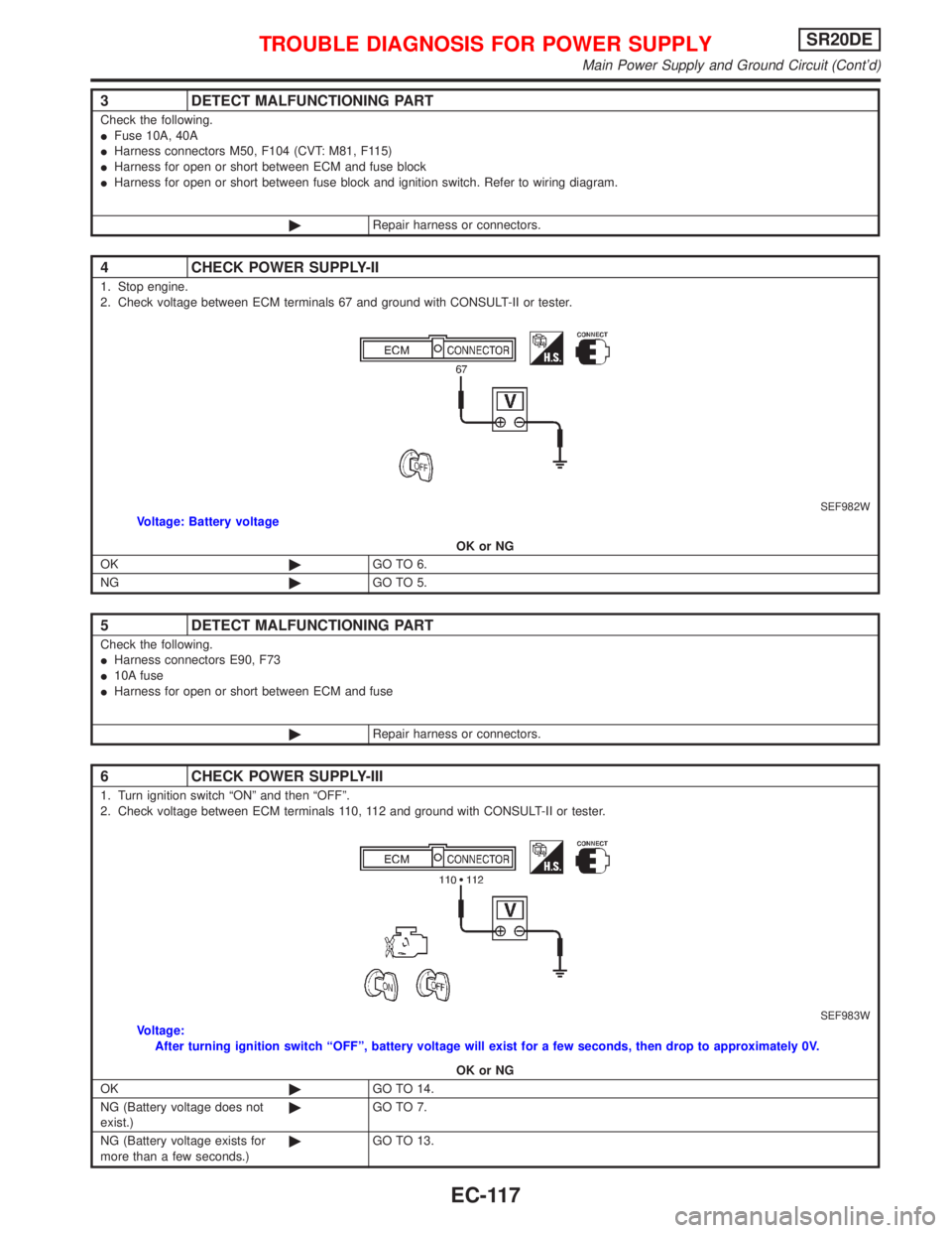
4 CHECK POWER SUPPLY-II
1. Stop engine.
2. Check voltage between ECM terminals 67 and ground with CONSULT-II or tester.
SEF982WVoltage: Battery voltage
OK or NG
OK©GO TO 6.
NG©GO TO 5.
5 DETECT MALFUNCTIONING PART
Check the following.
IHarness connectors E90, F73
I10A fuse
IHarness for open or short between ECM and fuse
©Repair harness or connectors.
6 CHECK POWER SUPPLY-III
1. Turn ignition switch ªONº and then ªOFFº.
2. Check voltage between ECM terminals 110, 112 and ground with CONSULT-II or tester.
SEF983WVoltage:
After turning ignition switch ªOFFº, battery voltage will exist for a few seconds, then drop to approximately 0V.
OK or NG
OK©GO TO 14.
NG (Battery voltage does not
exist.)©GO TO 7.
NG (Battery voltage exists for
more than a few seconds.)©GO TO 13.
TROUBLE DIAGNOSIS FOR POWER SUPPLYSR20DE
Main Power Supply and Ground Circuit (Cont'd)
EC-117
Page 918 of 2267
7 CHECK HARNESS CONTINUITY BETWEEN ECM RELAY AND ECM
1. Disconnect ECM harness connector.
2. Disconnect ECM relay.
SEF984W3. Check harness continuity between ECM terminals 110, 112 and relay terminal 5.
Refer to wiring diagram.
Continuity should exist.
4. Also check harness for short to ground and short to power.
OK or NG
OK©GO TO 9.
NG©GO TO 8.
8 DETECT MALFUNCTIONING PART
Check the following.
IHarness connectors E90, F73
IHarness for open or short between ECM relay and ECM
©Repair open circuit or short to ground or short to power in harness or connectors.
9 CHECK VOLTAGE BETWEEN ECM RELAY AND GROUND
Check voltage between relay terminals 1, 3 and ground with CONSULT-II or tester.
SEF985WVoltage: Battery voltage
OK or NG
OK©GO TO 11.
NG©GO TO 10.
10 DETECT MALFUNCTIONING PART
Check the harness for open or short between ECM relay and fuse.
©Repair harness or connectors.
TROUBLE DIAGNOSIS FOR POWER SUPPLYSR20DE
Main Power Supply and Ground Circuit (Cont'd)
EC-118
Page 919 of 2267

11 CHECK OUTPUT SIGNAL CIRCUIT
1. Check harness continuity between ECM terminal 31 and relay terminal 2.
Refer to wiring diagram.
Continuity should exist.
2. Also check harness for short to ground and short to power.
OK or NG
OK©GO TO 13.
NG©GO TO 12.
12 DETECT MALFUNCTIONING PART
Check the following.
IHarness connectors E42, F4
IHarness for open or short between ECM relay and ECM
©Repair open circuit or short to ground or short to power in harness or connectors.
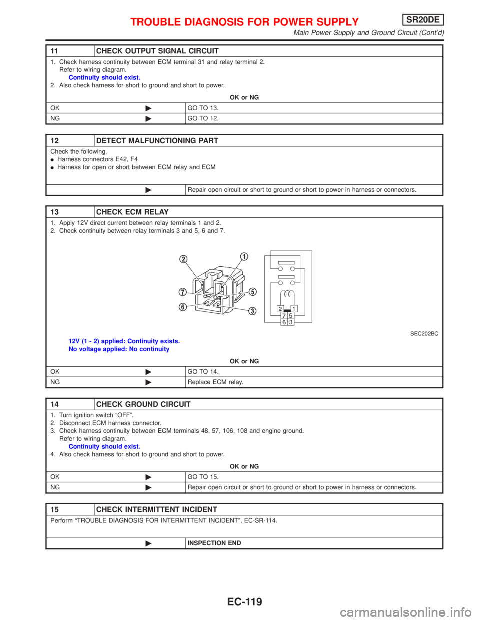
13 CHECK ECM RELAY
1. Apply 12V direct current between relay terminals 1 and 2.
2. Check continuity between relay terminals 3 and 5, 6 and 7.
SEC202BC12V (1 - 2) applied: Continuity exists.
No voltage applied: No continuity
OK or NG
OK©GO TO 14.
NG©Replace ECM relay.
14 CHECK GROUND CIRCUIT
1. Turn ignition switch ªOFFº.
2. Disconnect ECM harness connector.
3. Check harness continuity between ECM terminals 48, 57, 106, 108 and engine ground.
Refer to wiring diagram.
Continuity should exist.
4. Also check harness for short to ground and short to power.
OK or NG
OK©GO TO 15.
NG©Repair open circuit or short to ground or short to power in harness or connectors.
15 CHECK INTERMITTENT INCIDENT
Perform ªTROUBLE DIAGNOSIS FOR INTERMITTENT INCIDENTº, EC-SR-114.
©INSPECTION END
TROUBLE DIAGNOSIS FOR POWER SUPPLYSR20DE
Main Power Supply and Ground Circuit (Cont'd)
EC-119
Page 922 of 2267
Wiring DiagramNCEC0056
YEC081A
DTC P0100 MASS AIR FLOW SENSOR (MAFS)SR20DE
Wiring Diagram
EC-122