Page 1004 of 2267

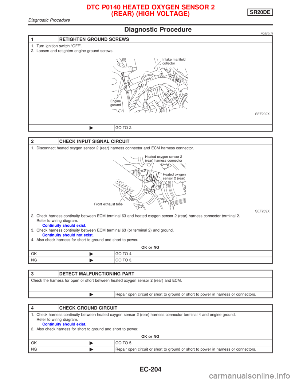
Diagnostic ProcedureNCEC0178
1 RETIGHTEN GROUND SCREWS
1. Turn ignition switch ªOFFº.
2. Loosen and retighten engine ground screws.
SEF202X
©GO TO 2.
2 CHECK INPUT SIGNAL CIRCUIT
1. Disconnect heated oxygen sensor 2 (rear) harness connector and ECM harness connector.
SEF209X2. Check harness continuity between ECM terminal 63 and heated oxygen sensor 2 (rear) harness connector terminal 2.
Refer to wiring diagram.
Continuity should exist.
3. Check harness continuity between ECM terminal 63 (or terminal 2) and ground.
Continuity should not exist.
4. Also check harness for short to ground and short to power.
OK or NG
OK©GO TO 4.
NG©GO TO 3.
3 DETECT MALFUNCTIONING PART
Check the harness for open or short between heated oxygen sensor 2 (rear) and ECM.
©Repair open circuit or short to ground or short to power in harness or connectors.
4 CHECK GROUND CIRCUIT
1. Check harness continuity between heated oxygen sensor 2 (rear) harness connector terminal 4 and engine ground.
Refer to wiring diagram.
Continuity should exist.
2. Also check harness for short to ground and short to power.
OK or NG
OK©GO TO 5.
NG©Repair open circuit or short to ground or short to power in harness or connectors.
Intake manifold
collector
Engine
ground
Heated oxygen sensor 2
(rear) harness connector
Heated oxygen
sensor 2 (rear)
Front exhaust tube
DTC P0140 HEATED OXYGEN SENSOR 2
(REAR) (HIGH VOLTAGE)SR20DE
Diagnostic Procedure
EC-204
Page 1009 of 2267
Wiring DiagramNCEC0185
YEC087A
DTC P0141 HEATED OXYGEN SENSOR 2 (REAR) HEATERSR20DE
Wiring Diagram
EC-209
Page 1010 of 2267

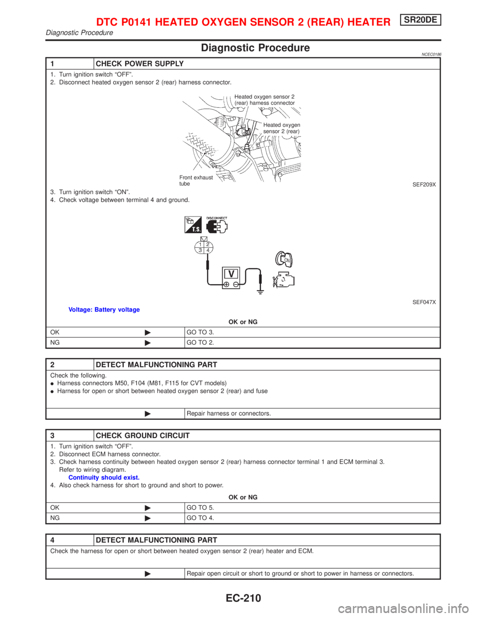
Diagnostic ProcedureNCEC0186
1 CHECK POWER SUPPLY
1. Turn ignition switch ªOFFº.
2. Disconnect heated oxygen sensor 2 (rear) harness connector.
SEF209X3. Turn ignition switch ªONº.
4. Check voltage between terminal 4 and ground.
SEF047XVoltage: Battery voltage
OK or NG
OK©GO TO 3.
NG©GO TO 2.
2 DETECT MALFUNCTIONING PART
Check the following.
IHarness connectors M50, F104 (M81, F115 for CVT models)
IHarness for open or short between heated oxygen sensor 2 (rear) and fuse
©Repair harness or connectors.
3 CHECK GROUND CIRCUIT
1. Turn ignition switch ªOFFº.
2. Disconnect ECM harness connector.
3. Check harness continuity between heated oxygen sensor 2 (rear) harness connector terminal 1 and ECM terminal 3.
Refer to wiring diagram.
Continuity should exist.
4. Also check harness for short to ground and short to power.
OK or NG
OK©GO TO 5.
NG©GO TO 4.
4 DETECT MALFUNCTIONING PART
Check the harness for open or short between heated oxygen sensor 2 (rear) heater and ECM.
©Repair open circuit or short to ground or short to power in harness or connectors.
Heated oxygen sensor 2
(rear) harness connector
Heated oxygen
sensor 2 (rear)
Front exhaust
tube
DTC P0141 HEATED OXYGEN SENSOR 2 (REAR) HEATERSR20DE
Diagnostic Procedure
EC-210
Page 1013 of 2267
Wiring DiagramNCEC0190
YEC088A
DTC P0171 FUEL INJECTION SYSTEM FUNCTION
(LEAN SIDE)SR20DE
Wiring Diagram
EC-213
Page 1014 of 2267

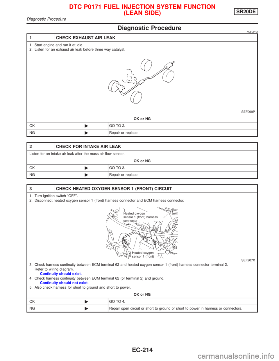
Diagnostic ProcedureNCEC0191
1 CHECK EXHAUST AIR LEAK
1. Start engine and run it at idle.
2. Listen for an exhaust air leak before three way catalyst.
SEF099P
OK or NG
OK©GO TO 2.
NG©Repair or replace.
2 CHECK FOR INTAKE AIR LEAK
Listen for an intake air leak after the mass air flow sensor.
OK or NG
OK©GO TO 3.
NG©Repair or replace.
3 CHECK HEATED OXYGEN SENSOR 1 (FRONT) CIRCUIT
1. Turn ignition switch ªOFFº.
2. Disconnect heated oxygen sensor 1 (front) harness connector and ECM harness connector.
SEF207X3. Check harness continuity between ECM terminal 62 and heated oxygen sensor 1 (front) harness connector terminal 2.
Refer to wiring diagram.
Continuity should exist.
4. Check harness continuity between ECM terminal 62 (or terminal 2) and ground.
Continuity should not exist.
5. Also check harness for short to ground and short to power.
OK or NG
OK©GO TO 4.
NG©Repair open circuit or short to ground or short to power in harness or connectors.
Heated oxygen
sensor 1 (front) harness
connector
Heated oxygen
sensor 1 (front)
DTC P0171 FUEL INJECTION SYSTEM FUNCTION
(LEAN SIDE)SR20DE
Diagnostic Procedure
EC-214
Page 1020 of 2267
Wiring DiagramNCEC0194
YEC088A
DTC P0172 FUEL INJECTION SYSTEM FUNCTION
(RICH SIDE)SR20DE
Wiring Diagram
EC-220
Page 1021 of 2267

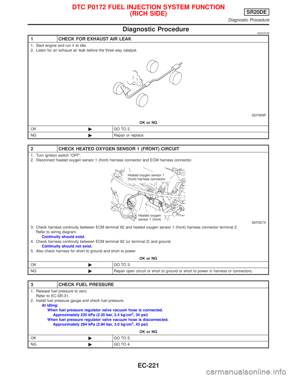
Diagnostic ProcedureNCEC0195
1 CHECK FOR EXHAUST AIR LEAK
1. Start engine and run it at idle.
2. Listen for an exhaust air leak before the three way catalyst.
SEF099P
OK or NG
OK©GO TO 2.
NG©Repair or replace.
2 CHECK HEATED OXYGEN SENSOR 1 (FRONT) CIRCUIT
1. Turn ignition switch ªOFFº.
2. Disconnect heated oxygen sensor 1 (front) harness connector and ECM harness connector.
SEF207X3. Check harness continuity between ECM terminal 62 and heated oxygen sensor 1 (front) harness connector terminal 2.
Refer to wiring diagram.
Continuity should exist.
4. Check harness continuity between ECM terminal 62 (or terminal 2) and ground.
Continuity should not exist.
5. Also check harness for short to ground and short to power.
OK or NG
OK©GO TO 3.
NG©Repair open circuit or short to ground or short to power in harness or connectors.
3 CHECK FUEL PRESSURE
1. Release fuel pressure to zero.
Refer to EC-SR-31.
2. Install fuel pressure gauge and check fuel pressure.
At idling:
When fuel pressure regulator valve vacuum hose is connected.
Approximately 235 kPa (2.35 bar, 2.4 kg/cm
2, 34 psi)
When fuel pressure regulator valve vacuum hose is disconnected.
Approximately 294 kPa (2.94 bar, 3.0 kg/cm
2, 43 psi)
OK or NG
OK©GO TO 5.
NG©GO TO 4.
Heated oxygen sensor 1
(front) harness connector
Heated oxygen
sensor 1 (front)
DTC P0172 FUEL INJECTION SYSTEM FUNCTION
(RICH SIDE)SR20DE
Diagnostic Procedure
EC-221
Page 1031 of 2267
Wiring DiagramNCEC0210
YEC089A
DTC P0325 KNOCK SENSOR (KS)SR20DE
Wiring Diagram
EC-231