Page 1093 of 2267

Diagnostic ProcedureNCEC0332
1 RETIGHTEN GROUND SCREWS
1. Turn ignition switch ªOFFº.
2. Loosen and retighten engine ground screws.
©GO TO 2.
2 CHECK INPUT SIGNAL CIRCUIT
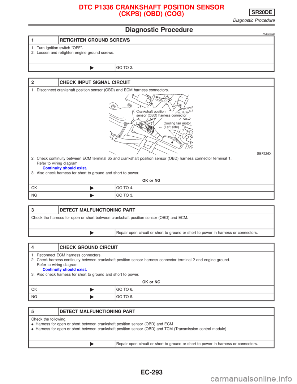
1. Disconnect crankshaft position sensor (OBD) and ECM harness connectors.
SEF226X2. Check continuity between ECM terminal 65 and crankshaft position sensor (OBD) harness connector terminal 1.
Refer to wiring diagram.
Continuity should exist.
3. Also check harness for short to ground and short to power.
OK or NG
OK©GO TO 4.
NG©GO TO 3.
3 DETECT MALFUNCTIONING PART
Check the harness for open or short between crankshaft position sensor (OBD) and ECM.
©Repair open circuit or short to ground or short to power in harness or connectors.
4 CHECK GROUND CIRCUIT
1. Reconnect ECM harness connectors.
2. Check harness continuity between crankshaft position sensor harness connector terminal 2 and engine ground.
Refer to wiring diagram.
Continuity should exist.
3. Also check harness for short to ground and short to power.
OK or NG
OK©GO TO 6.
NG©GO TO 5.
5 DETECT MALFUNCTIONING PART
Check the following.
IHarness for open or short between crankshaft position sensor (OBD) and ECM
IHarness for open or short between crankshaft position sensor (OBD) and TCM (Transmission control module)
©Repair open circuit or short to ground or short to power in harness or connectors.
Crankshaft position
sensor (OBD) harness connector
Cooling fan motor
(Left side)
DTC P1336 CRANKSHAFT POSITION SENSOR
(CKPS) (OBD) (COG)SR20DE
Diagnostic Procedure
EC-293
Page 1096 of 2267
Wiring DiagramNCEC0564
YEC850
: Detectable line for DTC
: Non-detectable line for DTC TCM
(TRANSMISSION
CONTROL
MODULE)
ECM
F101
.ATCK
DTC P1605 A/T DIAGNOSIS COMMUNICATION LINESR20DE
Wiring Diagram
EC-296
Page 1097 of 2267
Diagnostic ProcedureNCEC0565
1 CHECK INPUT SIGNAL CIRCUIT
1. Turn ignition switch ªOFFº.
2. Disconnect ECM harness connector and TCM harness connector. Refer to A/T section for TCM location.
3. Check harness continuity between ECM terminal 91 and TCM terminal 15. Refer to wiring diagram.
4. Also check harness for short to ground and short to power.
OK or NG
OK©GO TO 2.
NG©Repair open circuit or short to ground or short to power in harness or connectors.
2 CHECK INTERMITTENT INCIDENT
Perform ªTROUBLE DIAGNOSIS FOR INTERMITTENT INCIDENTº, EC-SR-114.
©INSPECTION END
DTC P1605 A/T DIAGNOSIS COMMUNICATION LINESR20DE
Diagnostic Procedure
EC-297
Page 1100 of 2267
Wiring DiagramNCEC0430
YEC851
: Detectable line for DTC
: Non-detectable line for DTC
: Hyper CVT models
: M/T models ECM
PARK/NEUTRAL
POSITION
SWITCH NEUTRAL
POSITION
SWITCH NEUTRAL
OTHERSP
R
NDDs
DTC P1706 PARK/NEUTRAL POSITION (PNP) SWITCHSR20DE
Wiring Diagram
EC-300
Page 1101 of 2267

Diagnostic ProcedureNCEC0431
1 CHECK GROUND CIRCUIT
1. Turn ignition switch ªOFFº.
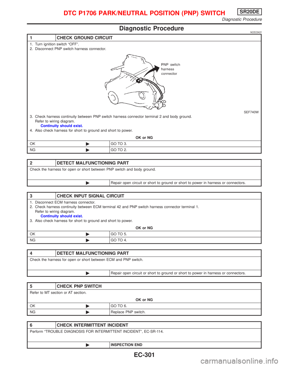
2. Disconnect PNP switch harness connector.
SEF740W3. Check harness continuity between PNP switch harness connector terminal 2 and body ground.
Refer to wiring diagram.
Continuity should exist.
4. Also check harness for short to ground and short to power.
OK or NG
OK©GO TO 3.
NG©GO TO 2.
2 DETECT MALFUNCTIONING PART
Check the harness for open or short between PNP switch and body ground.
©Repair open circuit or short to ground or short to power in harness or connectors.
3 CHECK INPUT SIGNAL CIRCUIT
1. Disconnect ECM harness connector.
2. Check harness continuity between ECM terminal 42 and PNP switch harness connector terminal 1.
Refer to wiring diagram.
Continuity should exist.
3. Also check harness for short to ground and short to power.
OK or NG
OK©GO TO 5.
NG©GO TO 4.
4 DETECT MALFUNCTIONING PART
Check the harness for open or short between ECM and PNP switch.
©Repair open circuit or short to ground or short to power in harness or connectors.
5 CHECK PNP SWITCH
Refer to MT section or AT section.
OK or NG
OK©GO TO 6.
NG©Replace PNP switch.
6 CHECK INTERMITTENT INCIDENT
Perform ªTROUBLE DIAGNOSIS FOR INTERMITTENT INCIDENTº, EC-SR-114.
©INSPECTION END
DTC P1706 PARK/NEUTRAL POSITION (PNP) SWITCHSR20DE
Diagnostic Procedure
EC-301
Page 1103 of 2267
Wiring DiagramNCEC0434
YEC251
IGNITION SWITCH
ON or START
Refer to
EL-POWER.Detectable line for DTC
Non-detectable line for DTC
Hyper CVT models
M/T models FUSE
BLOCK
(J/B)
INJECTOR
No.4
ECM
REFER TO THE FOLLOWING
FUSE BLOCK -
Junction Box (J/B) INJECTOR
No.1INJECTOR
No.2INJECTOR
No.3
INJECTORSR20DE
Wiring Diagram
EC-303
Page 1105 of 2267
![NISSAN PRIMERA 1999 Electronic Repair Manual Component InspectionNCEC0439INJECTORNCEC0439S011. Disconnect injector harness connector.
2. Check resistance between terminals as shown in the figure.
Resistance: 13.5 - 17.5W[at 25ÉC (77ÉF)]
If NG, NISSAN PRIMERA 1999 Electronic Repair Manual Component InspectionNCEC0439INJECTORNCEC0439S011. Disconnect injector harness connector.
2. Check resistance between terminals as shown in the figure.
Resistance: 13.5 - 17.5W[at 25ÉC (77ÉF)]
If NG,](/manual-img/5/57377/w960_57377-1104.png)
Component InspectionNCEC0439INJECTORNCEC0439S011. Disconnect injector harness connector.
2. Check resistance between terminals as shown in the figure.
Resistance: 13.5 - 17.5W[at 25ÉC (77ÉF)]
If NG, replace injector.
3 DETECT MALFUNCTIONING PART
Check the following.
I10A fuse
IHarness connectors F13, F60
IHarness connectors M50, F104 (CVT: M81, F115)
IHarness for open or short between injector and fuse
©Repair harness or connectors.
4 CHECK OUTPUT SIGNAL CIRCUIT
1. Turn ignition switch ªOFFº.
2. Disconnect ECM harness connector.
3. Check harness continuity between injector harness connector terminal 1 and ECM terminals 101, 103, 105, 107.
Refer to wiring diagram.
Continuity should exist.
4. Also check harness for short to ground and short to power.
OK or NG
OK©GO TO 6.
NG©GO TO 5.
5 DETECT MALFUNCTIONING PART
Check the following.
IHarness connectors F13, F60
IHarness for open or short between ECM and injector
©Repair open circuit or short to ground or short to power in harness or connectors.
6 CHECK INJECTOR
Refer to ªComponent Inspectionº, EC-SR-305.
OK or NG
OK©GO TO 7.
NG©Replace injector.
7 CHECK INTERMITTENT INCIDENT
Perform ªTROUBLE DIAGNOSIS FOR INTERMITTENT INCIDENTº, EC-SR-114.
©INSPECTION END
SEF139X
INJECTORSR20DE
Component Inspection
EC-305
Page 1108 of 2267
Wiring DiagramNCEC0571
YEC852
ECM
RELAY
DISTRIBUTOR Refer to
EL-POWER. BATTERY
RESISTOR
SPARK
PLUGIGNITION
COILCONDENSER
POWER
TRANSISTOR
IGNITION SIGNALSR20DE
Wiring Diagram
EC-308