Page 1109 of 2267

Diagnostic ProcedureNCEC0572
1 CHECK ENGINE START
Turn ignition switch ªOFFº, and restart engine.
Is engine running?
YesorNo
Ye s©GO TO 7.
No©GO TO 2.
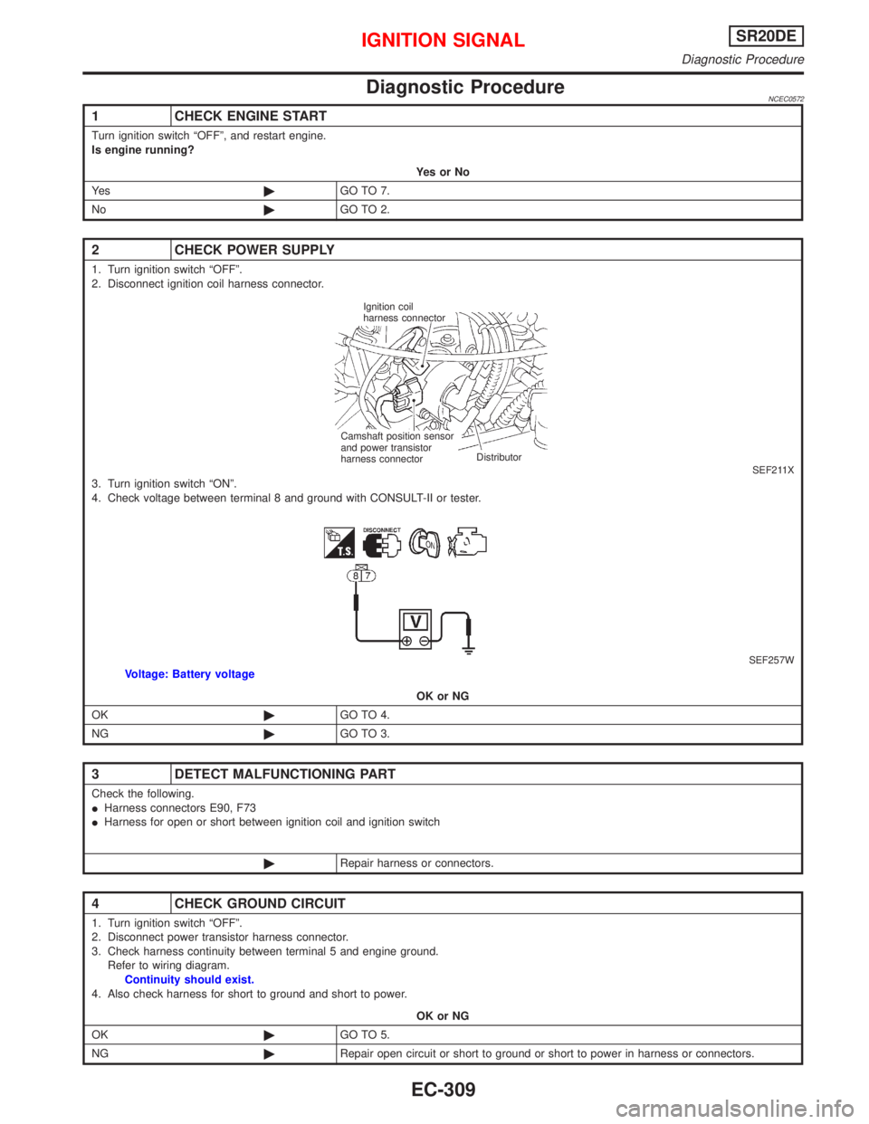
2 CHECK POWER SUPPLY
1. Turn ignition switch ªOFFº.
2. Disconnect ignition coil harness connector.
SEF211X3. Turn ignition switch ªONº.
4. Check voltage between terminal 8 and ground with CONSULT-II or tester.
SEF257WVoltage: Battery voltage
OK or NG
OK©GO TO 4.
NG©GO TO 3.
3 DETECT MALFUNCTIONING PART
Check the following.
IHarness connectors E90, F73
IHarness for open or short between ignition coil and ignition switch
©Repair harness or connectors.
4 CHECK GROUND CIRCUIT
1. Turn ignition switch ªOFFº.
2. Disconnect power transistor harness connector.
3. Check harness continuity between terminal 5 and engine ground.
Refer to wiring diagram.
Continuity should exist.
4. Also check harness for short to ground and short to power.
OK or NG
OK©GO TO 5.
NG©Repair open circuit or short to ground or short to power in harness or connectors.
Ignition coil
harness connector
Distributor Camshaft position sensor
and power transistor
harness connector
IGNITION SIGNALSR20DE
Diagnostic Procedure
EC-309
Page 1110 of 2267

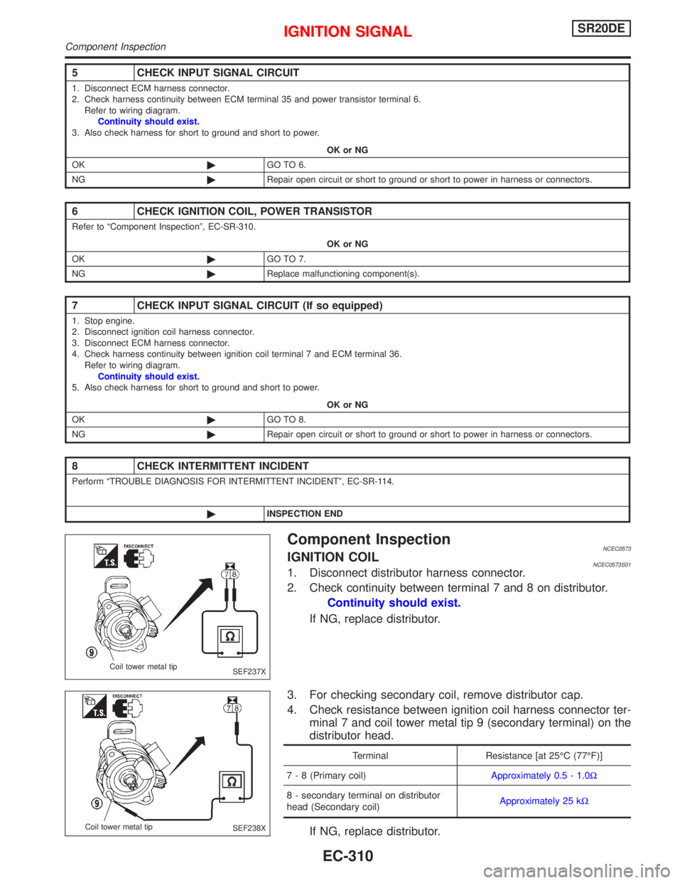
Component InspectionNCEC0573IGNITION COILNCEC0573S011. Disconnect distributor harness connector.
2. Check continuity between terminal 7 and 8 on distributor.
Continuity should exist.
If NG, replace distributor.
3. For checking secondary coil, remove distributor cap.
4. Check resistance between ignition coil harness connector ter-
minal 7 and coil tower metal tip 9 (secondary terminal) on the
distributor head.
Terminal Resistance [at 25ÉC (77ÉF)]
7 - 8 (Primary coil)Approximately 0.5 - 1.0W
8 - secondary terminal on distributor
head (Secondary coil)Approximately 25 kW
If NG, replace distributor.
5 CHECK INPUT SIGNAL CIRCUIT
1. Disconnect ECM harness connector.
2. Check harness continuity between ECM terminal 35 and power transistor terminal 6.
Refer to wiring diagram.
Continuity should exist.
3. Also check harness for short to ground and short to power.
OK or NG
OK©GO TO 6.
NG©Repair open circuit or short to ground or short to power in harness or connectors.
6 CHECK IGNITION COIL, POWER TRANSISTOR
Refer to ªComponent Inspectionº, EC-SR-310.
OK or NG
OK©GO TO 7.
NG©Replace malfunctioning component(s).
7 CHECK INPUT SIGNAL CIRCUIT (If so equipped)
1. Stop engine.
2. Disconnect ignition coil harness connector.
3. Disconnect ECM harness connector.
4. Check harness continuity between ignition coil terminal 7 and ECM terminal 36.
Refer to wiring diagram.
Continuity should exist.
5. Also check harness for short to ground and short to power.
OK or NG
OK©GO TO 8.
NG©Repair open circuit or short to ground or short to power in harness or connectors.
8 CHECK INTERMITTENT INCIDENT
Perform ªTROUBLE DIAGNOSIS FOR INTERMITTENT INCIDENTº, EC-SR-114.
©INSPECTION END
SEF237X Coil tower metal tip
SEF238X Coil tower metal tip
IGNITION SIGNALSR20DE
Component Inspection
EC-310
Page 1113 of 2267
Wiring DiagramNCEC0440
YEC252
BATTERY
Refer to EL-POWER.
Detectable line for DTC
Non-detectable line for DTC
Hyper CVT models
M/T models
FUSE
BLOCK
(J/B) IGNITION
SWITCH
ECM
.REFER TO THE FOLLOWING
M1FUSE BLOCK -
Junction Box (J/B)
E104FUSE BLOCK -
Junction Box (J/B)
OFF
ACC
ONST
START SIGNALSR20DE
Wiring Diagram
EC-313
Page 1117 of 2267
Wiring DiagramNCEC0447
YEC253
IGNITION SWITCH
ON or START
Refer to EL-POWER.
Detectable line for DTC
Non-detectable line for DTC
Hyper CVT models
M/T models FUSE
BLOCK
(J/B)
ECM
.REFER TO THE FOLLOWING
M1FUSE BLOCK -
Junction Box (J/B)
B8FUSE BLOCK -
Junction Box (J/B)
FUEL
PUMP
RELAY
FUEL PUMP
FUEL PUMPSR20DE
Wiring Diagram
EC-317
Page 1119 of 2267

3 DETECT MALFUNCTIONING PART
Check the following.
I15A fuse
IHarness for open or short between fuse and fuel pump relay
©Repair harness or connectors.
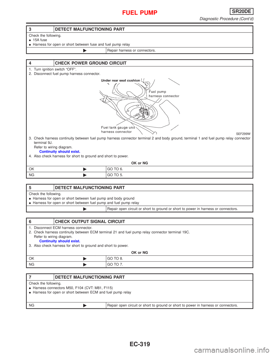
4 CHECK POWER GROUND CIRCUIT
1. Turn ignition switch ªOFFº.
2. Disconnect fuel pump harness connector.
SEF299W3. Check harness continuity between fuel pump harness connector terminal 2 and body ground, terminal 1 and fuel pump relay connector
terminal 9J.
Refer to wiring diagram.
Continuity should exist.
4. Also check harness for short to ground and short to power.
OK or NG
OK©GO TO 6.
NG©GO TO 5.
5 DETECT MALFUNCTIONING PART
Check the following.
IHarness for open or short between fuel pump and body ground
IHarness for open or short between fuel pump and fuel pump relay
©Repair open circuit or short to ground or short to power in harness or connectors.
6 CHECK OUTPUT SIGNAL CIRCUIT
1. Disconnect ECM harness connector.
2. Check harness continuity between ECM terminal 21 and fuel pump relay connector terminal 19C.
Refer to wiring diagram.
Continuity should exist.
3. Also check harness for short to ground and short to power.
OK or NG
OK©GO TO 8.
NG©GO TO 7.
7 DETECT MALFUNCTIONING PART
Check the following.
IHarness connectors M50, F104 (CVT: M81, F115)
IHarness for open or short between ECM and fuel pump relay
NG©Repair open circuit or short to ground or short to power in harness or connectors.
FUEL PUMPSR20DE
Diagnostic Procedure (Cont'd)
EC-319
Page 1122 of 2267
Wiring DiagramNCEC0450
YEC254
POWER STEERING OIL PRESSURE SWITCHSR20DE
Wiring Diagram
EC-322
Page 1124 of 2267

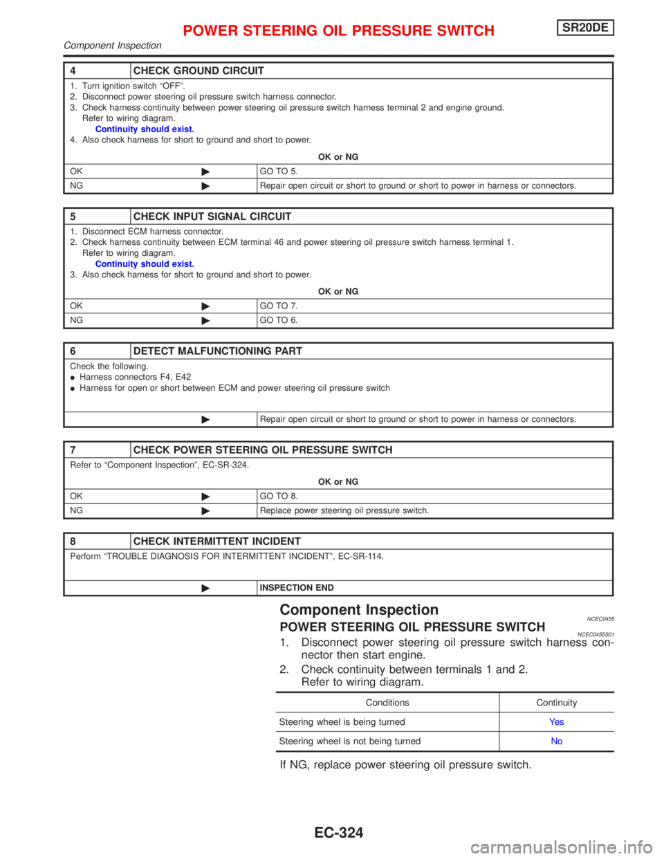
Component InspectionNCEC0455POWER STEERING OIL PRESSURE SWITCHNCEC0455S011. Disconnect power steering oil pressure switch harness con-
nector then start engine.
2. Check continuity between terminals 1 and 2.
Refer to wiring diagram.
Conditions Continuity
Steering wheel is being turnedYe s
Steering wheel is not being turnedNo
If NG, replace power steering oil pressure switch.
4 CHECK GROUND CIRCUIT
1. Turn ignition switch ªOFFº.
2. Disconnect power steering oil pressure switch harness connector.
3. Check harness continuity between power steering oil pressure switch harness terminal 2 and engine ground.
Refer to wiring diagram.
Continuity should exist.
4. Also check harness for short to ground and short to power.
OK or NG
OK©GO TO 5.
NG©Repair open circuit or short to ground or short to power in harness or connectors.
5 CHECK INPUT SIGNAL CIRCUIT
1. Disconnect ECM harness connector.
2. Check harness continuity between ECM terminal 46 and power steering oil pressure switch harness terminal 1.
Refer to wiring diagram.
Continuity should exist.
3. Also check harness for short to ground and short to power.
OK or NG
OK©GO TO 7.
NG©GO TO 6.
6 DETECT MALFUNCTIONING PART
Check the following.
IHarness connectors F4, E42
IHarness for open or short between ECM and power steering oil pressure switch
©Repair open circuit or short to ground or short to power in harness or connectors.
7 CHECK POWER STEERING OIL PRESSURE SWITCH
Refer to ªComponent Inspectionº, EC-SR-324.
OK or NG
OK©GO TO 8.
NG©Replace power steering oil pressure switch.
8 CHECK INTERMITTENT INCIDENT
Perform ªTROUBLE DIAGNOSIS FOR INTERMITTENT INCIDENTº, EC-SR-114.
©INSPECTION END
POWER STEERING OIL PRESSURE SWITCHSR20DE
Component Inspection
EC-324
Page 1126 of 2267
Wiring DiagramNCEC0550
YEC255
ELECTRICAL LOAD SIGNALSR20DE
Wiring Diagram
EC-326