Page 1057 of 2267
Wiring DiagramNCEC0277MODELS BEFORE VIN - P11U0548750
YEC844
IGNITION SWITCH
ON or START
Refer to EL-POWER.: Detectable line for DTC
: Non-detectable line for DTC
: Hyper CVT models
: M/T models FUSE
BLOCK
(J/B)
COMBINATION
METER
(SPEEDOMETER)
ECM
REFER TO THE FOLLOWING
FUSE BLOCK -
Junction Box (J/B) VEHICLE
SPEED
SENSOR BATTERY
DTC P0500 VEHICLE SPEED SENSOR (VSS)SR20DE
Wiring Diagram
EC-257
Page 1058 of 2267
MT MODELS WITH ABS AFTER VIN - P11U0548750
YEC091A
DTC P0500 VEHICLE SPEED SENSOR (VSS)SR20DE
Wiring Diagram (Cont'd)
EC-258
Page 1059 of 2267
EXCEPT MT MODELS WITH ABS AFTER VIN - P11U0548750
YEC092A
DTC P0500 VEHICLE SPEED SENSOR (VSS)SR20DE
Wiring Diagram (Cont'd)
EC-259
Page 1060 of 2267

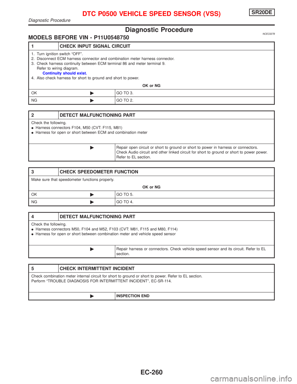
Diagnostic ProcedureNCEC0278MODELS BEFORE VIN - P11U0548750
1 CHECK INPUT SIGNAL CIRCUIT
1. Turn ignition switch ªOFFº.
2. Disconnect ECM harness connector and combination meter harness connector.
3. Check harness continuity between ECM terminal 86 and meter terminal 9.
Refer to wiring diagram.
Continuity should exist.
4. Also check harness for short to ground and short to power.
OK or NG
OK©GO TO 3.
NG©GO TO 2.
2 DETECT MALFUNCTIONING PART
Check the following.
IHarness connectors F104, M50 (CVT: F115, M81)
IHarness for open or short between ECM and combination meter
©Repair open circuit or short to ground or short to power in harness or connectors.
Check Audio circuit and other linked circuit for short to ground or short to power power.
Refer to EL section.
3 CHECK SPEEDOMETER FUNCTION
Make sure that speedometer functions properly.
OK or NG
OK©GO TO 5.
NG©GO TO 4.
4 DETECT MALFUNCTIONING PART
Check the following.
IHarness connectors M50, F104 and M52, F103 (CVT: M81, F115 and M80, F114)
IHarness for open or short between combination meter and vehicle speed sensor
©Repair harness or connectors. Check vehicle speed sensor and its circuit. Refer to EL
section.
5 CHECK INTERMITTENT INCIDENT
Check combination meter internal circuit for short to ground or short to power. Refer to EL section.
Perform ªTROUBLE DIAGNOSIS FOR INTERMITTENT INCIDENTº, EC-SR-114.
©INSPECTION END
DTC P0500 VEHICLE SPEED SENSOR (VSS)SR20DE
Diagnostic Procedure
EC-260
Page 1061 of 2267

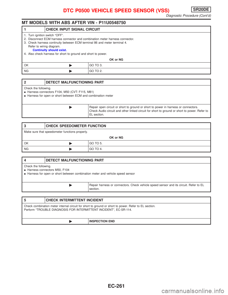
MT MODELS WITH ABS AFTER VIN - P11U0548750
1 CHECK INPUT SIGNAL CIRCUIT
1. Turn ignition switch ªOFFº.
2. Disconnect ECM harness connector and combination meter harness connector.
3. Check harness continuity between ECM terminal 86 and meter terminal 4.
Refer to wiring diagram.
Continuity should exist.
4. Also check harness for short to ground and short to power.
OK or NG
OK©GO TO 3.
NG©GO TO 2.
2 DETECT MALFUNCTIONING PART
Check the following.
IHarness connectors F104, M50 (CVT: F115, M81)
IHarness for open or short between ECM and combination meter
©Repair open circuit or short to ground or short to power in harness or connectors.
Check Audio circuit and other linked circuit for short to ground or short to power. Refer to
EL section.
3 CHECK SPEEDOMETER FUNCTION
Make sure that speedometer functions properly.
OK or NG
OK©GO TO 5.
NG©GO TO 4.
4 DETECT MALFUNCTIONING PART
Check the following.
IHarness connectors M50, F104
IHarness for open or short between combination meter and vehicle speed sensor
©Repair harness or connectors. Check vehicle speed sensor and its circuit. Refer to EL
section.
5 CHECK INTERMITTENT INCIDENT
Check combination meter internal circuit for short to ground or short to power. Refer to EL section.
Perform ªTROUBLE DIAGNOSIS FOR INTERMITTENT INCIDENTº, EC-SR-114.
©INSPECTION END
DTC P0500 VEHICLE SPEED SENSOR (VSS)SR20DE
Diagnostic Procedure (Cont'd)
EC-261
Page 1062 of 2267

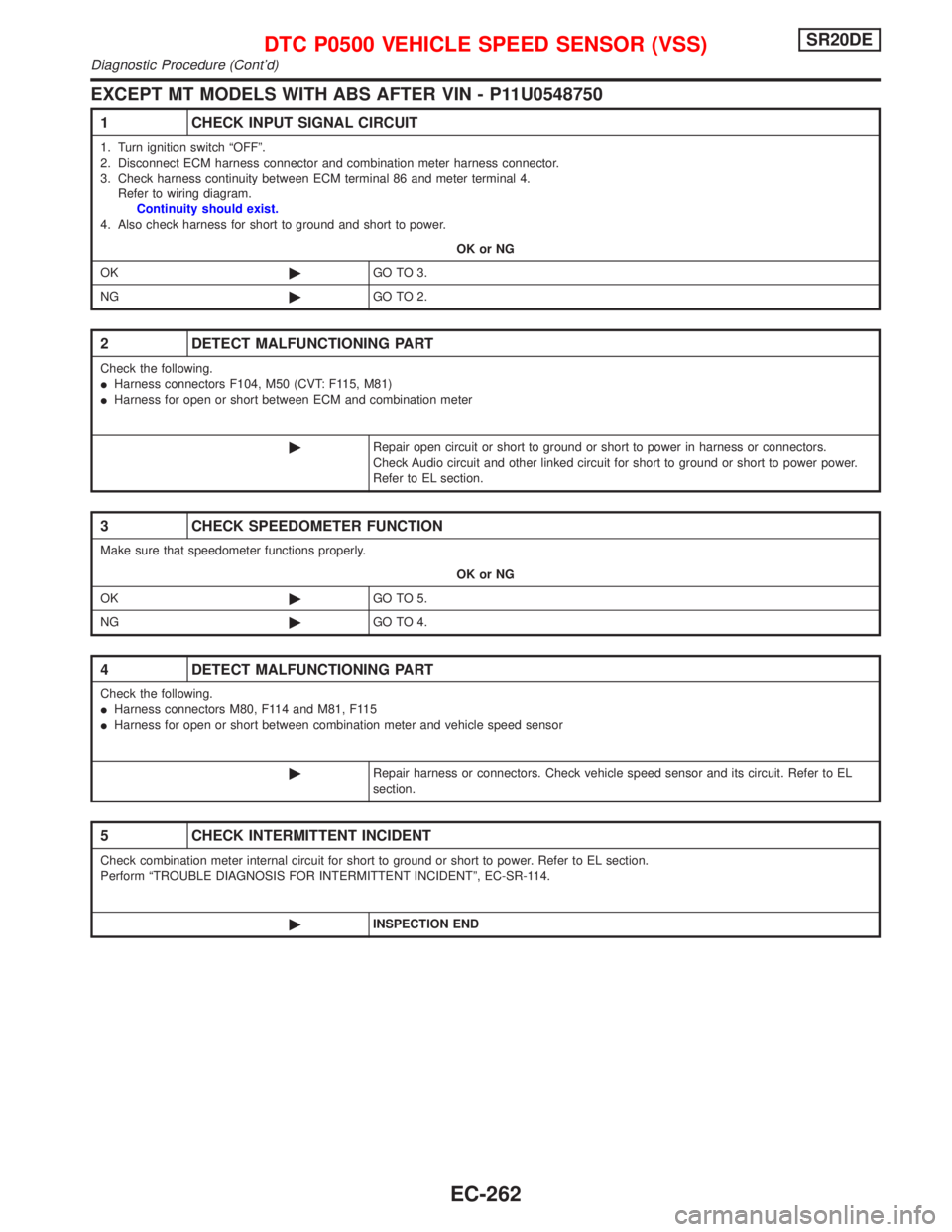
EXCEPT MT MODELS WITH ABS AFTER VIN - P11U0548750
1 CHECK INPUT SIGNAL CIRCUIT
1. Turn ignition switch ªOFFº.
2. Disconnect ECM harness connector and combination meter harness connector.
3. Check harness continuity between ECM terminal 86 and meter terminal 4.
Refer to wiring diagram.
Continuity should exist.
4. Also check harness for short to ground and short to power.
OK or NG
OK©GO TO 3.
NG©GO TO 2.
2 DETECT MALFUNCTIONING PART
Check the following.
IHarness connectors F104, M50 (CVT: F115, M81)
IHarness for open or short between ECM and combination meter
©Repair open circuit or short to ground or short to power in harness or connectors.
Check Audio circuit and other linked circuit for short to ground or short to power power.
Refer to EL section.
3 CHECK SPEEDOMETER FUNCTION
Make sure that speedometer functions properly.
OK or NG
OK©GO TO 5.
NG©GO TO 4.
4 DETECT MALFUNCTIONING PART
Check the following.
IHarness connectors M80, F114 and M81, F115
IHarness for open or short between combination meter and vehicle speed sensor
©Repair harness or connectors. Check vehicle speed sensor and its circuit. Refer to EL
section.
5 CHECK INTERMITTENT INCIDENT
Check combination meter internal circuit for short to ground or short to power. Refer to EL section.
Perform ªTROUBLE DIAGNOSIS FOR INTERMITTENT INCIDENTº, EC-SR-114.
©INSPECTION END
DTC P0500 VEHICLE SPEED SENSOR (VSS)SR20DE
Diagnostic Procedure (Cont'd)
EC-262
Page 1065 of 2267
Wiring DiagramNCEC0284
YEC845
: Detectable line for DTC
: Non-detectable line for DTC
ECM ECM
RELAYRefer to EL-POWER. BATTERY
IACV-AAC
VA LV E
DTC P0505 IDLE AIR CONTROL VALVE (IACV) Ð
AUXILIARY AIR CONTROL (AAC) VALVESR20DE
Wiring Diagram
EC-265
Page 1066 of 2267

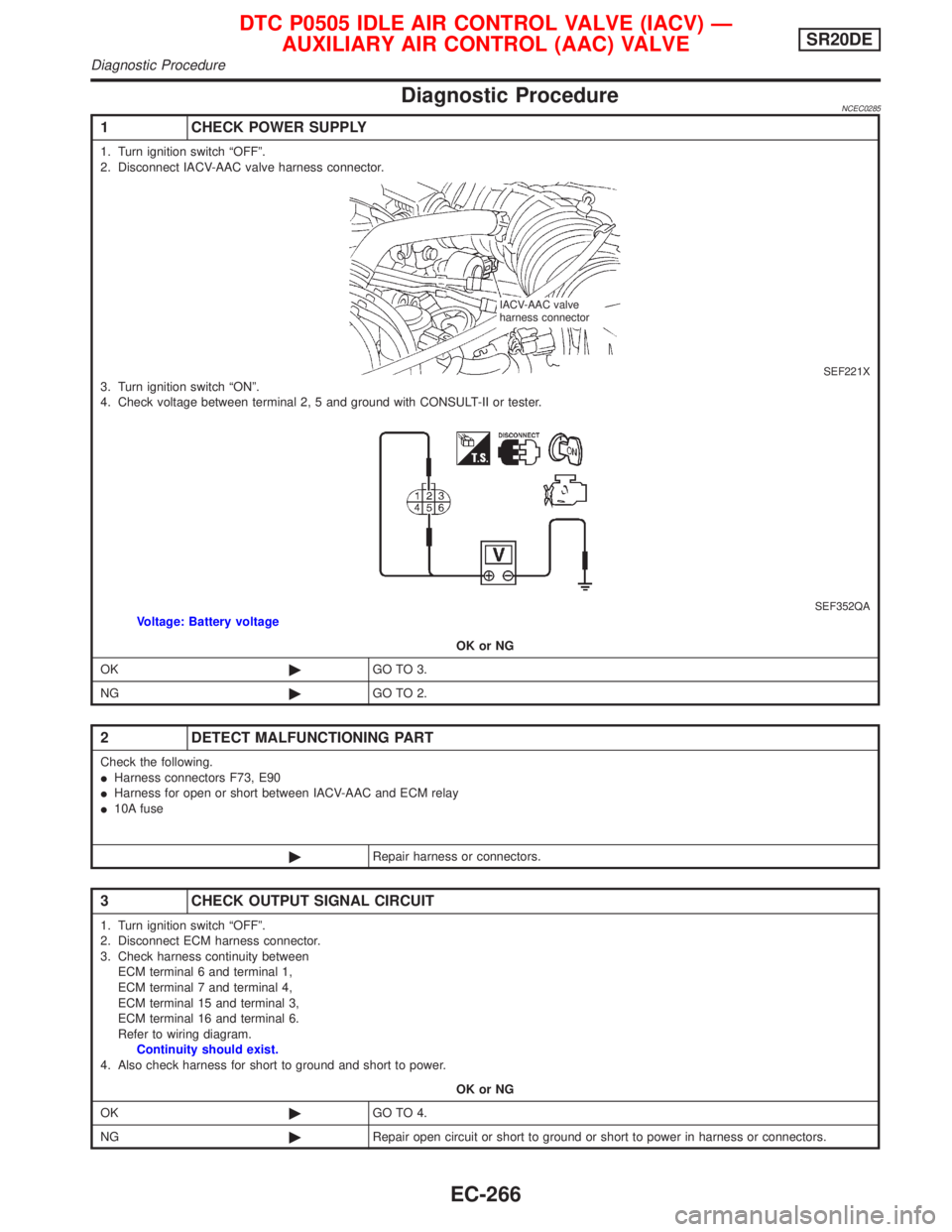
Diagnostic ProcedureNCEC0285
1 CHECK POWER SUPPLY
1. Turn ignition switch ªOFFº.
2. Disconnect IACV-AAC valve harness connector.
SEF221X3. Turn ignition switch ªONº.
4. Check voltage between terminal 2, 5 and ground with CONSULT-II or tester.
SEF352QAVoltage: Battery voltage
OK or NG
OK©GO TO 3.
NG©GO TO 2.
2 DETECT MALFUNCTIONING PART
Check the following.
IHarness connectors F73, E90
IHarness for open or short between IACV-AAC and ECM relay
I10A fuse
©Repair harness or connectors.
3 CHECK OUTPUT SIGNAL CIRCUIT
1. Turn ignition switch ªOFFº.
2. Disconnect ECM harness connector.
3. Check harness continuity between
ECM terminal 6 and terminal 1,
ECM terminal 7 and terminal 4,
ECM terminal 15 and terminal 3,
ECM terminal 16 and terminal 6.
Refer to wiring diagram.
Continuity should exist.
4. Also check harness for short to ground and short to power.
OK or NG
OK©GO TO 4.
NG©Repair open circuit or short to ground or short to power in harness or connectors.
IACV-AAC valve
harness connector
DTC P0505 IDLE AIR CONTROL VALVE (IACV) Ð
AUXILIARY AIR CONTROL (AAC) VALVESR20DE
Diagnostic Procedure
EC-266