Page 978 of 2267

Diagnostic ProcedureNCEC0142
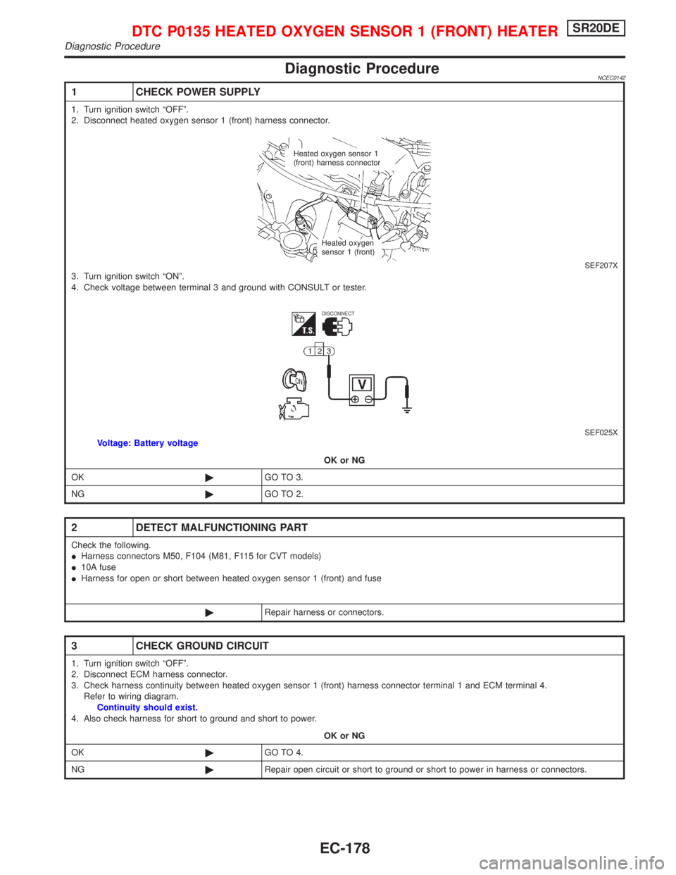
1 CHECK POWER SUPPLY
1. Turn ignition switch ªOFFº.
2. Disconnect heated oxygen sensor 1 (front) harness connector.
SEF207X3. Turn ignition switch ªONº.
4. Check voltage between terminal 3 and ground with CONSULT or tester.
SEF025XVoltage: Battery voltage
OK or NG
OK©GO TO 3.
NG©GO TO 2.
2 DETECT MALFUNCTIONING PART
Check the following.
IHarness connectors M50, F104 (M81, F115 for CVT models)
I10A fuse
IHarness for open or short between heated oxygen sensor 1 (front) and fuse
©Repair harness or connectors.
3 CHECK GROUND CIRCUIT
1. Turn ignition switch ªOFFº.
2. Disconnect ECM harness connector.
3. Check harness continuity between heated oxygen sensor 1 (front) harness connector terminal 1 and ECM terminal 4.
Refer to wiring diagram.
Continuity should exist.
4. Also check harness for short to ground and short to power.
OK or NG
OK©GO TO 4.
NG©Repair open circuit or short to ground or short to power in harness or connectors.
Heated oxygen sensor 1
(front) harness connector
Heated oxygen
sensor 1 (front)
DISCONNECT
DTC P0135 HEATED OXYGEN SENSOR 1 (FRONT) HEATERSR20DE
Diagnostic Procedure
EC-178
Page 983 of 2267
Wiring DiagramNCEC0150
YEC086A
DTC P0137 HEATED OXYGEN SENSOR 2
(REAR) (MIN. VOLTAGE MONITORING)SR20DE
Wiring Diagram
EC-183
Page 985 of 2267

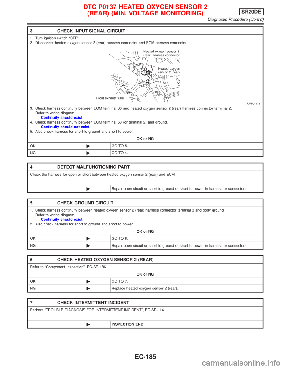
3 CHECK INPUT SIGNAL CIRCUIT
1. Turn ignition switch ªOFFº.
2. Disconnect heated oxygen sensor 2 (rear) harness connector and ECM harness connector.
SEF209X3. Check harness continuity between ECM terminal 63 and heated oxygen sensor 2 (rear) harness connector terminal 2.
Refer to wiring diagram.
Continuity should exist.
4. Check harness continuity between ECM terminal 63 (or terminal 2) and ground.
Continuity should not exist.
5. Also check harness for short to ground and short to power.
OK or NG
OK©GO TO 5.
NG©GO TO 4.
4 DETECT MALFUNCTIONING PART
Check the harness for open or short between heated oxygen sensor 2 (rear) and ECM.
©Repair open circuit or short to ground or short to power in harness or connectors.
5 CHECK GROUND CIRCUIT
1. Check harness continuity between heated oxygen sensor 2 (rear) harness connector terminal 3 and body ground.
Refer to wiring diagram.
Continuity should exist.
2. Also check harness for short to ground and short to power.
OK or NG
OK©GO TO 6.
NG©Repair open circuit or short to ground or short to power in harness or connectors.
6 CHECK HEATED OXYGEN SENSOR 2 (REAR)
Refer to ªComponent Inspectionº, EC-SR-186.
OK or NG
OK©GO TO 7.
NG©Replace heated oxygen sensor 2 (rear).
7 CHECK INTERMITTENT INCIDENT
Perform ªTROUBLE DIAGNOSIS FOR INTERMITTENT INCIDENTº, EC-SR-114.
©INSPECTION END
Heated oxygen sensor 2
(rear) harness connector
Heated oxygen
sensor 2 (rear)
Front exhaust tube
DTC P0137 HEATED OXYGEN SENSOR 2
(REAR) (MIN. VOLTAGE MONITORING)SR20DE
Diagnostic Procedure (Cont'd)
EC-185
Page 990 of 2267
Wiring DiagramNCEC0159
YEC086A
DTC P0138 HEATED OXYGEN SENSOR 2
(REAR) (MAX. VOLTAGE MONITORING)SR20DE
Wiring Diagram
EC-190
Page 992 of 2267

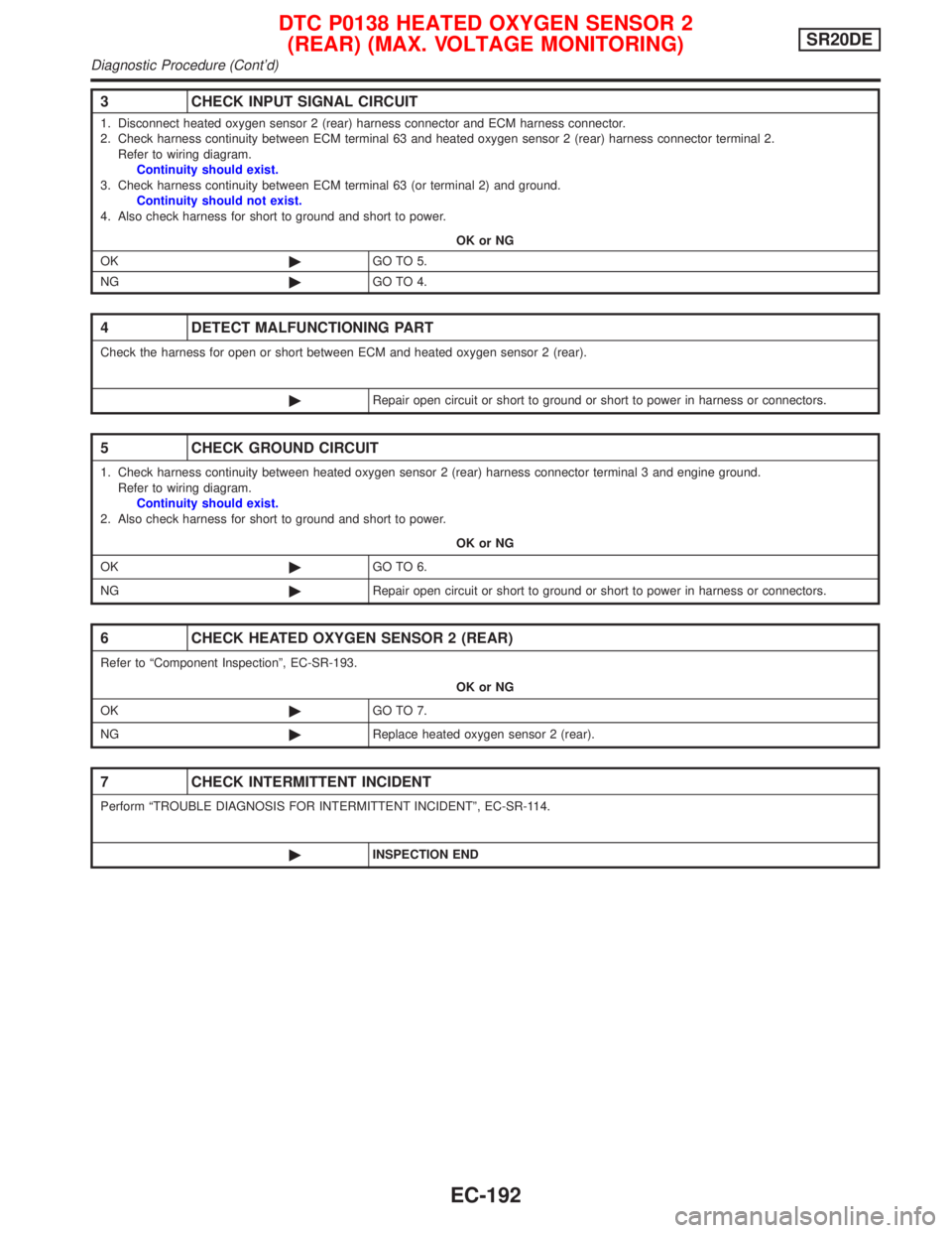
3 CHECK INPUT SIGNAL CIRCUIT
1. Disconnect heated oxygen sensor 2 (rear) harness connector and ECM harness connector.
2. Check harness continuity between ECM terminal 63 and heated oxygen sensor 2 (rear) harness connector terminal 2.
Refer to wiring diagram.
Continuity should exist.
3. Check harness continuity between ECM terminal 63 (or terminal 2) and ground.
Continuity should not exist.
4. Also check harness for short to ground and short to power.
OK or NG
OK©GO TO 5.
NG©GO TO 4.
4 DETECT MALFUNCTIONING PART
Check the harness for open or short between ECM and heated oxygen sensor 2 (rear).
©Repair open circuit or short to ground or short to power in harness or connectors.
5 CHECK GROUND CIRCUIT
1. Check harness continuity between heated oxygen sensor 2 (rear) harness connector terminal 3 and engine ground.
Refer to wiring diagram.
Continuity should exist.
2. Also check harness for short to ground and short to power.
OK or NG
OK©GO TO 6.
NG©Repair open circuit or short to ground or short to power in harness or connectors.
6 CHECK HEATED OXYGEN SENSOR 2 (REAR)
Refer to ªComponent Inspectionº, EC-SR-193.
OK or NG
OK©GO TO 7.
NG©Replace heated oxygen sensor 2 (rear).
7 CHECK INTERMITTENT INCIDENT
Perform ªTROUBLE DIAGNOSIS FOR INTERMITTENT INCIDENTº, EC-SR-114.
©INSPECTION END
DTC P0138 HEATED OXYGEN SENSOR 2
(REAR) (MAX. VOLTAGE MONITORING)SR20DE
Diagnostic Procedure (Cont'd)
EC-192
Page 997 of 2267
Wiring DiagramNCEC0168
YEC086A
DTC P0139 HEATED OXYGEN SENSOR 2
(REAR) (RESPONSE MONITORING)SR20DE
Wiring Diagram
EC-197
Page 999 of 2267

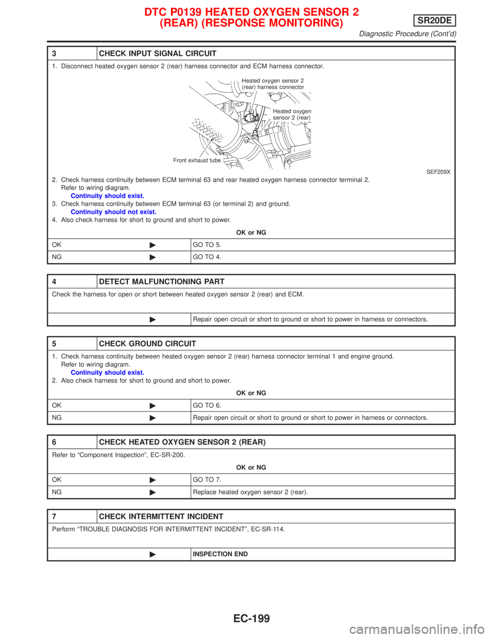
3 CHECK INPUT SIGNAL CIRCUIT
1. Disconnect heated oxygen sensor 2 (rear) harness connector and ECM harness connector.
SEF209X2. Check harness continuity between ECM terminal 63 and rear heated oxygen harness connector terminal 2.
Refer to wiring diagram.
Continuity should exist.
3. Check harness continuity between ECM terminal 63 (or terminal 2) and ground.
Continuity should not exist.
4. Also check harness for short to ground and short to power.
OK or NG
OK©GO TO 5.
NG©GO TO 4.
4 DETECT MALFUNCTIONING PART
Check the harness for open or short between heated oxygen sensor 2 (rear) and ECM.
©Repair open circuit or short to ground or short to power in harness or connectors.
5 CHECK GROUND CIRCUIT
1. Check harness continuity between heated oxygen sensor 2 (rear) harness connector terminal 1 and engine ground.
Refer to wiring diagram.
Continuity should exist.
2. Also check harness for short to ground and short to power.
OK or NG
OK©GO TO 6.
NG©Repair open circuit or short to ground or short to power in harness or connectors.
6 CHECK HEATED OXYGEN SENSOR 2 (REAR)
Refer to ªComponent Inspectionº, EC-SR-200.
OK or NG
OK©GO TO 7.
NG©Replace heated oxygen sensor 2 (rear).
7 CHECK INTERMITTENT INCIDENT
Perform ªTROUBLE DIAGNOSIS FOR INTERMITTENT INCIDENTº, EC-SR-114.
©INSPECTION END
Heated oxygen sensor 2
(rear) harness connector
Heated oxygen
sensor 2 (rear)
Front exhaust tube
DTC P0139 HEATED OXYGEN SENSOR 2
(REAR) (RESPONSE MONITORING)SR20DE
Diagnostic Procedure (Cont'd)
EC-199
Page 1003 of 2267
Wiring DiagramNCEC0177
YEC086A
DTC P0140 HEATED OXYGEN SENSOR 2
(REAR) (HIGH VOLTAGE)SR20DE
Wiring Diagram
EC-203