Page 947 of 2267
Wiring DiagramNCEC0100
YEC084A
DTC P0130 HEATED OXYGEN SENSOR 1
(FRONT) (CIRCUIT)SR20DE
Wiring Diagram
EC-147
Page 948 of 2267

Diagnostic ProcedureNCEC0101
1 INSPECTION START
1. Turn ignition switch ªOFFº.
2. Loosen and retighten engine ground screws.
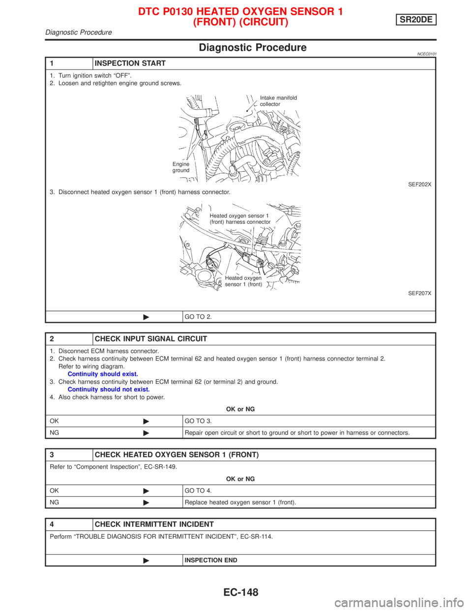
SEF202X3. Disconnect heated oxygen sensor 1 (front) harness connector.
SEF207X
©GO TO 2.
2 CHECK INPUT SIGNAL CIRCUIT
1. Disconnect ECM harness connector.
2. Check harness continuity between ECM terminal 62 and heated oxygen sensor 1 (front) harness connector terminal 2.
Refer to wiring diagram.
Continuity should exist.
3. Check harness continuity between ECM terminal 62 (or terminal 2) and ground.
Continuity should not exist.
4. Also check harness for short to power.
OK or NG
OK©GO TO 3.
NG©Repair open circuit or short to ground or short to power in harness or connectors.
3 CHECK HEATED OXYGEN SENSOR 1 (FRONT)
Refer to ªComponent Inspectionº, EC-SR-149.
OK or NG
OK©GO TO 4.
NG©Replace heated oxygen sensor 1 (front).
4 CHECK INTERMITTENT INCIDENT
Perform ªTROUBLE DIAGNOSIS FOR INTERMITTENT INCIDENTº, EC-SR-114.
©INSPECTION END
Intake manifold
collector
Engine
ground
Heated oxygen sensor 1
(front) harness connector
Heated oxygen
sensor 1 (front)
DTC P0130 HEATED OXYGEN SENSOR 1
(FRONT) (CIRCUIT)SR20DE
Diagnostic Procedure
EC-148
Page 954 of 2267

3 CHECK HEATED OXYGEN SENSOR 1 (FRONT) HEATER
Refer to ªComponent Inspectionº, EC-SR-179.
OK or NG
OK©GO TO 4.
NG©Replace heated oxygen sensor 1 (front).
4 CHECK HEATED OXYGEN SENSOR 1 (FRONT)
Refer to ªComponent Inspectionº, EC-SR-154.
OK or NG
OK©GO TO 5.
NG©Replace heated oxygen sensor 1 (front).
5 CHECK INTERMITTENT INCIDENT
Perform ªTROUBLE DIAGNOSIS FOR INTERMITTENT INCIDENTº, EC-SR-114.
Refer to ªWiring Diagramº, EC-SR-147, for circuit.
©INSPECTION END
Component InspectionNCEC0110HEATED OXYGEN SENSOR 1 (FRONT)NCEC0110S02With CONSULT-II
1) Start engine and warm it up to normal operating temperature.
2) Select ªMANU TRIGº and ªHI SPEEDº in ªDATA MONITORº
mode, and select ªHO2S1 (B1)º and ªHO2S1 MNTR (B1)º.
3) Hold engine speed at 2,000 rpm under no load during the fol-
lowing steps.
4) Touch ªRECORDº on CONSULT-II screen.
5) Check the following.
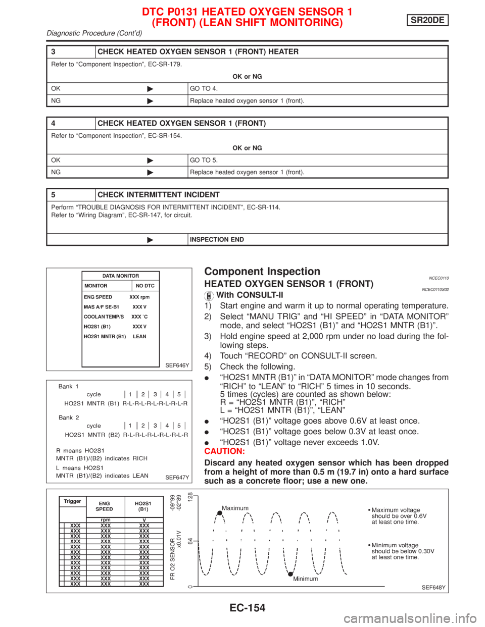
IªHO2S1 MNTR (B1)º in ªDATA MONITORº mode changes from
ªRICHº to ªLEANº to ªRICHº 5 times in 10 seconds.
5 times (cycles) are counted as shown below:
R = ªHO2S1 MNTR (B1)º, ªRICHº
L = ªHO2S1 MNTR (B1)º, ªLEANº
IªHO2S1 (B1)º voltage goes above 0.6V at least once.
IªHO2S1 (B1)º voltage goes below 0.3V at least once.
IªHO2S1 (B1)º voltage never exceeds 1.0V.
CAUTION:
Discard any heated oxygen sensor which has been dropped
from a height of more than 0.5 m (19.7 in) onto a hard surface
such as a concrete floor; use a new one.
SEF646Y
SEF647Y
SEF648Y
FR O2 SENSOR
x0.01V-09²99
-02²89
DTC P0131 HEATED OXYGEN SENSOR 1
(FRONT) (LEAN SHIFT MONITORING)SR20DE
Diagnostic Procedure (Cont'd)
EC-154
Page 960 of 2267

3 CHECK HARNESS CONNECTOR
1. Turn ignition switch ªOFFº.
2. Disconnect heated oxygen sensor 1 (front) harness connector.
3. Check harness connector for water.
Water should not exit.
OK or NG
OK©GO TO 4.
NG©Repair or replace harness connector.
4 CHECK HEATED OXYGEN SENSOR 1 (FRONT) HEATER
Refer to ªComponent Inspectionº, EC-SR-179.
OK or NG
OK©GO TO 5.
NG©Replace heated oxygen sensor 1 (front).
5 CHECK HEATED OXYGEN SENSOR 1 (FRONT)
Refer to ªComponent Inspectionº, EC-SR-160.
OK or NG
OK©GO TO 6.
NG©Replace heated oxygen sensor 1 (front).
6 CHECK INTERMITTENT INCIDENT
Perform ªTROUBLE DIAGNOSIS FOR INTERMITTENT INCIDENTº, EC-SR-114.
Refer to ªWiring Diagramº, EC-SR-147, for circuit.
©INSPECTION END
Component InspectionNCEC0118HEATED OXYGEN SENSOR 1 (FRONT)NCEC0118S02With CONSULT-II
1) Start engine and warm it up to normal operating temperature.
2) Select ªMANU TRIGº and ªHI SPEEDº in ªDATA MONITORº
mode, and select ªHO2S1 (B1)º and ªHO2S1 MNTR (B1)º.
3) Hold engine speed at 2,000 rpm under no load during the fol-
lowing steps.
4) Touch ªRECORDº on CONSULT-II screen.
5) Check the following.
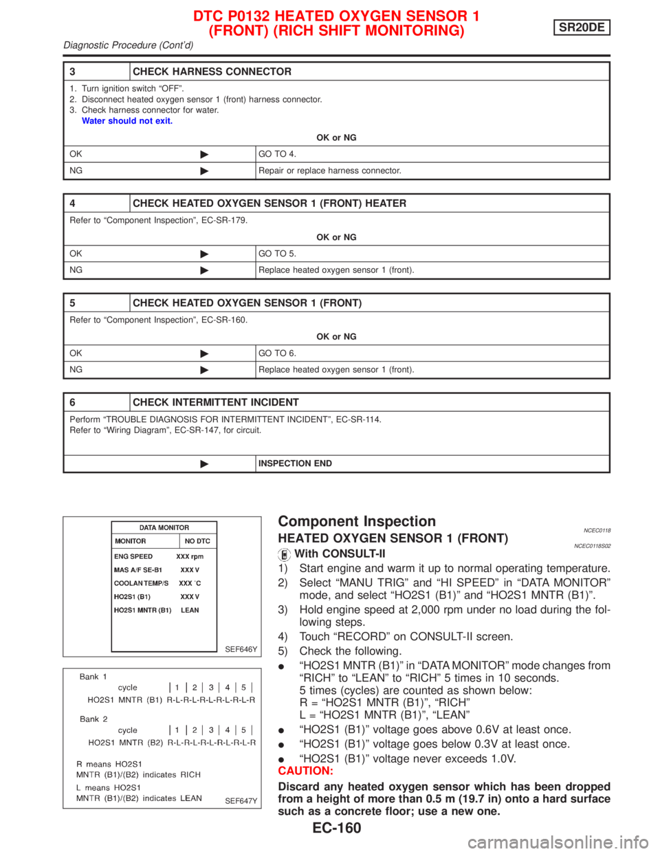
IªHO2S1 MNTR (B1)º in ªDATA MONITORº mode changes from
ªRICHº to ªLEANº to ªRICHº 5 times in 10 seconds.
5 times (cycles) are counted as shown below:
R = ªHO2S1 MNTR (B1)º, ªRICHº
L = ªHO2S1 MNTR (B1)º, ªLEANº
IªHO2S1 (B1)º voltage goes above 0.6V at least once.
IªHO2S1 (B1)º voltage goes below 0.3V at least once.
IªHO2S1 (B1)º voltage never exceeds 1.0V.
CAUTION:
Discard any heated oxygen sensor which has been dropped
from a height of more than 0.5 m (19.7 in) onto a hard surface
such as a concrete floor; use a new one.
SEF646Y
SEF647Y
DTC P0132 HEATED OXYGEN SENSOR 1
(FRONT) (RICH SHIFT MONITORING)SR20DE
Diagnostic Procedure (Cont'd)
EC-160
Page 965 of 2267
Wiring DiagramNCEC0125
YEC084A
DTC P0133 HEATED OXYGEN SENSOR 1
(FRONT) (RESPONSE MONITORING)SR20DE
Wiring Diagram
EC-165
Page 972 of 2267
Wiring DiagramNCEC0133
YEC084A
DTC P0134 HEATED OXYGEN SENSOR 1
(FRONT) (HIGH VOLTAGE)SR20DE
Wiring Diagram
EC-172
Page 973 of 2267

Diagnostic ProcedureNCEC0134
1 RETIGHTEN HEATED OXYGEN SENSOR 1 (FRONT)
Loosen and retighten heated oxygen sensor 1 (front).
Tightening torque:
40-60N×m (4.1 - 6.1 kg-m, 30 - 44 ft-lb)
©GO TO 2.
2 CHECK INPUT SIGNAL CIRCUIT
1. Disconnect heated oxygen sensor 1 (front) harness connector and ECM harness connector.
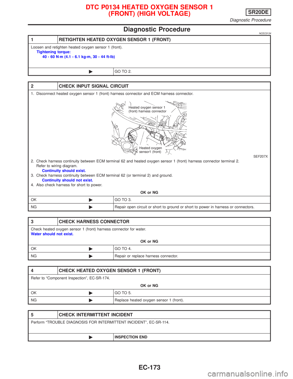
SEF207X2. Check harness continuity between ECM terminal 62 and heated oxygen sensor 1 (front) harness connector terminal 2.
Refer to wiring diagram.
Continuity should exist.
3. Check harness continuity between ECM terminal 62 (or terminal 2) and ground.
Continuity should not exist.
4. Also check harness for short to power.
OK or NG
OK©GO TO 3.
NG©Repair open circuit or short to ground or short to power in harness or connectors.
3 CHECK HARNESS CONNECTOR
Check heated oxygen sensor 1 (front) harness connector for water.
Water should not exist.
OK or NG
OK©GO TO 4.
NG©Repair or replace harness connector.
4 CHECK HEATED OXYGEN SENSOR 1 (FRONT)
Refer to ªComponent Inspectionº, EC-SR-174.
OK or NG
OK©GO TO 5.
NG©Replace heated oxygen sensor 1 (front).
5 CHECK INTERMITTENT INCIDENT
Perform ªTROUBLE DIAGNOSIS FOR INTERMITTENT INCIDENTº, EC-SR-114.
©INSPECTION END
Heated oxygen sensor 1
(front) harness connector
Heated oxygen
sensor1 (front)
DTC P0134 HEATED OXYGEN SENSOR 1
(FRONT) (HIGH VOLTAGE)SR20DE
Diagnostic Procedure
EC-173
Page 977 of 2267
Wiring DiagramNCEC0141
YEC085A
DTC P0135 HEATED OXYGEN SENSOR 1 (FRONT) HEATERSR20DE
Wiring Diagram
EC-177