Page 1073 of 2267
Wiring DiagramNCEC0292
YEC846
BATTERY
Refer to
EL-POWER.: Detectable line for DTC
: Non-detectable line for DTC
ECM
RELAY
OFF
CLOSEDWIDE
OPEN
OFFTHROTTLE
POSITION
SWITCH
(CLOSED THROTTLE POSITION
SWITCH AND WIDE OPEN
THROTTLE POSITION SWITCH
ECM
DTC P0510 CLOSED THROTTLE POSITION SWITCH
(IF SO EQUIPPED)SR20DE
Wiring Diagram
EC-273
Page 1074 of 2267

Diagnostic ProcedureNCEC0293
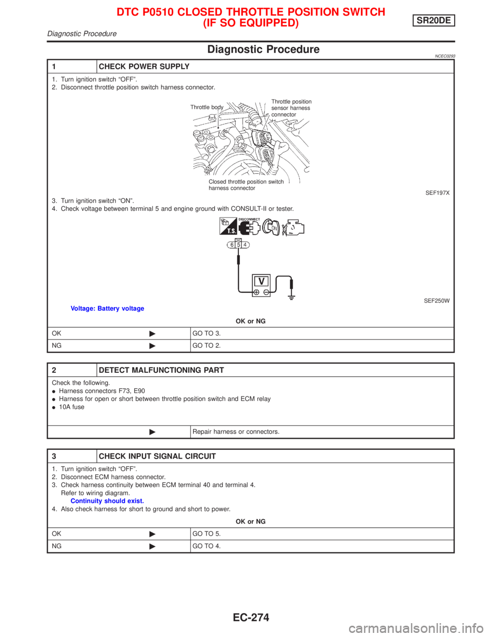
1 CHECK POWER SUPPLY
1. Turn ignition switch ªOFFº.
2. Disconnect throttle position switch harness connector.
SEF197X3. Turn ignition switch ªONº.
4. Check voltage between terminal 5 and engine ground with CONSULT-II or tester.
SEF250WVoltage: Battery voltage
OK or NG
OK©GO TO 3.
NG©GO TO 2.
2 DETECT MALFUNCTIONING PART
Check the following.
IHarness connectors F73, E90
IHarness for open or short between throttle position switch and ECM relay
I10A fuse
©Repair harness or connectors.
3 CHECK INPUT SIGNAL CIRCUIT
1. Turn ignition switch ªOFFº.
2. Disconnect ECM harness connector.
3. Check harness continuity between ECM terminal 40 and terminal 4.
Refer to wiring diagram.
Continuity should exist.
4. Also check harness for short to ground and short to power.
OK or NG
OK©GO TO 5.
NG©GO TO 4.
Throttle bodyThrottle position
sensor harness
connector
Closed throttle position switch
harness connector
DTC P0510 CLOSED THROTTLE POSITION SWITCH
(IF SO EQUIPPED)SR20DE
Diagnostic Procedure
EC-274
Page 1076 of 2267

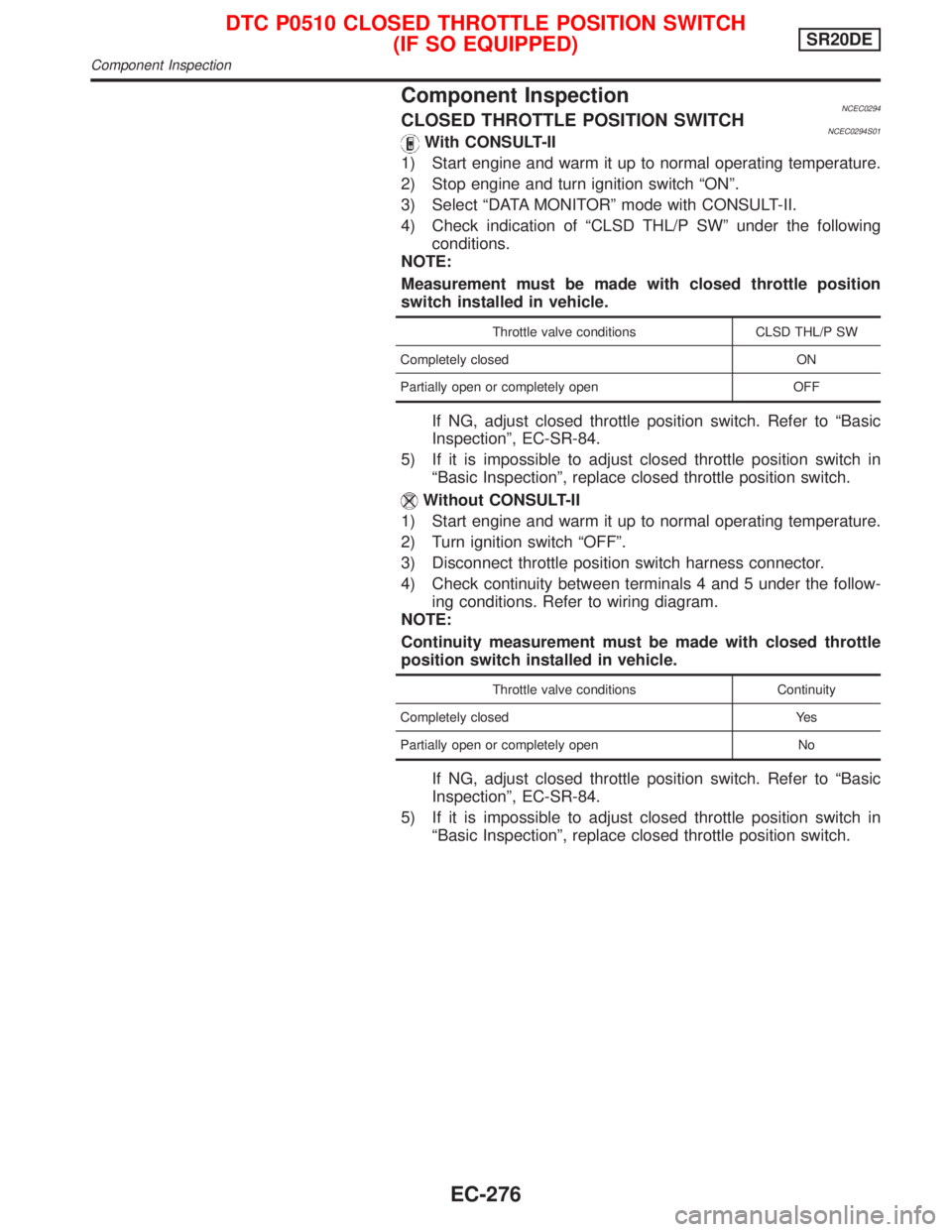
Component InspectionNCEC0294CLOSED THROTTLE POSITION SWITCHNCEC0294S01With CONSULT-II
1) Start engine and warm it up to normal operating temperature.
2) Stop engine and turn ignition switch ªONº.
3) Select ªDATA MONITORº mode with CONSULT-II.
4) Check indication of ªCLSD THL/P SWº under the following
conditions.
NOTE:
Measurement must be made with closed throttle position
switch installed in vehicle.
Throttle valve conditions CLSD THL/P SW
Completely closed ON
Partially open or completely open OFF
If NG, adjust closed throttle position switch. Refer to ªBasic
Inspectionº, EC-SR-84.
5) If it is impossible to adjust closed throttle position switch in
ªBasic Inspectionº, replace closed throttle position switch.
Without CONSULT-II
1) Start engine and warm it up to normal operating temperature.
2) Turn ignition switch ªOFFº.
3) Disconnect throttle position switch harness connector.
4) Check continuity between terminals 4 and 5 under the follow-
ing conditions. Refer to wiring diagram.
NOTE:
Continuity measurement must be made with closed throttle
position switch installed in vehicle.
Throttle valve conditions Continuity
Completely closed Yes
Partially open or completely open No
If NG, adjust closed throttle position switch. Refer to ªBasic
Inspectionº, EC-SR-84.
5) If it is impossible to adjust closed throttle position switch in
ªBasic Inspectionº, replace closed throttle position switch.
DTC P0510 CLOSED THROTTLE POSITION SWITCH
(IF SO EQUIPPED)SR20DE
Component Inspection
EC-276
Page 1082 of 2267
Wiring DiagramNCEC0490
YEC847
Detectable line for DTC
Non-detectable line for DTC
COOLING
FA N
RELAY FUSE
BLOCK
(J/B)
COOLING
FA N
MOTOR-2 Refer to EL-POWER. BATTERY
COOLING
FA N
MOTOR-1 IGNITION SWITCH
ON or START
REFER TO THE FOLLOWING
FUSE BLOCK -
Junction Box (J/B)
DTC P1217 OVERHEAT (COOLING SYSTEM)SR20DE
Wiring Diagram
EC-282
Page 1083 of 2267
YEC848
: Detectable line for DTC
: Non-detectable line for DTC
: Hyper CVT models REFRIGERANT
SENSOR
TCM
(TRANSMISSION
CONTROL
MODULE) ECM
DTC P1217 OVERHEAT (COOLING SYSTEM)SR20DE
Wiring Diagram (Cont'd)
EC-283
Page 1085 of 2267

4 DETECT MALFUNCTIONING PART
Check the following.
IHarness connectors M70, E125
I10A fuse
I40A fusible link
IHarness for open or short between cooling fan relay and fuse
©Repair open circuit or short to ground or short to power in harness or connectors.
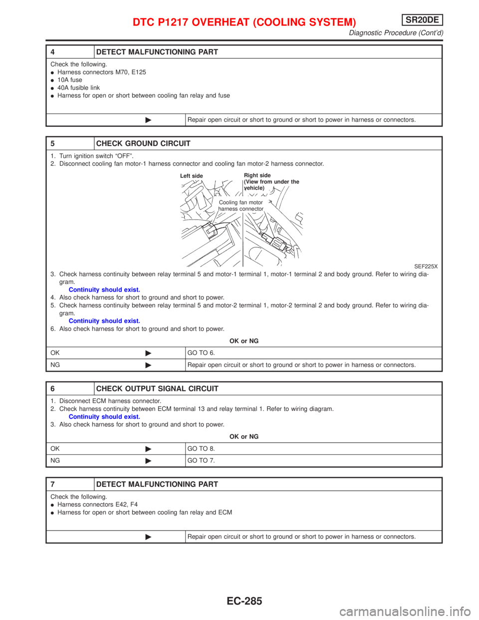
5 CHECK GROUND CIRCUIT
1. Turn ignition switch ªOFFº.
2. Disconnect cooling fan motor-1 harness connector and cooling fan motor-2 harness connector.
SEF225X3. Check harness continuity between relay terminal 5 and motor-1 terminal 1, motor-1 terminal 2 and body ground. Refer to wiring dia-
gram.
Continuity should exist.
4. Also check harness for short to ground and short to power.
5. Check harness continuity between relay terminal 5 and motor-2 terminal 1, motor-2 terminal 2 and body ground. Refer to wiring dia-
gram.
Continuity should exist.
6. Also check harness for short to ground and short to power.
OK or NG
OK©GO TO 6.
NG©Repair open circuit or short to ground or short to power in harness or connectors.
6 CHECK OUTPUT SIGNAL CIRCUIT
1. Disconnect ECM harness connector.
2. Check harness continuity between ECM terminal 13 and relay terminal 1. Refer to wiring diagram.
Continuity should exist.
3. Also check harness for short to ground and short to power.
OK or NG
OK©GO TO 8.
NG©GO TO 7.
7 DETECT MALFUNCTIONING PART
Check the following.
IHarness connectors E42, F4
IHarness for open or short between cooling fan relay and ECM
©Repair open circuit or short to ground or short to power in harness or connectors.
Cooling fan motor
harness connector Left sideRight side
(View from under the
vehicle)
DTC P1217 OVERHEAT (COOLING SYSTEM)SR20DE
Diagnostic Procedure (Cont'd)
EC-285
Page 1089 of 2267

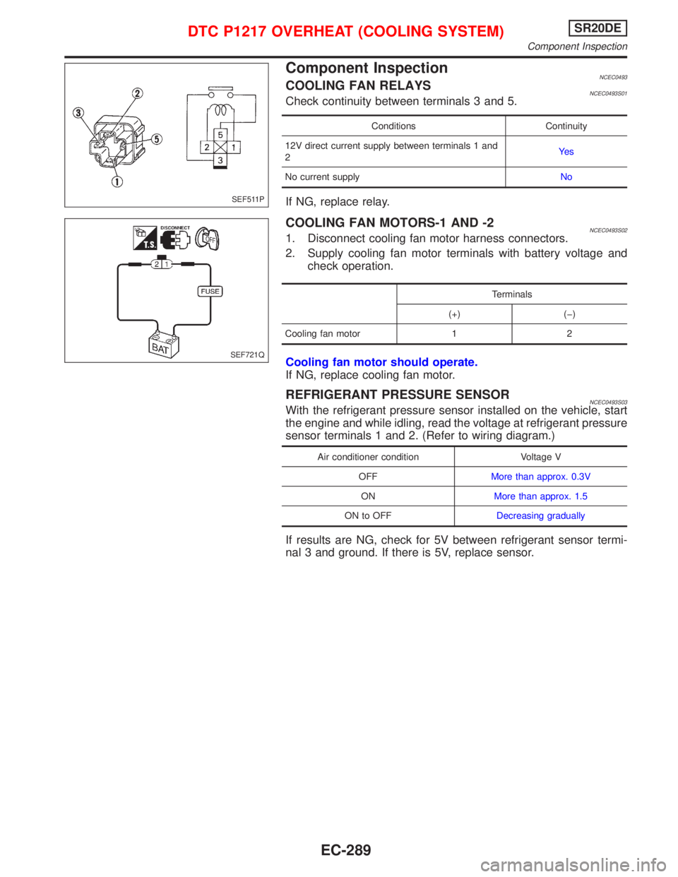
Component InspectionNCEC0493COOLING FAN RELAYSNCEC0493S01Check continuity between terminals 3 and 5.
Conditions Continuity
12V direct current supply between terminals 1 and
2Ye s
No current supplyNo
If NG, replace relay.
COOLING FAN MOTORS-1 AND -2NCEC0493S021. Disconnect cooling fan motor harness connectors.
2. Supply cooling fan motor terminals with battery voltage and
check operation.
Terminals
(+) (þ)
Cooling fan motor 1 2
Cooling fan motor should operate.
If NG, replace cooling fan motor.
REFRIGERANT PRESSURE SENSORNCEC0493S03With the refrigerant pressure sensor installed on the vehicle, start
the engine and while idling, read the voltage at refrigerant pressure
sensor terminals 1 and 2. (Refer to wiring diagram.)
Air conditioner condition Voltage V
OFFMore than approx. 0.3V
ONMore than approx. 1.5
ON to OFFDecreasing gradually
If results are NG, check for 5V between refrigerant sensor termi-
nal 3 and ground. If there is 5V, replace sensor.
SEF511P
SEF721Q
DTC P1217 OVERHEAT (COOLING SYSTEM)SR20DE
Component Inspection
EC-289
Page 1092 of 2267
Wiring DiagramNCEC0331
YEC839
: Detectable line for DTC
: Non-detectable line for DTC
: Hyper CVT models
ECMTCM
(TRANSMISSION
CONTROL
MODULE) CRANKSHAFT
POSITION
SENSOR (OBD)
DTC P1336 CRANKSHAFT POSITION SENSOR
(CKPS) (OBD) (COG)SR20DE
Wiring Diagram
EC-292