Page 672 of 2267
Diagnostic ProcedureNCEC0211
1 RETIGHTEN GROUND SCREWS
Loosen and retighten engine ground screws.
SEF994W
©GO TO 2.
2 CHECK INPUT SIGNAL CIRCUIT-1
1. Turn ignition switch ªOFFº.
2. Disconnect ECM harness connector and knock sensor harness connector.
SEF056X3. Check harness continuity between knock sensor signal terminal 2 and ECM terminal 81.
Refer to wiring diagram.
Continuity should exist.
4. Also check harness for short to ground and short to power.
OK or NG
OK©GO TO 4.
NG©GO TO 3.
3 DETECT MALFUNCTIONING PART
Check the harness for open or short between knock sensor and ECM.
©Repair open circuit or short to ground or short to power in harness or connectors.
4 CHECK KNOCK SENSOR
Knock sensor
Refer to ªComponent Inspectionº, EC-QG-231.
OK or NG
OK©GO TO 5.
NG©Replace knock sensor.
View from the underside of the vehicle
Knock sensor
harness
connector
Oil filter
DTC P0325 KNOCK SENSOR (KS)QG16I18DE
Diagnostic Procedure
EC-230
Page 821 of 2267
Vacuum Hose DrawingNCEC0012Refer to ªSystem Diagramº on EC-SR-20 for vacuum control system.
NOTE:
Do not use soapy water or any type of solvent while installing vacuum hoses or purge hoses.
SEF191X Intake manifold collector
Throttle body
Rear view (Left side)Rear view (Right side)
Intake manifold collector
Fuel pressure
regulator
To brake
booster
Air hose to
power steering
air valve
EVAP purge line to engine
Fuel filter
To EVAP
canister
(RHD models)
EVAP purge volume
control solenoid valve
To EVAP
canister
(LHD models)
Front view
EVAP purge
line to
engine
EVAP canister
(LHD models)
Power steering air valve
To intake manifold
collector
Air tube for power
steering air valve
To EVAP
canister
(RHD models)
ENGINE AND EMISSION CONTROL OVERALL SYSTEMSR20DE
Vacuum Hose Drawing
EC-21
Page 829 of 2267
EVAPORATIVE EMISSION LINE DRAWINGNCEC0020NOTE:
Do not use soapy water or any type of solvent while installing
vacuum hoses or purge hoses.
SEF193X Intake manifold collector
Throttle body
Rear view (Left side)Rear view (Right side)
Intake manifold collector
Fuel pressure
regulator
To brake
booster
Air hose to
power steering
air valve
EVAP purge line to engine
Fuel filter
To EVAP
canister
(RHD models)
EVAP purge volume
control solenoid valve
To EVAP
canister
(LHD models)
Front view
EVAP purge
line to
engine
EVAP canister
(LHD models)
Power steering air valve
To intake manifold
collector
Air tube for power
steering air valve
To EVAP
canister
(RHD models)
ENGINE AND EMISSION BASIC CONTROL
SYSTEM DESCRIPTIONSR20DE
Evaporative Emission System (Cont'd)
EC-29
Page 1015 of 2267

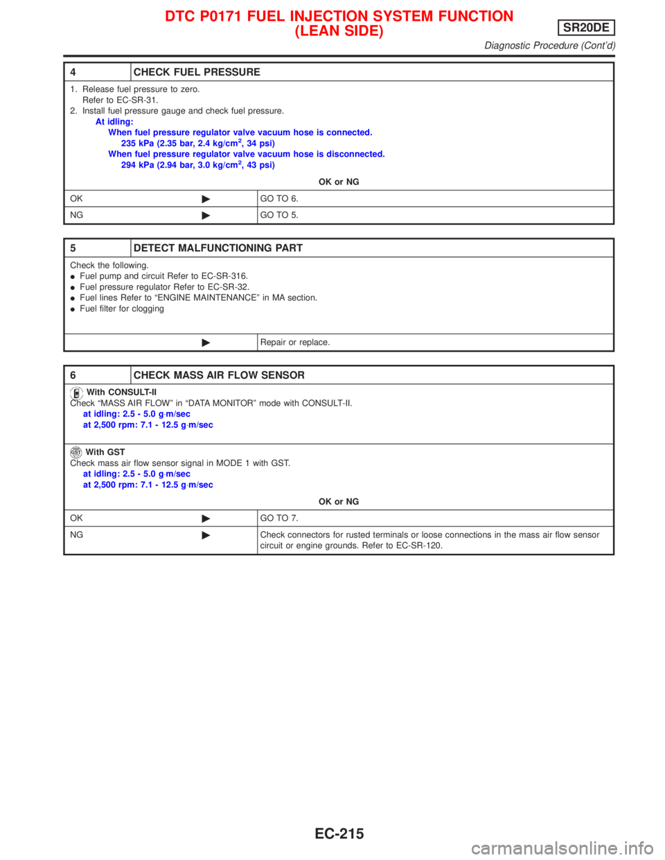
4 CHECK FUEL PRESSURE
1. Release fuel pressure to zero.
Refer to EC-SR-31.
2. Install fuel pressure gauge and check fuel pressure.
At idling:
When fuel pressure regulator valve vacuum hose is connected.
235 kPa (2.35 bar, 2.4 kg/cm
2, 34 psi)
When fuel pressure regulator valve vacuum hose is disconnected.
294 kPa (2.94 bar, 3.0 kg/cm
2, 43 psi)
OK or NG
OK©GO TO 6.
NG©GO TO 5.
5 DETECT MALFUNCTIONING PART
Check the following.
IFuel pump and circuit Refer to EC-SR-316.
IFuel pressure regulator Refer to EC-SR-32.
IFuel lines Refer to ªENGINE MAINTENANCEº in MA section.
IFuel filter for clogging
©Repair or replace.
6 CHECK MASS AIR FLOW SENSOR
With CONSULT-II
Check ªMASS AIR FLOWº in ªDATA MONITORº mode with CONSULT-II.
at idling: 2.5 - 5.0 g×m/sec
at 2,500 rpm: 7.1 - 12.5 g×m/sec
With GST
Check mass air flow sensor signal in MODE 1 with GST.
at idling: 2.5 - 5.0 g×m/sec
at 2,500 rpm: 7.1 - 12.5 g×m/sec
OK or NG
OK©GO TO 7.
NG©Check connectors for rusted terminals or loose connections in the mass air flow sensor
circuit or engine grounds. Refer to EC-SR-120.
DTC P0171 FUEL INJECTION SYSTEM FUNCTION
(LEAN SIDE)SR20DE
Diagnostic Procedure (Cont'd)
EC-215
Page 1027 of 2267

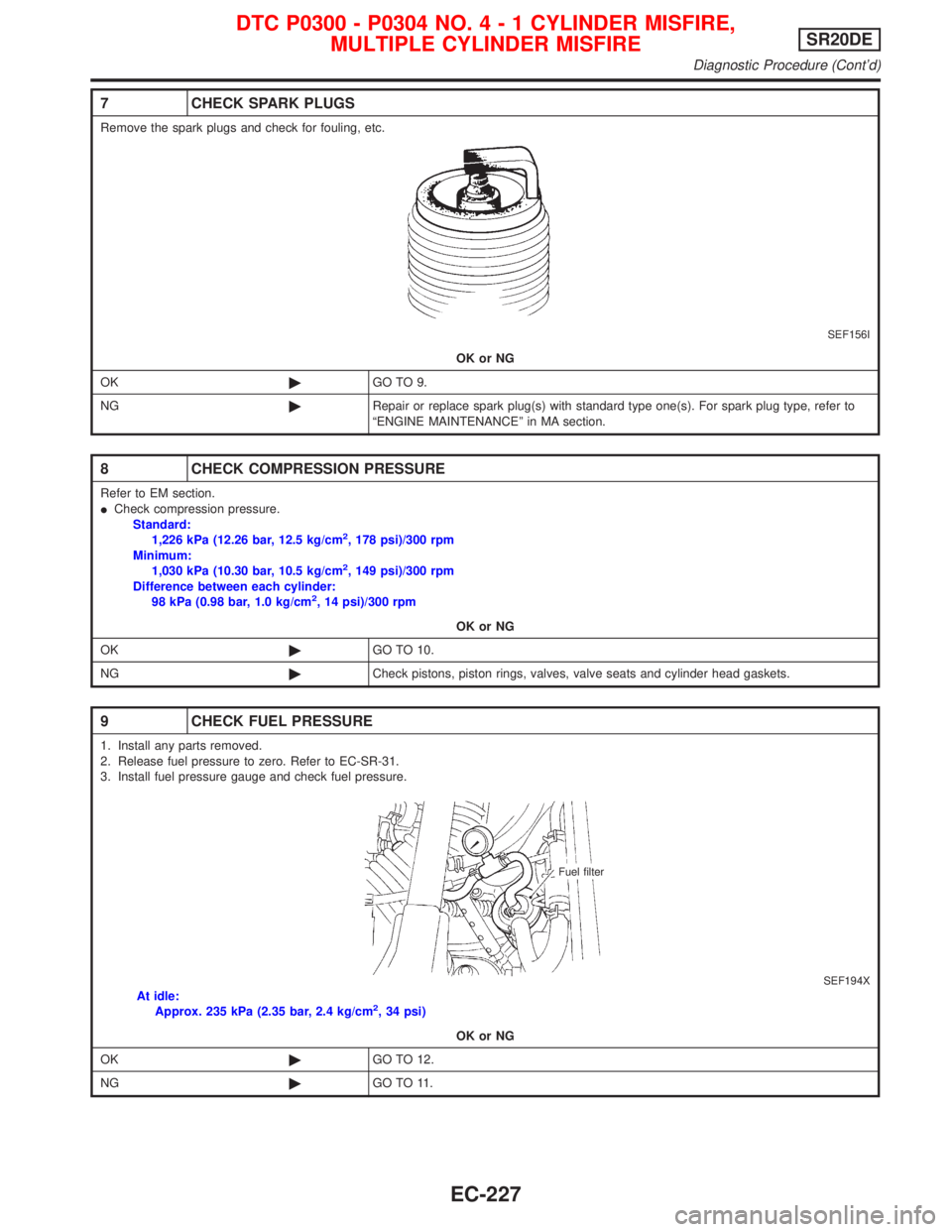
7 CHECK SPARK PLUGS
Remove the spark plugs and check for fouling, etc.
SEF156I
OK or NG
OK©GO TO 9.
NG©Repair or replace spark plug(s) with standard type one(s). For spark plug type, refer to
ªENGINE MAINTENANCEº in MA section.
8 CHECK COMPRESSION PRESSURE
Refer to EM section.
ICheck compression pressure.
Standard:
1,226 kPa (12.26 bar, 12.5 kg/cm
2, 178 psi)/300 rpm
Minimum:
1,030 kPa (10.30 bar, 10.5 kg/cm
2, 149 psi)/300 rpm
Difference between each cylinder:
98 kPa (0.98 bar, 1.0 kg/cm
2, 14 psi)/300 rpm
OK or NG
OK©GO TO 10.
NG©Check pistons, piston rings, valves, valve seats and cylinder head gaskets.
9 CHECK FUEL PRESSURE
1. Install any parts removed.
2. Release fuel pressure to zero. Refer to EC-SR-31.
3. Install fuel pressure gauge and check fuel pressure.
SEF194XAt idle:
Approx. 235 kPa (2.35 bar, 2.4 kg/cm2, 34 psi)
OK or NG
OK©GO TO 12.
NG©GO TO 11.
Fuel filter
DTC P0300 - P0304 NO.4-1CYLINDER MISFIRE,
MULTIPLE CYLINDER MISFIRESR20DE
Diagnostic Procedure (Cont'd)
EC-227
Page 1028 of 2267

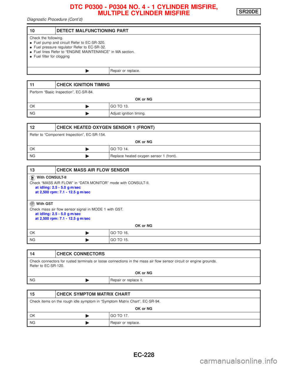
10 DETECT MALFUNCTIONING PART
Check the following.
IFuel pump and circuit Refer to EC-SR-320.
IFuel pressure regulator Refer to EC-SR-32.
IFuel lines Refer to ªENGINE MAINTENANCEº in MA section.
IFuel filter for clogging
©Repair or replace.
11 CHECK IGNITION TIMING
Perform ªBasic Inspectionº, EC-SR-84.
OK or NG
OK©GO TO 13.
NG©Adjust ignition timing.
12 CHECK HEATED OXYGEN SENSOR 1 (FRONT)
Refer to ªComponent Inspectionº, EC-SR-154.
OK or NG
OK©GO TO 14.
NG©Replace heated oxygen sensor 1 (front).
13 CHECK MASS AIR FLOW SENSOR
With CONSULT-II
Check ªMASS AIR FLOWº in ªDATA MONITORº mode with CONSULT-II.
at idling: 2.5 - 5.0 g×m/sec
at 2,500 rpm: 7.1 - 12.5 g×m/sec
With GST
Check mass air flow sensor signal in MODE 1 with GST.
at idling: 2.5 - 5.0 g×m/sec
at 2,500 rpm: 7.1 - 12.5 g×m/sec
OK or NG
OK©GO TO 16.
NG©GO TO 15.
14 CHECK CONNECTORS
Check connectors for rusted terminals or loose connections in the mass air flow sensor circuit or engine grounds.
Refer to EC-SR-120.
OK or NG
NG©Repair or replace it.
15 CHECK SYMPTOM MATRIX CHART
Check items on the rough idle symptom in ªSymptom Matrix Chartº, EC-SR-94.
OK or NG
OK©GO TO 17.
NG©Repair or replace.
DTC P0300 - P0304 NO.4-1CYLINDER MISFIRE,
MULTIPLE CYLINDER MISFIRESR20DE
Diagnostic Procedure (Cont'd)
EC-228
Page 1553 of 2267
Removal and InstallationNCEM0006
1. Oil pressure switch
2. EGR valve*
3. EGR guide tube*
4. Air relief plug5. Intake manifold
6. Intake manifold upper support
7. Intake manifold rear supports
8. Oil filter9. Thermostat
10. Water pump
11. Water pump pulley
*: If so equipped
YEM026
OUTER COMPONENT PARTSQG
Removal and Installation
EM-13
Page 1606 of 2267

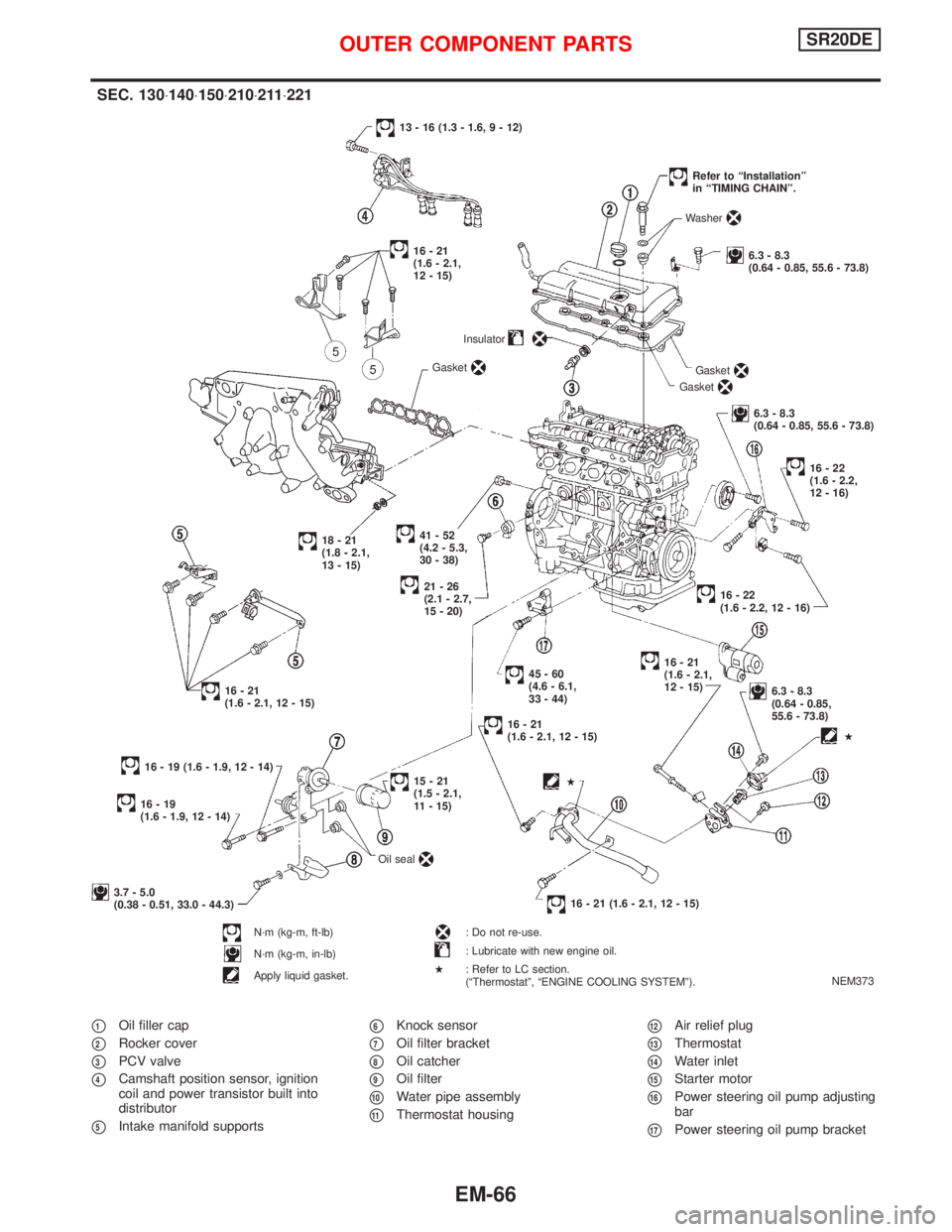
p1Oil filler cap
p2Rocker cover
p3PCV valve
p4Camshaft position sensor, ignition
coil and power transistor built into
distributor
p5Intake manifold supports
p6Knock sensor
p7Oil filter bracket
p8Oil catcher
p9Oil filter
p10Water pipe assembly
p11Thermostat housing
p12Air relief plug
p13Thermostat
p14Water inlet
p15Starter motor
p16Power steering oil pump adjusting
bar
p17Power steering oil pump bracket
NEM373
SEC. 130×140×150×210×211×221
.41-52
(4.2 - 5.3,
30 - 38)Insulator
21-26
(2.1 - 2.7,
15 - 20)
18-21
(1.8 - 2.1,
13 - 15)
16-21
(1.6 - 2.1, 12 - 15)
45-60
(4.6 - 6.1,
33 - 44)
16-21
(1.6 - 2.1, 12 - 15)
16 - 19 (1.6 - 1.9, 12 - 14)Gasket
13 - 16 (1.3 - 1.6, 9 - 12)
Gasket
Gasket
Washer
6.3 - 8.3
(0.64 - 0.85, 55.6 - 73.8)
Refer to ªInstallationº
in ªTIMING CHAINº.
6.3 - 8.3
(0.64 - 0.85, 55.6 - 73.8)
16-22
(1.6 - 2.2,
12 - 16)
.16-22
(1.6 - 2.2, 12 - 16)
16-21
(1.6 - 2.1,
12 - 15)
6.3 - 8.3
(0.64 - 0.85,
55.6 - 73.8)
16 - 21 (1.6 - 2.1, 12 - 15)
16-19
(1.6 - 1.9, 12 - 14)
15-21
(1.5 - 2.1,
11 - 15)
3.7 - 5.0
(0.38 - 0.51, 33.0 - 44.3)
N´m (kg-m, ft-lb)
N´m (kg-m, in-lb)
Apply liquid gasket.Oil seal
: Do not re-use.
: Lubricate with new engine oil.
: Refer to LC section.
(ªThermostatº, ªENGINE COOLING SYSTEMº).
H
H
H
16-21
(1.6 - 2.1,
12 - 15)
OUTER COMPONENT PARTSSR20DE
EM-66