Page 896 of 2267
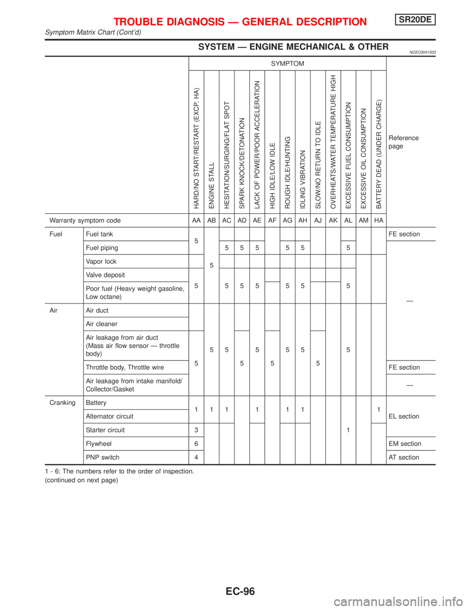
SYSTEM Ð ENGINE MECHANICAL & OTHERNCEC0041S03
SYMPTOM
Reference
page
HARD/NO START/RESTART (EXCP. HA)
ENGINE STALL
HESITATION/SURGING/FLAT SPOT
SPARK KNOCK/DETONATION
LACK OF POWER/POOR ACCELERATION
HIGH IDLE/LOW IDLE
ROUGH IDLE/HUNTING
IDLING VIBRATION
SLOW/NO RETURN TO IDLE
OVERHEATS/WATER TEMPERATURE HIGH
EXCESSIVE FUEL CONSUMPTION
EXCESSIVE OIL CONSUMPTION
BATTERY DEAD (UNDER CHARGE)
Warranty symptom code AA AB AC AD AE AF AG AH AJ AK AL AM HA
Fuel Fuel tank
5
5FE section
Fuel piping 5 5 5 5 5 5
Ð Vapor lock
Valve deposit
5 555 55 5
Poor fuel (Heavy weight gasoline,
Low octane)
Air Air duct
55555 5 Air cleaner
Air leakage from air duct
(Mass air flow sensor Ð throttle
body)
5555
Throttle body, Throttle wireFE section
Air leakage from intake manifold/
Collector/GasketÐ
Cranking Battery
111111
11
EL section Alternator circuit
Starter circuit 3
Flywheel 6 EM section
PNP switch 4 AT section
1 - 6: The numbers refer to the order of inspection.
(continued on next page)
TROUBLE DIAGNOSIS Ð GENERAL DESCRIPTIONSR20DE
Symptom Matrix Chart (Cont'd)
EC-96
Page 897 of 2267
SYMPTOM
Reference
page
HARD/NO START/RESTART (EXCP. HA)
ENGINE STALL
HESITATION/SURGING/FLAT SPOT
SPARK KNOCK/DETONATION
LACK OF POWER/POOR ACCELERATION
HIGH IDLE/LOW IDLE
ROUGH IDLE/HUNTING
IDLING VIBRATION
SLOW/NO RETURN TO IDLE
OVERHEATS/WATER TEMPERATURE HIGH
EXCESSIVE FUEL CONSUMPTION
EXCESSIVE OIL CONSUMPTION
BATTERY DEAD (UNDER CHARGE)
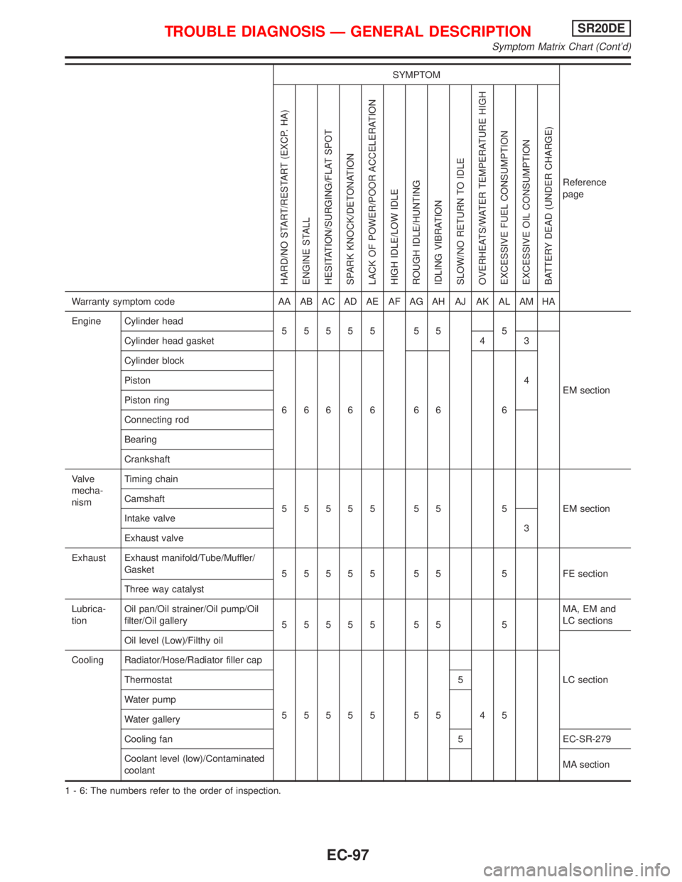
Warranty symptom code AA AB AC AD AE AF AG AH AJ AK AL AM HA
Engine Cylinder head
55555 55 5
EM section Cylinder head gasket 4 3
Cylinder block
66666 66 64 Piston
Piston ring
Connecting rod
Bearing
Crankshaft
Valve
mecha-
nismTiming chain
55555 55 5 EMsection Camshaft
Intake valve
3
Exhaust valve
Exhaust Exhaust manifold/Tube/Muffler/
Gasket
55555 55 5 FEsection
Three way catalyst
Lubrica-
tionOil pan/Oil strainer/Oil pump/Oil
filter/Oil gallery
55555 55 5MA, EM and
LC sections
Oil level (Low)/Filthy oil
LC section Cooling Radiator/Hose/Radiator filler cap
55555 55 45 Thermostat 5
Water pump
Water gallery
Cooling fan 5 EC-SR-279
Coolant level (low)/Contaminated
coolantMA section
1 - 6: The numbers refer to the order of inspection.
TROUBLE DIAGNOSIS Ð GENERAL DESCRIPTIONSR20DE
Symptom Matrix Chart (Cont'd)
EC-97
Page 1063 of 2267
DescriptionNCEC0279SYSTEM DESCRIPTIONNCEC0279S01
Sensor Input Signal to ECMECM func-
tionActuator
Camshaft position sensor Engine speed
ECM IACV-AAC valve Engine coolant temperature sensor Engine coolant temperature
Ignition switch Start signal
Throttle position sensor Throttle position
PNP switch Park/Neutral position
Air conditioner switch Air conditioner operation
Power steering oil pressure switch Power steering load signal
Battery Battery voltage
Vehicle speed sensor or ABS actuator and
electric unit (control unit)Vehicle speed
Cooling fan Cooling fan operation
Electrical load Electrical load signal
This system automatically controls engine idle speed to a specified
level. Idle speed is controlled through fine adjustment of the
amount of air which by-passes the throttle valve via IACV-AAC
valve. The IACV-AAC valve changes the opening of the air by-pass
passage to control the amount of auxiliary air. This valve is actu-
ated by a step motor built into the valve, which moves the valve in
the axial direction in steps corresponding to the ECM output sig-
nals. One step of IACV-AAC valve movement causes the respec-
tive opening of the air by-pass passage. (i.e. when the step
advances, the opening is enlarged.) The opening of the valve is
varied to allow for optimum control of the engine idling speed. The
crankshaft position sensor (POS) detects the actual engine speed
and sends a signal to the ECM. The ECM then controls the step
position of the IACV-AAC valve so that engine speed coincides with
the target value memorized in ECM. The target engine speed is the
lowest speed at which the engine can operate steadily. The opti-
mum value stored in the ECM is determined by taking into consid-
eration various engine conditions, such as during warm up,
deceleration, and engine load (air conditioner, power steering, cool-
ing fan operation and electrical load).
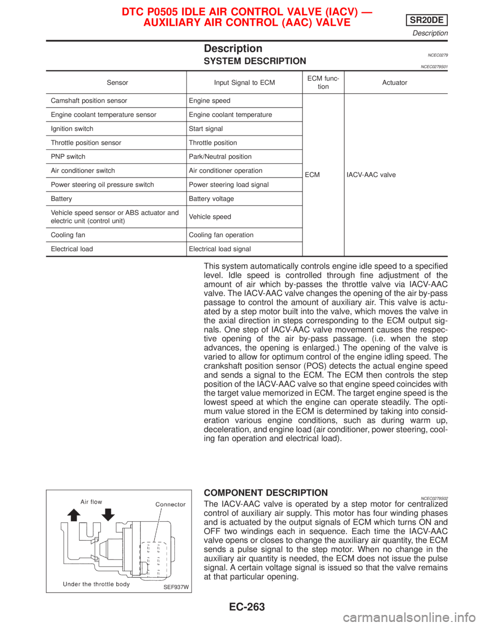
COMPONENT DESCRIPTIONNCEC0279S02The IACV-AAC valve is operated by a step motor for centralized
control of auxiliary air supply. This motor has four winding phases
and is actuated by the output signals of ECM which turns ON and
OFF two windings each in sequence. Each time the IACV-AAC
valve opens or closes to change the auxiliary air quantity, the ECM
sends a pulse signal to the step motor. When no change in the
auxiliary air quantity is needed, the ECM does not issue the pulse
signal. A certain voltage signal is issued so that the valve remains
at that particular opening.
SEF937W
DTC P0505 IDLE AIR CONTROL VALVE (IACV) Ð
AUXILIARY AIR CONTROL (AAC) VALVESR20DE
Description
EC-263
Page 1080 of 2267
CONSULT-II Reference Value in Data Monitor
Mode
NCEC0486Specification data are reference values.
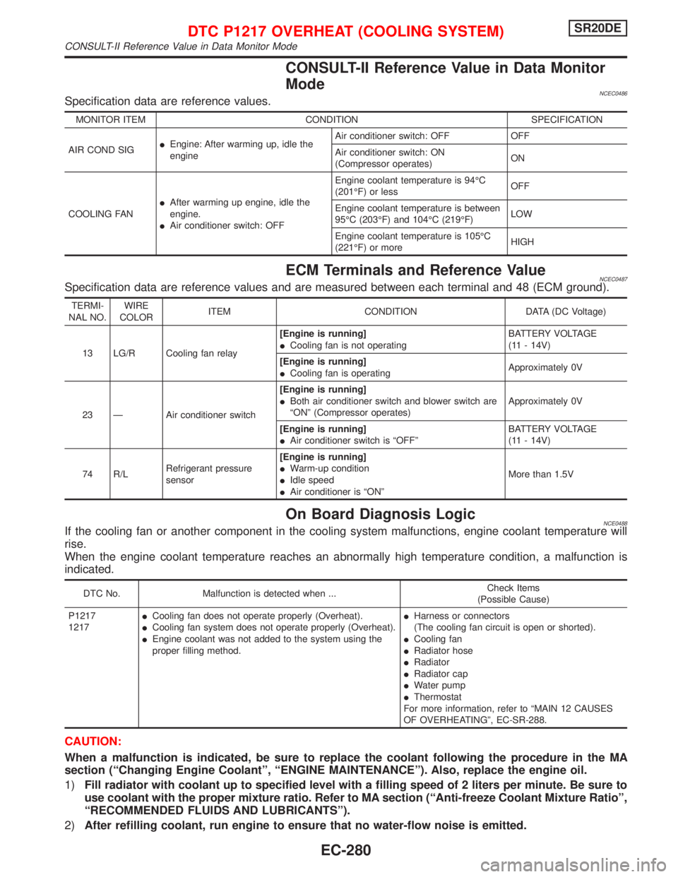
MONITOR ITEM CONDITION SPECIFICATION
AIR COND SIGIEngine: After warming up, idle the
engineAir conditioner switch: OFF OFF
Air conditioner switch: ON
(Compressor operates)ON
COOLING FANIAfter warming up engine, idle the
engine.
IAir conditioner switch: OFFEngine coolant temperature is 94ÉC
(201ÉF) or lessOFF
Engine coolant temperature is between
95ÉC (203ÉF) and 104ÉC (219ÉF)LOW
Engine coolant temperature is 105ÉC
(221ÉF) or moreHIGH
ECM Terminals and Reference ValueNCEC0487Specification data are reference values and are measured between each terminal and 48 (ECM ground).
TERMI-
NAL NO.WIRE
COLORITEM CONDITION DATA (DC Voltage)
13 LG/R Cooling fan relay[Engine is running]
ICooling fan is not operatingBATTERY VOLTAGE
(11 - 14V)
[Engine is running]
ICooling fan is operatingApproximately 0V
23 Ð Air conditioner switch[Engine is running]
IBoth air conditioner switch and blower switch are
ªONº (Compressor operates)Approximately 0V
[Engine is running]
IAir conditioner switch is ªOFFºBATTERY VOLTAGE
(11 - 14V)
74 R/LRefrigerant pressure
sensor[Engine is running]
IWarm-up condition
IIdle speed
IAir conditioner is ªONºMore than 1.5V
On Board Diagnosis LogicNCE0488If the cooling fan or another component in the cooling system malfunctions, engine coolant temperature will
rise.
When the engine coolant temperature reaches an abnormally high temperature condition, a malfunction is
indicated.
DTC No. Malfunction is detected when ...Check Items
(Possible Cause)
P1217
1217ICooling fan does not operate properly (Overheat).
ICooling fan system does not operate properly (Overheat).
IEngine coolant was not added to the system using the
proper filling method.IHarness or connectors
(The cooling fan circuit is open or shorted).
ICooling fan
IRadiator hose
IRadiator
IRadiator cap
IWater pump
IThermostat
For more information, refer to ªMAIN 12 CAUSES
OF OVERHEATINGº, EC-SR-288.
CAUTION:
When a malfunction is indicated, be sure to replace the coolant following the procedure in the MA
section (ªChanging Engine Coolantº, ªENGINE MAINTENANCEº). Also, replace the engine oil.
1)Fill radiator with coolant up to specified level with a filling speed of 2 liters per minute. Be sure to
use coolant with the proper mixture ratio. Refer to MA section (ªAnti-freeze Coolant Mixture Ratioº,
ªRECOMMENDED FLUIDS AND LUBRICANTSº).
2)After refilling coolant, run engine to ensure that no water-flow noise is emitted.
DTC P1217 OVERHEAT (COOLING SYSTEM)SR20DE
CONSULT-II Reference Value in Data Monitor Mode
EC-280
Page 1130 of 2267
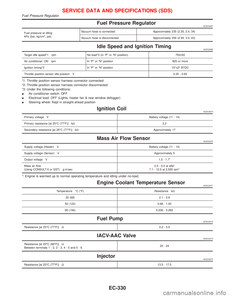
Fuel Pressure RegulatorNCEC0467
Fuel pressure at idling
kPa (bar, kg/cm2, psi)Vacuum hose is connected Approximately 235 (2.35, 2.4, 34)
Vacuum hose is disconnected Approximately 294 (2.94, 3.0, 43)
Idle Speed and Ignition TimingNCEC0468
Target idle speed*1 rpm No-load*3 (in ªPº or ªNº position) 750 50
Air conditioner: ON rpm In ªPº or ªNº position 825 or more
Ignition timing*2 In ªPº or ªNº position 15É 2É BTDC
Throttle position sensor idle position V0.35 - 0.65
*1: Throttle position sensor harness connector connected
*2: Throttle position sensor harness connector disconnected
*3: Under the following conditions:
IAir conditioner switch: OFF
IElectrical load: OFF (Lights, heater fan & rear window defogger)
ISteering wheel: Kept in straight-ahead position
Ignition CoilNCEC0574
Primary voltage VBattery voltage (11 - 14)
Primary resistance [at 25ÉC (77ÉF)] kW2.2
Secondary resistance [at 25ÉC (77ÉF)] kWApproximately 17
Mass Air Flow SensorNCEC0470
Supply voltage (Heater) VBattery voltage (11 - 14)
Supply voltage (Sensor) VApproximately 5
Output voltage V1.3 - 1.7*
Mass air flow
(Using CONSULT-II or GST) g×m/sec2.5 - 5.0 at idle*
7.1 - 12.5 at 2,500 rpm*
*: Engine is warmed up to normal operating temperature and idling under no-load.
Engine Coolant Temperature SensorNCEC0471
Temperature ÉC (ÉF) Resistance kW
20 (68) 2.1 - 2.9
50 (122) 0.68 - 1.00
90 (194) 0.236 - 0.260
Fuel PumpNCEC0473
Resistance [at 25ÉC (77ÉF)]W0.2 - 5.0
IACV-AAC ValveNCEC0474
Resistance [at 20ÉC (68ÉF)]W
Between terminals1-2,2-3,4-5and5-620-24
InjectorNCEC0475
Resistance [at 25ÉC (77ÉF)]W13.5 - 17.5
SERVICE DATA AND SPECIFICATIONS (SDS)
Fuel Pressure Regulator
EC-330
Page 1176 of 2267
�1Bearing retainer
�2Pinion shaft
�3Clutch assembly
�4Return spring
�5Pinion stopper
�6Stopper clip
�7Gear case
�8Adjusting plates
�9Torsion spring
�10Shift lever
�11Magnetic switch assembly
�12Armature assembly
�13Field coil
�14Yoke
�15Brush (+)
�16Brush spring
�17Brush (�)
�18Brush holder
�19Rear cover
�20Through-bolt
NEL299
SEC. 233
S13 - 305
6.4 - 7.8 (0.65 - 0.80, 56.4 - 69.4)
7.4 - 9.8
(0.75 - 1.00,
65.1 - 86.8)
N·m (kg-m, in-lb)
High-temperature grease point
STARTING SYSTEM
Construction (Cont’d)
EL-44
Page 1178 of 2267
�1Bearing retainer
�2Pinion shaft
�3Clutch assembly
�4Return spring
�5Pinion stopper
�6Stopper clip
�7Gear case
�8Dust cover
�9Torsion spring
�10Shift lever
�11Magnetic switch assembly
�12Armature assembly
�13Field coil
�14Yoke
�15Brush (+)
�16Brush spring
�17Brush (�)
�18Brush holder
�19Rear cover
�20Through-bolt
MEL233FB
SEC. 233
S13-531
6.4 - 7.8 (0.65 - 0.80, 56.4 - 69.4)
7.4 - 9.8
(0.75 - 1.00,
65.1 - 86.8)
N·m (kg-m, in-lb)
High temperature grease point
STARTING SYSTEM
Construction (Cont’d)
EL-46
Page 1555 of 2267
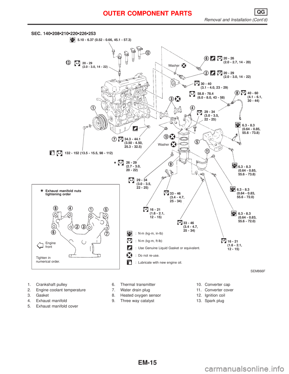
1. Crankshaft pulley
2. Engine coolant temperature
3. Gasket
4. Exhaust manifold
5. Exhaust manifold cover6. Thermal transmitter
7. Water drain plug
8. Heated oxygen sensor
9. Three way catalyst10. Converter cap
11. Converter cover
12. Ignition coil
13. Spark plug
SEM866F
5.10 - 6.37 (0.52 - 0.66, 45.1 - 57.3)
p1320-29
(2.0 - 3.0, 14 - 22)
132 - 152 (13.5 - 15.5, 98 - 112)34.3 - 44.1
(3.50 - 4.50,
25.3 - 32.5)
H
26-29
(2.7 - 3.0,
20 - 22)6.3 - 8.3
(0.64 - 0.85,
55.6 - 73.8)
6.3 - 8.3
(0.64 - 0.85,
55.6 - 73.8)
6.3 - 8.3
(0.64 - 0.83,
55.6 - 72.0)
6.3 - 8.3
(0.64 - 0.83,
55.6 - 72.0) WasherWasher
20-26
(2.0 - 2.7, 14 - 20)
20-29
(2.0 - 3.0, 14 - 22)
30-40
(3.1 - 4.0, 23 - 29)
58.8 - 78.4
(6.0 - 8.0, 43 - 58)40-60
(4.1 - 6.1,
30 - 44)
29-34
(3.0 - 3.5,
22 - 25)
29-34
(3.0 - 3.5,
22 - 25)
33-46
(3.4 - 4.7,
25 - 34)
16-21
(1.6 - 2.1,
12 - 15)
33-46
(3.4 - 4.7,
25 - 34)
16-21
(1.6 - 2.1,
12 - 15) Exhaust manifold nuts
tightening order
Engine
front
Tighten in
numerical order.: N´m (kg-m, in-lb)
: N´m (kg-m, ft-lb)
: Use Genuine Liquid Gasket or equivalent.
: Do not re-use.
: Lubricate with new engine oil.
OUTER COMPONENT PARTSQG
Removal and Installation (Cont'd)
EM-15