1999 NISSAN PRIMERA ECU
[x] Cancel search: ECUPage 7 of 2267
Precautions for Supplemental Restraint System
(SRS) ªAIR BAGº and ªSEAT BELT
PRE-TENSIONERº
NCAT0002The Supplemental Restraint System ªAIR BAGº and ªSEAT BELT PRE-TENSIONERº, used along with a seat
belt, help to reduce the risk or severity of injury to the driver and front passenger in a frontal collision. The
Supplemental Restraint System consists of air bag modules (located in the center of the steering wheel and
on the instrument panel on the passenger side), seat belt pre-tensioners, a diagnosis sensor unit, warning
lamp, wiring harness and spiral cable.
In addition to the supplemental air bag modules for a frontal collision, the supplemental side air bag used along
with the seat belt helps to reduce the risk or severity of injury to the driver and front passenger in a side col-
lision. The supplemental side air bag consists of air bag modules (located in the outer side of front seats),
satellite sensor, diagnosis sensor unit (one of components of supplemental air bags for a frontal collision),
wiring harness, warning lamp (one of components of supplemental air bags for a frontal collision). Information
necessary to service the system safely is included in theRS sectionof this Service Manual.
WARNING:
ITo avoid rendering the SRS inoperative, which could increase the risk of personal injury or death
in the event of a collision which would result in air bag inflation, all maintenance must be performed
by an authorized NISSAN dealer.
IImproper maintenance, including incorrect removal and installation of the SRS, can lead to per-
sonal injury caused by unintentional activation of the system.
IDo not use electrical test equipment on any circuit related to the SRS unless instructed to in this
Service Manual. SRS wiring harnesses (except ªSEAT BELT PRE-TENSIONERº connector) can be
identified with yellow harness connector (and with yellow harness protector or yellow insulation
tape before the harness connectors).
Precautions for On Board Diagnostic (OBD)
System of CVT and Engine
NCAT0198The ECM has an on board diagnostic system. It will light up the malfunction indicator (MI) to warn the driver
of a malfunction causing emission deterioration.
CAUTION:
IBe sure to turn the ignition switch ªOFFº and disconnect the negative battery terminal before any
repair or inspection work. The open/short circuit of related switches, sensors, solenoid valves, etc.
will cause the MI to light up.
IBe sure to connect and lock the connectors securely after work. A loose (unlocked) connector will
cause the MI to light up due to an open circuit. (Be sure the connector is free from water, grease,
dirt, bent terminals, etc.)
IBe sure to route and secure the harnesses properly after work. Interference of the harness with a
bracket, etc. may cause the MI to light up due to a short circuit.
IBe sure to connect rubber tubes properly after work. A misconnected or disconnected rubber tube
may cause the MI to light up due to a malfunction of the EGR system or fuel injection system, etc.
IBe sure to erase the unnecessary malfunction information (repairs completed) from the TCM and
ECM before returning the vehicle to the customer.
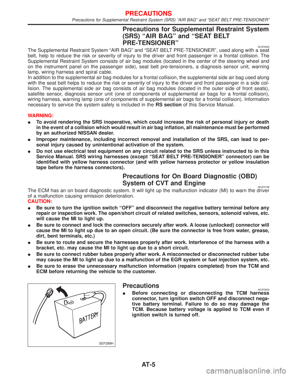
PrecautionsNCAT0003IBefore connecting or disconnecting the TCM harness
connector, turn ignition switch OFF and disconnect nega-
tive battery terminal. Failure to do so may damage the
TCM. Because battery voltage is applied to TCM even if
ignition switch is turned off.
SEF289H
PRECAUTIONS
Precautions for Supplemental Restraint System (SRS) ªAIR BAGº and ªSEAT BELT PRE-TENSIONERº
AT-5
Page 51 of 2267
DIAGNOSTIC TROUBLE CODE (DTC) CONFIRMATION
PROCEDURE
NCAT0032S03CAUTION:
Always drive vehicle at a safe speed.
NOTE:
If ªDIAGNOSTIC TROUBLE CODE CONFIRMATION PROCE-
DUREº has been previously conducted, always turn ignition
switch ªOFFº and wait at least 5 seconds before conducting
the next test.
After the repair, perform the following procedure to confirm the
malfunction is eliminated.
With CONSULT-II
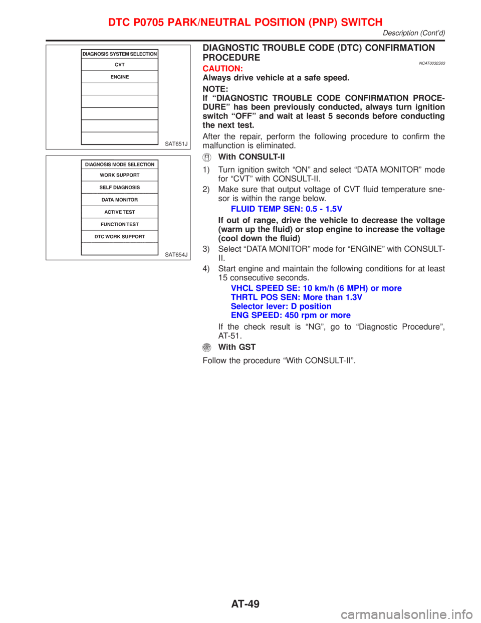
1) Turn ignition switch ªONº and select ªDATA MONITORº mode
for ªCVTº with CONSULT-II.
2) Make sure that output voltage of CVT fluid temperature sne-
sor is within the range below.
FLUID TEMP SEN: 0.5 - 1.5V
If out of range, drive the vehicle to decrease the voltage
(warm up the fluid) or stop engine to increase the voltage
(cool down the fluid)
3) Select ªDATA MONITORº mode for ªENGINEº with CONSULT-
II.
4) Start engine and maintain the following conditions for at least
15 consecutive seconds.
VHCL SPEED SE: 10 km/h (6 MPH) or more
THRTL POS SEN: More than 1.3V
Selector lever: D position
ENG SPEED: 450 rpm or more
If the check result is ªNGº, go to ªDiagnostic Procedureº,
AT-51.
With GST
Follow the procedure ªWith CONSULT-IIº.
SAT651J
SAT654J
DTC P0705 PARK/NEUTRAL POSITION (PNP) SWITCH
Description (Cont'd)
AT-49
Page 53 of 2267
Diagnostic ProcedureNCAT0033
1 CHECK PNP SWITCH CIRCUIT (With CONSULT-II)
With CONSULT-II
1. Turn ignition switch to ªONº position.
(Do not start engine.)
2. Select ªECU INPUT SIGNALSº in ªDATA MONITORº mode for ªCVTº with CONSULT-II.
SAT651J3. Read out ªP/Nº, ªRº, ªDº and ªLº position switches moving selector lever to each position.
Check the signal of the selector lever position is indicated properly.
OK or NG
OK©GO TO 3.
NG©Check the following items:
IPNP switch
Refer to ªComponent Inspectionº, AT-53.
IHarness for short or open between ignition switch and PNP switch (Main harness)
IHarness for short or open between PNP switch and TCM (Main harness)
IIgnition switch and fuse
Refer to EL section (ªPOWER SUPPLY ROUTINGº).
IDiode (P, N positions)
2 CHECK PNP SWITCH CIRCUIT (Without CONSULT-II)
Without CONSULT-II
1. Turn ignition switch to ªONº position.
(Do not start engine.)
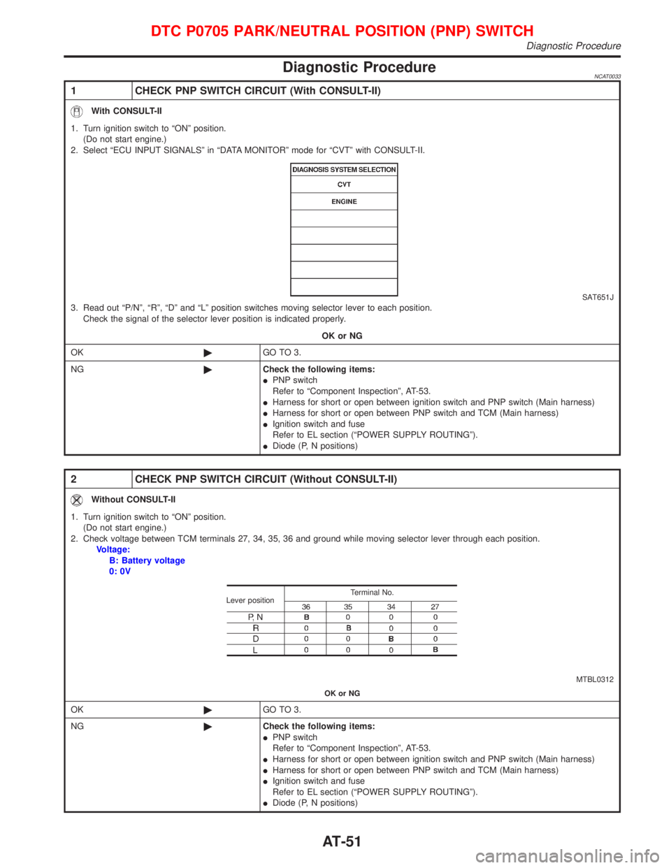
2. Check voltage between TCM terminals 27, 34, 35, 36 and ground while moving selector lever through each position.
Voltage:
B: Battery voltage
0: 0V
MTBL0312 Terminal No.
Lever position
OK or NG
OK©GO TO 3.
NG©Check the following items:
IPNP switch
Refer to ªComponent Inspectionº, AT-53.
IHarness for short or open between ignition switch and PNP switch (Main harness)
IHarness for short or open between PNP switch and TCM (Main harness)
IIgnition switch and fuse
Refer to EL section (ªPOWER SUPPLY ROUTINGº).
IDiode (P, N positions)
DTC P0705 PARK/NEUTRAL POSITION (PNP) SWITCH
Diagnostic Procedure
AT-51
Page 59 of 2267
Diagnostic ProcedureNCAT0036
1 CHECK CVT FLUID TEMPERATURE SENSOR WITH TERMINAL CORD ASSEMBLY
1. Turn ignition switch to ªOFFº position.
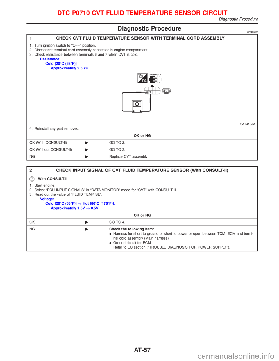
2. Disconnect terminal cord assembly connector in engine compartment.
3. Check resistance between terminals 6 and 7 when CVT is cold.
Resistance:
Cold [20ÉC (68ÉF)]
Approximately 2.5 kW
SAT419JA4. Reinstall any part removed.
OK or NG
OK (With CONSULT-II)©GO TO 2.
OK (Without CONSULT-II)©GO TO 3.
NG©Replace CVT assembly
2 CHECK INPUT SIGNAL OF CVT FLUID TEMPERATURE SENSOR (With CONSULT-II)
With CONSULT-II
1. Start engine.
2. Select ªECU INPUT SIGNALSº in ªDATA MONITORº mode for ªCVTº with CONSULT-II.
3. Read out the value of ªFLUID TEMP SEº.
Voltage:
Cold [20ÉC (68ÉF)]®Hot [80ÉC (176ÉF)]:
Approximately 1.5V®0.5V
OK or NG
OK©GO TO 4.
NG©Check the following item:
IHarness for short to ground or short to power or open between TCM, ECM and termi-
nal cord assembly (Main harness)
IGround circuit for ECM
Refer to EC section (ªTROUBLE DIAGNOSIS FOR POWER SUPPLYº).
DTC P0710 CVT FLUID TEMPERATURE SENSOR CIRCUIT
Diagnostic Procedure
AT-57
Page 61 of 2267
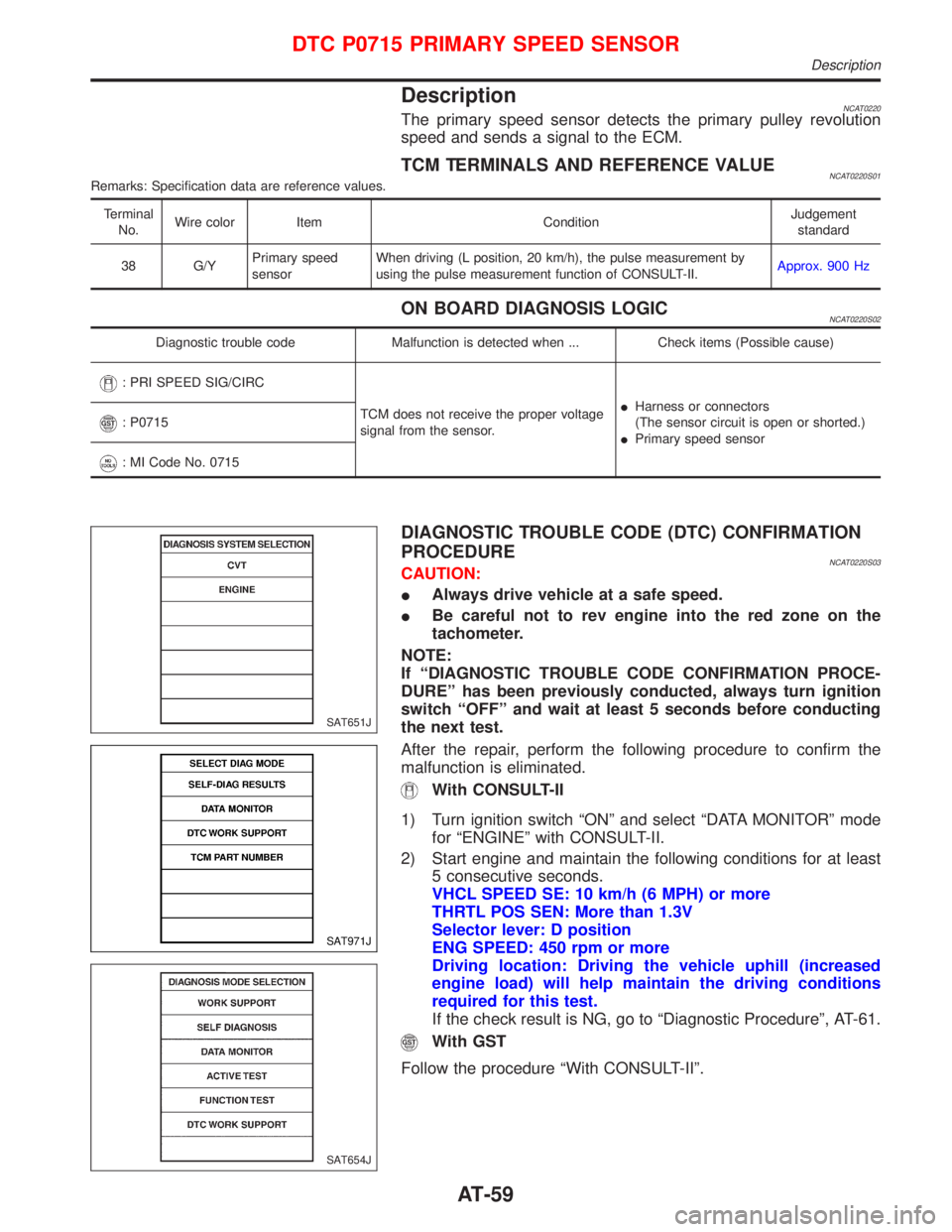
DescriptionNCAT0220The primary speed sensor detects the primary pulley revolution
speed and sends a signal to the ECM.
TCM TERMINALS AND REFERENCE VALUENCAT0220S01Remarks: Specification data are reference values.
Terminal
No.Wire color Item ConditionJudgement
standard
38 G/YPrimary speed
sensorWhen driving (L position, 20 km/h), the pulse measurement by
using the pulse measurement function of CONSULT-II.Approx. 900 Hz
ON BOARD DIAGNOSIS LOGICNCAT0220S02
Diagnostic trouble code Malfunction is detected when ... Check items (Possible cause)
: PRI SPEED SIG/CIRC
TCM does not receive the proper voltage
signal from the sensor.IHarness or connectors
(The sensor circuit is open or shorted.)
IPrimary speed sensor
: P0715
: MI Code No. 0715
DIAGNOSTIC TROUBLE CODE (DTC) CONFIRMATION
PROCEDURE
NCAT0220S03CAUTION:
IAlways drive vehicle at a safe speed.
IBe careful not to rev engine into the red zone on the
tachometer.
NOTE:
If ªDIAGNOSTIC TROUBLE CODE CONFIRMATION PROCE-
DUREº has been previously conducted, always turn ignition
switch ªOFFº and wait at least 5 seconds before conducting
the next test.
After the repair, perform the following procedure to confirm the
malfunction is eliminated.
With CONSULT-II
1) Turn ignition switch ªONº and select ªDATA MONITORº mode
for ªENGINEº with CONSULT-II.
2) Start engine and maintain the following conditions for at least
5 consecutive seconds.
VHCL SPEED SE: 10 km/h (6 MPH) or more
THRTL POS SEN: More than 1.3V
Selector lever: D position
ENG SPEED: 450 rpm or more
Driving location: Driving the vehicle uphill (increased
engine load) will help maintain the driving conditions
required for this test.
If the check result is NG, go to ªDiagnostic Procedureº, AT-61.
With GST
Follow the procedure ªWith CONSULT-IIº.
SAT651J
SAT971J
SAT654J
DTC P0715 PRIMARY SPEED SENSOR
Description
AT-59
Page 63 of 2267
Diagnostic ProcedureNCAT0222
1 CHECK PRIMARY SPEED SENSOR
Refer to ªComponent Inspectionº AT-65.
OK or NG
OK (With CONSULT-II)©GO TO 2.
OK (Without CONSULT-II)©GO TO 3.
NG©Repair or replace primary speed sensor.
2 CHECK INPUT SIGNAL (With CONSULT-II)
With CONSULT-II
1. Start engine.
2. Select ªECU INPUT SIGNALSº in ªDATA MONITORº mode for ªCVTº with CONSULT-II.
3. Read out the value of ªI/P PULLY SPDº while driving.
Check the value changes according to driving speed. (Almost same value as engine speed)
OK or NG
OK©GO TO 4.
NG©Check the following items:
IHarness for short or open between TCM, ECM and primary speed sensor (Main har-
ness)
IGround circuit for ECM
Refer to EC section (ªTROUBLE DIAGNOSIS FOR POWER SUPPLYº).
3 CHECK DTC
Perform Diagnostic Trouble Code (DTC) confirmation procedure, AT-62.
OK or NG
OK©INSPECTION END
NG©1. Perform TCM input/output signal inspection.
2. If NG, recheck TCM pin terminals for damage or loose connection with harness con-
nector.
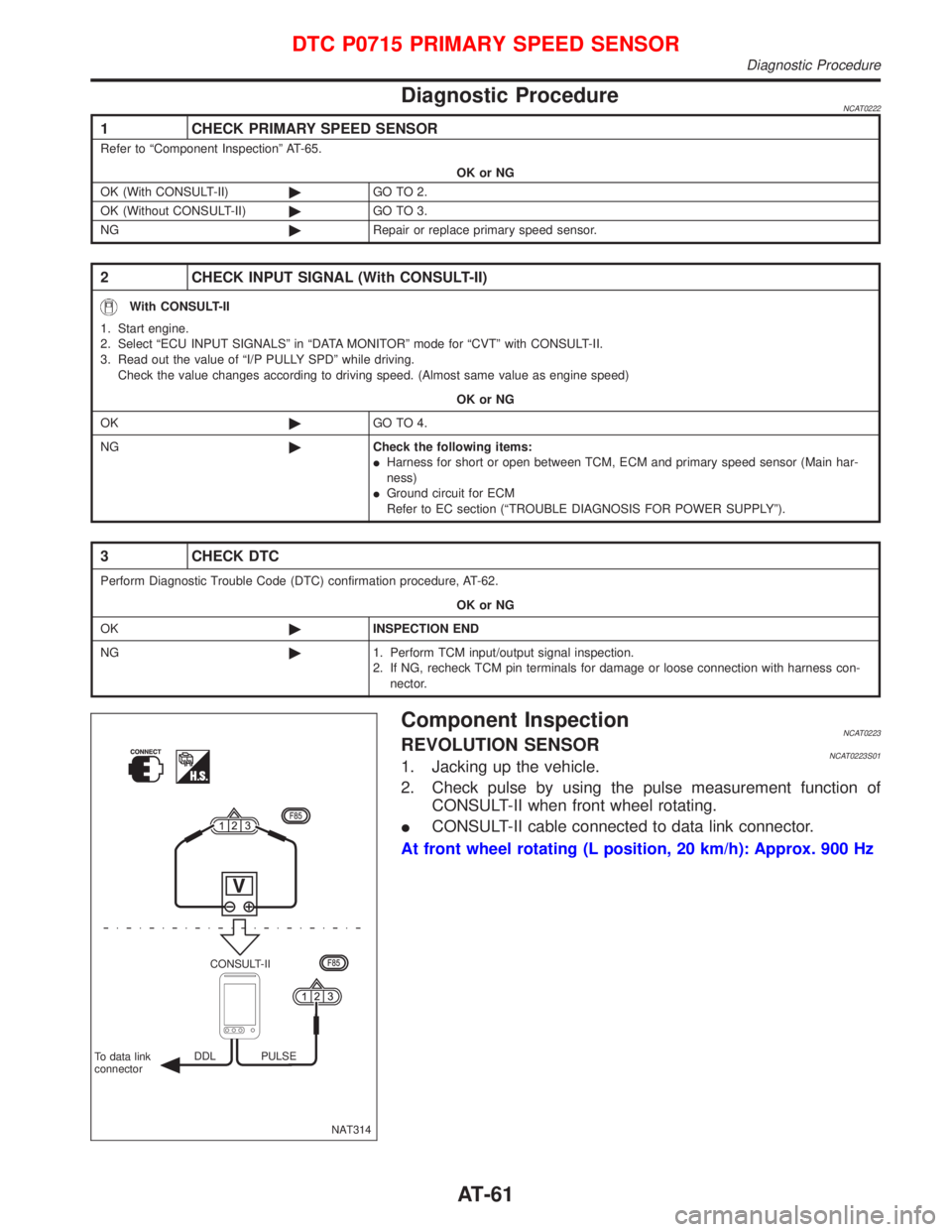
Component InspectionNCAT0223REVOLUTION SENSORNCAT0223S011. Jacking up the vehicle.
2. Check pulse by using the pulse measurement function of
CONSULT-II when front wheel rotating.
ICONSULT-II cable connected to data link connector.
At front wheel rotating (L position, 20 km/h): Approx. 900 Hz
NAT314 CONSULT-II
To data link
connectorDDL PULSE
DTC P0715 PRIMARY SPEED SENSOR
Diagnostic Procedure
AT-61
Page 65 of 2267
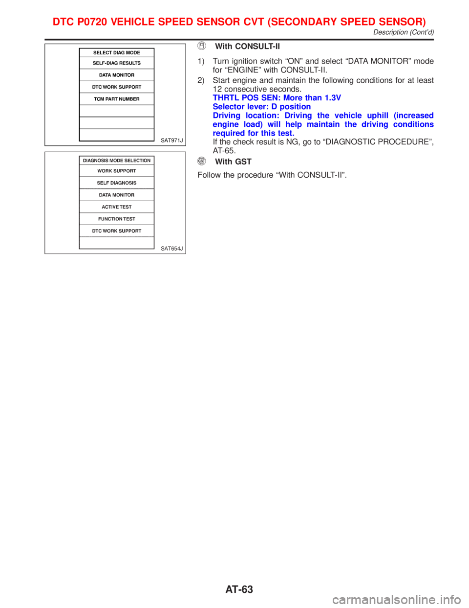
With CONSULT-II
1) Turn ignition switch ªONº and select ªDATA MONITORº mode
for ªENGINEº with CONSULT-II.
2) Start engine and maintain the following conditions for at least
12 consecutive seconds.
THRTL POS SEN: More than 1.3V
Selector lever: D position
Driving location: Driving the vehicle uphill (increased
engine load) will help maintain the driving conditions
required for this test.
If the check result is NG, go to ªDIAGNOSTIC PROCEDUREº,
AT-65.
With GST
Follow the procedure ªWith CONSULT-IIº.
SAT971J
SAT654J
DTC P0720 VEHICLE SPEED SENSOR CVT (SECONDARY SPEED SENSOR)
Description (Cont'd)
AT-63
Page 67 of 2267
Diagnostic ProcedureNCAT0039
1 CHECK SECONDARY SPEED SENSOR
Refer to ªComponent Inspectionº AT-65.
OK or NG
OK (With CONSULT-II)©GO TO 2.
OK (Without CONSULT-II)©GO TO 3.
NG©Repair or replace secondary speed sensor.
2 CHECK INPUT SIGNAL (With CONSULT-II)
With CONSULT-II
1. Start engine.
2. Select ªECU INPUT SIGNALSº in ªDATA MONITORº mode for ªCVTº with CONSULT-II.
3. Read out the value of ªVEHICLE SPEEDº while driving.
Check the value changes according to driving speed.
OK or NG
OK©GO TO 4.
NG©Check the following items:
IHarness for short or open between TCM, ECM and secondary speed sensor (Main
harness)
IGround circuit for ECM
Refer to EC section (ªTROUBLE DIAGNOSIS FOR POWER SUPPLYº).
3 CHECK DTC
Perform Diagnostic Trouble Code (DTC) confirmation procedure, AT-62.
OK or NG
OK©INSPECTION END
NG©1. Perform TCM input/output signal inspection.
2. If NG, recheck TCM pin terminals for damage or loose connection with harness con-
nector.
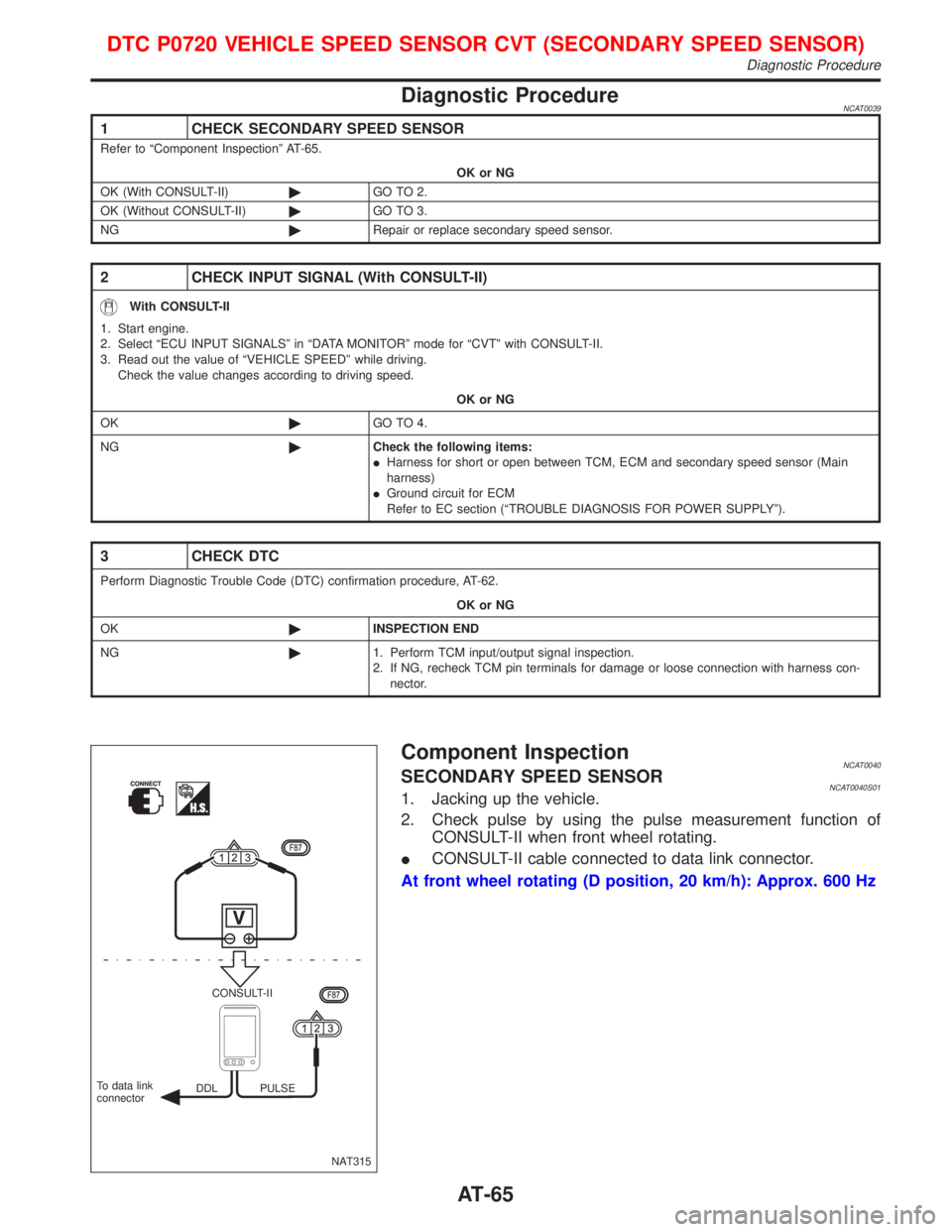
Component InspectionNCAT0040SECONDARY SPEED SENSORNCAT0040S011. Jacking up the vehicle.
2. Check pulse by using the pulse measurement function of
CONSULT-II when front wheel rotating.
ICONSULT-II cable connected to data link connector.
At front wheel rotating (D position, 20 km/h): Approx. 600 Hz
NAT315 CONSULT-II
DDL PULSE To data link
connector
DTC P0720 VEHICLE SPEED SENSOR CVT (SECONDARY SPEED SENSOR)
Diagnostic Procedure
AT-65