1999 NISSAN PRIMERA brake sensor
[x] Cancel search: brake sensorPage 176 of 2267
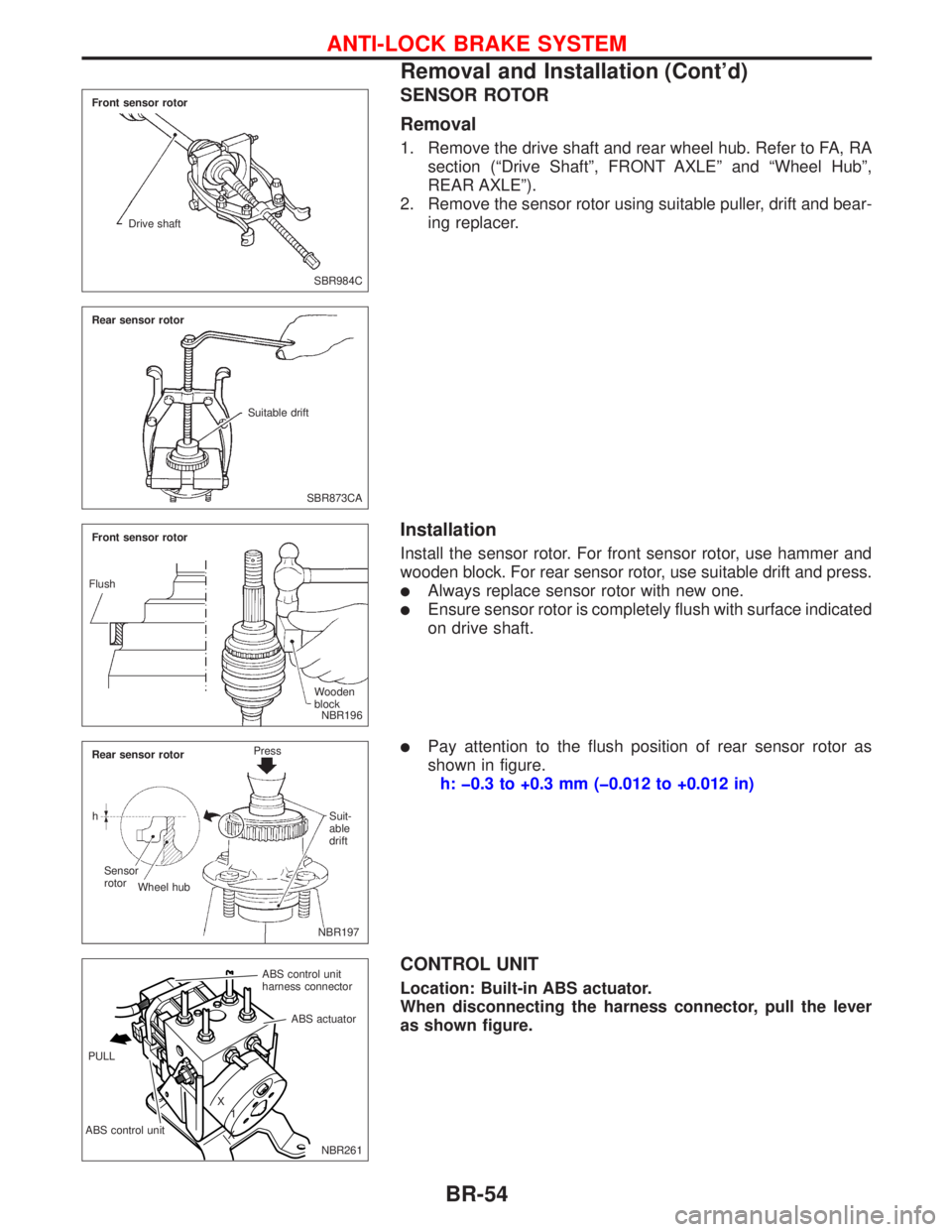
SENSOR ROTOR
Removal
1. Remove the drive shaft and rear wheel hub. Refer to FA, RA
section (ªDrive Shaftº, FRONT AXLEº and ªWheel Hubº,
REAR AXLEº).
2. Remove the sensor rotor using suitable puller, drift and bear-
ing replacer.
Installation
Install the sensor rotor. For front sensor rotor, use hammer and
wooden block. For rear sensor rotor, use suitable drift and press.
lAlways replace sensor rotor with new one.
lEnsure sensor rotor is completely flush with surface indicated
on drive shaft.
lPay attention to the flush position of rear sensor rotor as
shown in figure.
h: þ0.3 to +0.3 mm (þ0.012 to +0.012 in)
CONTROL UNIT
Location: Built-in ABS actuator.
When disconnecting the harness connector, pull the lever
as shown figure.
SBR984C Front sensor rotor
Drive shaft
SBR873CA Rear sensor rotor
Suitable drift
NBR196 Front sensor rotor
Wooden
block Flush
.NBR197 Rear sensor rotorPress
Suit-
able
drift
Sensor
rotor
Wheel hub h
NBR261 ABS control unit
harness connector
ABS control unitABS actuator
X
1
X PULL
ANTI-LOCK BRAKE SYSTEM
Removal and Installation (Cont'd)
BR-54
Page 179 of 2267
How to Perform Trouble Diagnoses for Quick
and Accurate Repair
INTRODUCTION
The ABS system has an electronic control unit to control major
braking functions. The control unit accepts input signals from
sensors and utilises the data to instantly drive the actuators. It is
essential that both input and output signals are correct and
stable. It is also important to check for conventional problems:
such as air leaks in booster lines, lack of brake fluid, or other
problems with the brake system.
It is much more difficult to diagnose a problem that occurs inter-
mittently rather than catastrophically. Most intermittent problems
are caused by poor electric connections or faulty wiring. In this
case, careful checking of suspicious circuits may help prevent
the unnecessary replacement of good parts.
A visual check may not be sufficient to find the cause of the
problems, so a road test should also be performed.
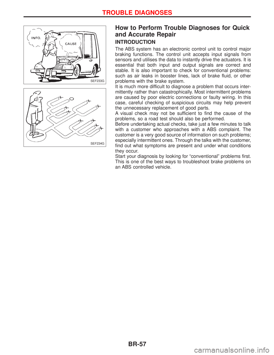
Before undertaking actual checks, take just a few minutes to talk
with a customer who approaches with a ABS complaint. The
customer is a very good source of information on such problems;
especially intermittent ones. Through the talks with the customer,
find out what symptoms are present and under what conditions
they occur.
Start your diagnosis by looking for ªconventionalº problems first.
This is one of the best ways to troubleshoot brake problems on
an ABS controlled vehicle.
SEF233G
SEF234G
TROUBLE DIAGNOSES
BR-57
Page 182 of 2267
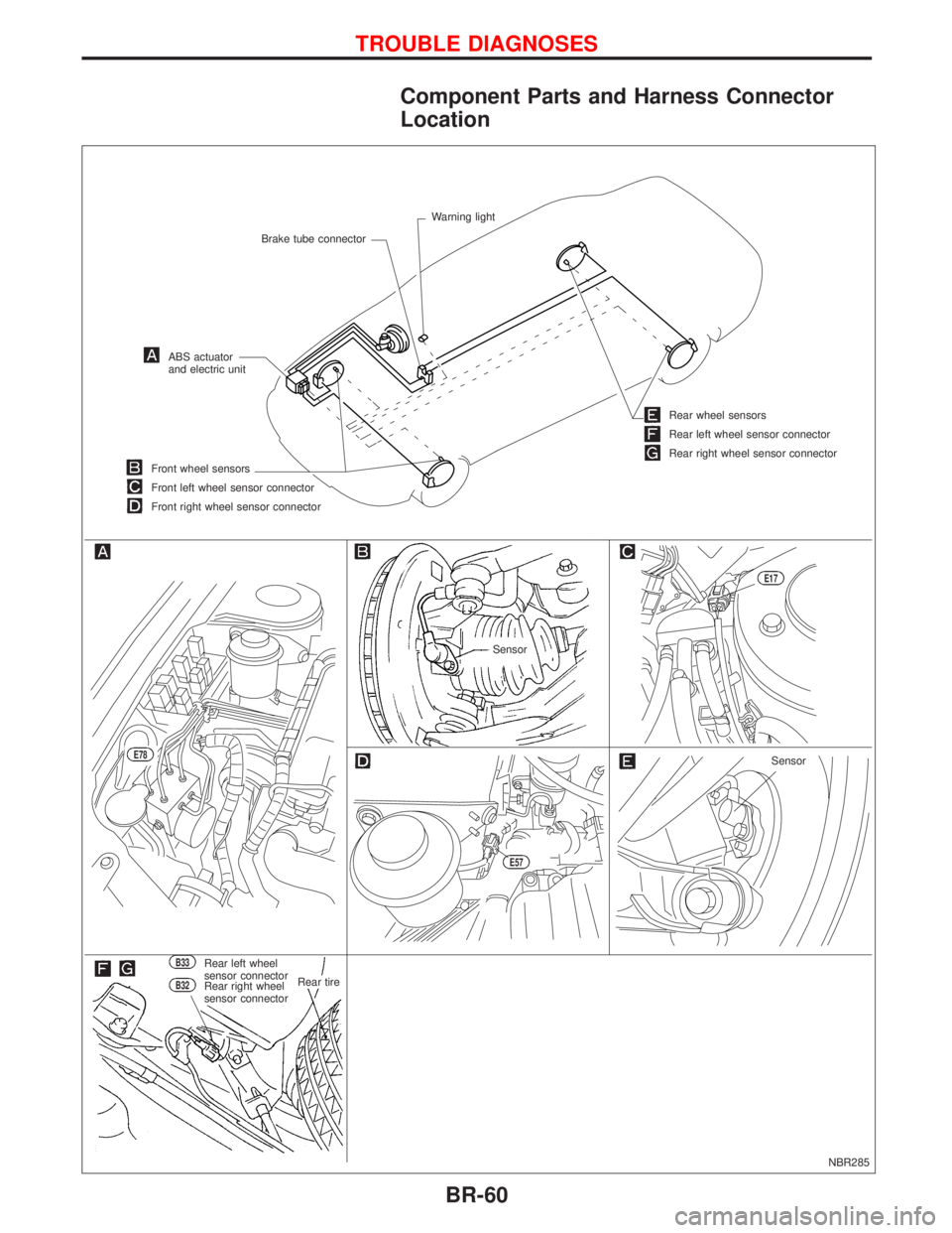
Component Parts and Harness Connector
Location
NBR285
Brake tube connectorWarning light
ABS actuator
and electric unit
Front wheel sensors
Front left wheel sensor connector
Front right wheel sensor connector
Sensor
E17
Rear wheel sensors
Rear left wheel sensor connector
Rear right wheel sensor connector
B33Rear left wheel
sensor connector
B32Rear right wheel
sensor connector.Rear tire
.E78
E57
Sensor
TROUBLE DIAGNOSES
BR-60
Page 195 of 2267
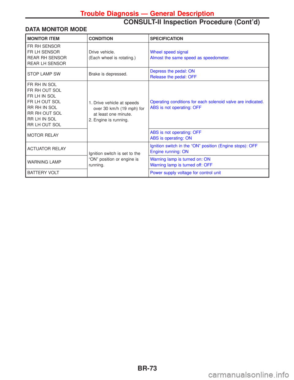
DATA MONITOR MODE
MONITOR ITEM CONDITION SPECIFICATION
FR RH SENSOR
FR LH SENSOR
REAR RH SENSOR
REAR LH SENSORDrive vehicle.
(Each wheel is rotating.)Wheel speed signal
Almost the same speed as speedometer.
STOP LAMP SW Brake is depressed.Depress the pedal: ON
Release the pedal: OFF
FR RH IN SOL
FR RH OUT SOL
FR LH IN SOL
FR LH OUT SOL
RR RH IN SOL
RR RH OUT SOL
RR LH IN SOL
RR LH OUT SOL1. Drive vehicle at speeds
over 30 km/h (19 mph) for
at least one minute.
2. Engine is running.Operating conditions for each solenoid valve are indicated.
ABS is not operating: OFF
MOTOR RELAYABS is not operating: OFF
ABS is operating: ON
ACTUATOR RELAY
Ignition switch is set to the
ªONº position or engine is
running.Ignition switch in the ªONº position (Engine stops): OFF
Engine running: ON
WARNING LAMPWarning lamp is turned on: ON
Warning lamp is turned off: OFF
BATTERY VOLTPower supply voltage for control unit
Trouble Diagnosis Ð General Description
CONSULT-II Inspection Procedure (Cont'd)
BR-73
Page 198 of 2267
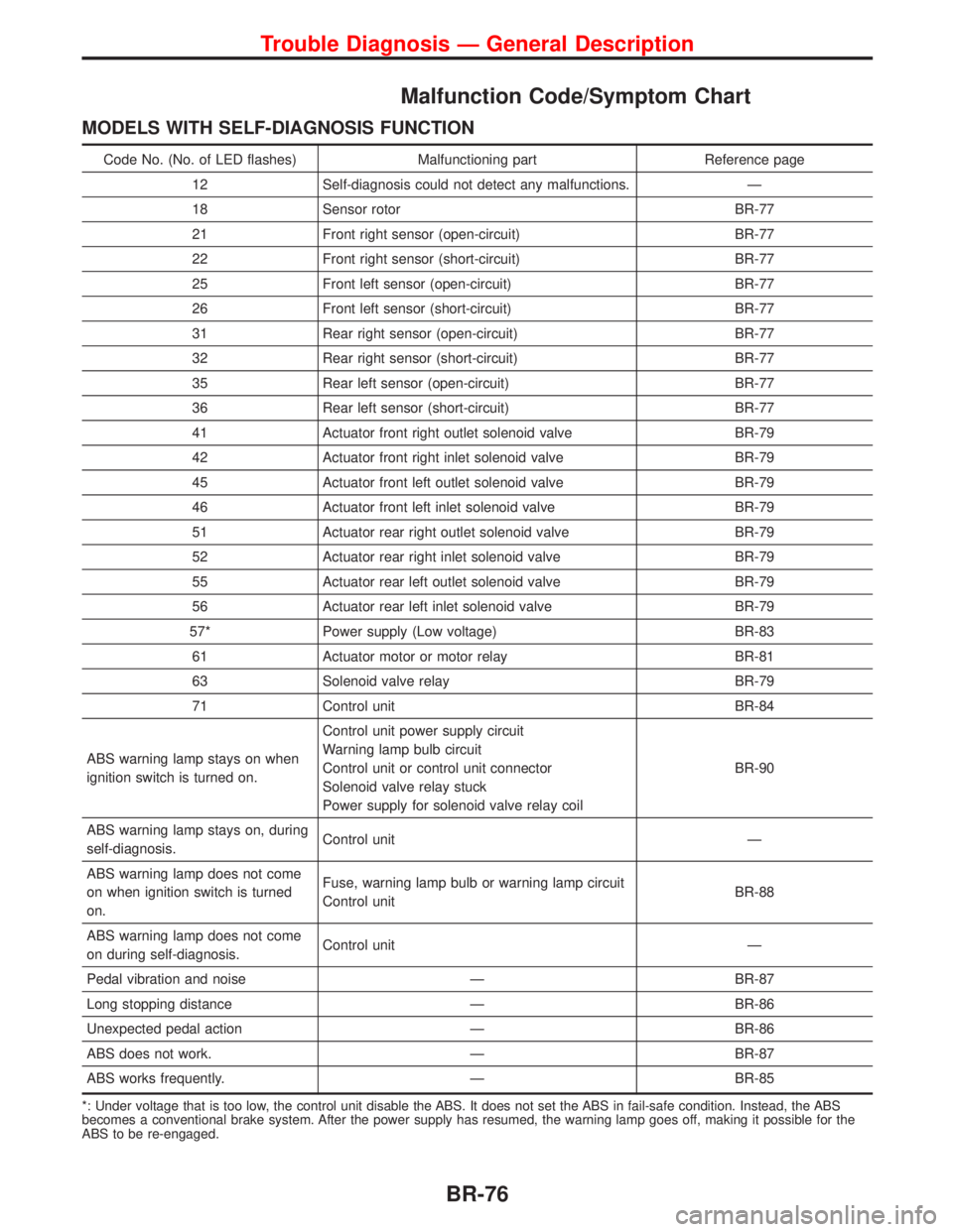
Malfunction Code/Symptom Chart
MODELS WITH SELF-DIAGNOSIS FUNCTION
Code No. (No. of LED flashes) Malfunctioning part Reference page
12 Self-diagnosis could not detect any malfunctions. Ð
18 Sensor rotor BR-77
21 Front right sensor (open-circuit) BR-77
22 Front right sensor (short-circuit) BR-77
25 Front left sensor (open-circuit) BR-77
26 Front left sensor (short-circuit) BR-77
31 Rear right sensor (open-circuit) BR-77
32 Rear right sensor (short-circuit) BR-77
35 Rear left sensor (open-circuit) BR-77
36 Rear left sensor (short-circuit) BR-77
41 Actuator front right outlet solenoid valve BR-79
42 Actuator front right inlet solenoid valve BR-79
45 Actuator front left outlet solenoid valve BR-79
46 Actuator front left inlet solenoid valve BR-79
51 Actuator rear right outlet solenoid valve BR-79
52 Actuator rear right inlet solenoid valve BR-79
55 Actuator rear left outlet solenoid valve BR-79
56 Actuator rear left inlet solenoid valve BR-79
57* Power supply (Low voltage) BR-83
61 Actuator motor or motor relay BR-81
63 Solenoid valve relay BR-79
71 Control unit BR-84
ABS warning lamp stays on when
ignition switch is turned on.Control unit power supply circuit
Warning lamp bulb circuit
Control unit or control unit connector
Solenoid valve relay stuck
Power supply for solenoid valve relay coilBR-90
ABS warning lamp stays on, during
self-diagnosis.Control unit Ð
ABS warning lamp does not come
on when ignition switch is turned
on.Fuse, warning lamp bulb or warning lamp circuit
Control unitBR-88
ABS warning lamp does not come
on during self-diagnosis.Control unit Ð
Pedal vibration and noise Ð BR-87
Long stopping distance Ð BR-86
Unexpected pedal action Ð BR-86
ABS does not work. Ð BR-87
ABS works frequently. Ð BR-85
*: Under voltage that is too low, the control unit disable the ABS. It does not set the ABS in fail-safe condition. Instead, the ABS
becomes a conventional brake system. After the power supply has resumed, the warning lamp goes off, making it possible for the
ABS to be re-engaged.
Trouble Diagnosis Ð General Description
BR-76
Page 208 of 2267
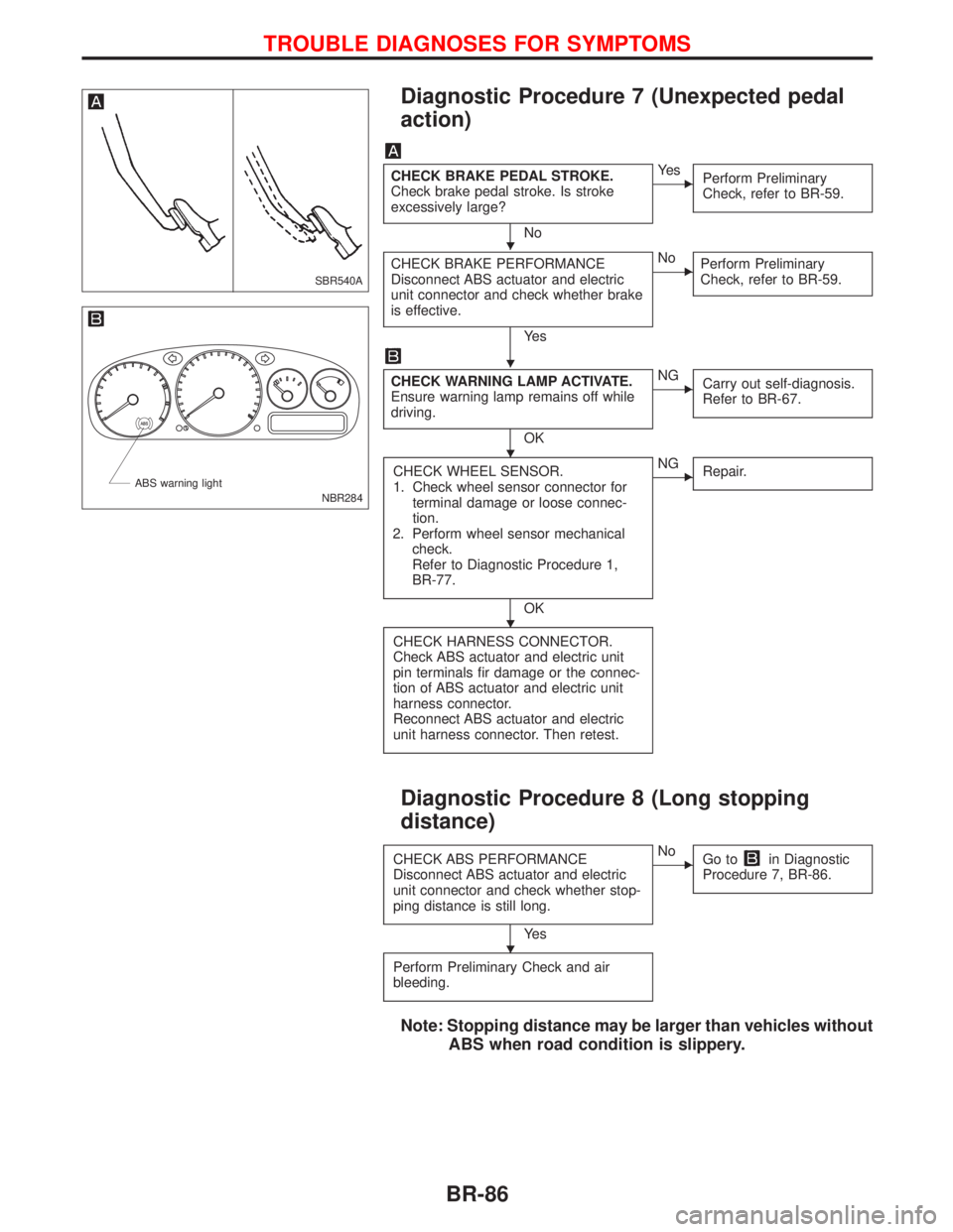
Diagnostic Procedure 7 (Unexpected pedal
action)
CHECK BRAKE PEDAL STROKE.
Check brake pedal stroke. Is stroke
excessively large?
No
EYe s
Perform Preliminary
Check, refer to BR-59.
CHECK BRAKE PERFORMANCE
Disconnect ABS actuator and electric
unit connector and check whether brake
is effective.
Ye s
ENo
Perform Preliminary
Check, refer to BR-59.
CHECK WARNING LAMP ACTIVATE.
Ensure warning lamp remains off while
driving.
OK
ENG
Carry out self-diagnosis.
Refer to BR-67.
CHECK WHEEL SENSOR.
1. Check wheel sensor connector for
terminal damage or loose connec-
tion.
2. Perform wheel sensor mechanical
check.
Refer to Diagnostic Procedure 1,
BR-77.
OK
ENG
Repair.
CHECK HARNESS CONNECTOR.
Check ABS actuator and electric unit
pin terminals fir damage or the connec-
tion of ABS actuator and electric unit
harness connector.
Reconnect ABS actuator and electric
unit harness connector. Then retest.
Diagnostic Procedure 8 (Long stopping
distance)
CHECK ABS PERFORMANCE
Disconnect ABS actuator and electric
unit connector and check whether stop-
ping distance is still long.
Ye s
ENo
Go toin Diagnostic
Procedure 7, BR-86.
Perform Preliminary Check and air
bleeding.
Note: Stopping distance may be larger than vehicles without
ABS when road condition is slippery.
SBR540A
NBR284 ABS warning light
H
H
H
H
H
TROUBLE DIAGNOSES FOR SYMPTOMS
BR-86
Page 209 of 2267
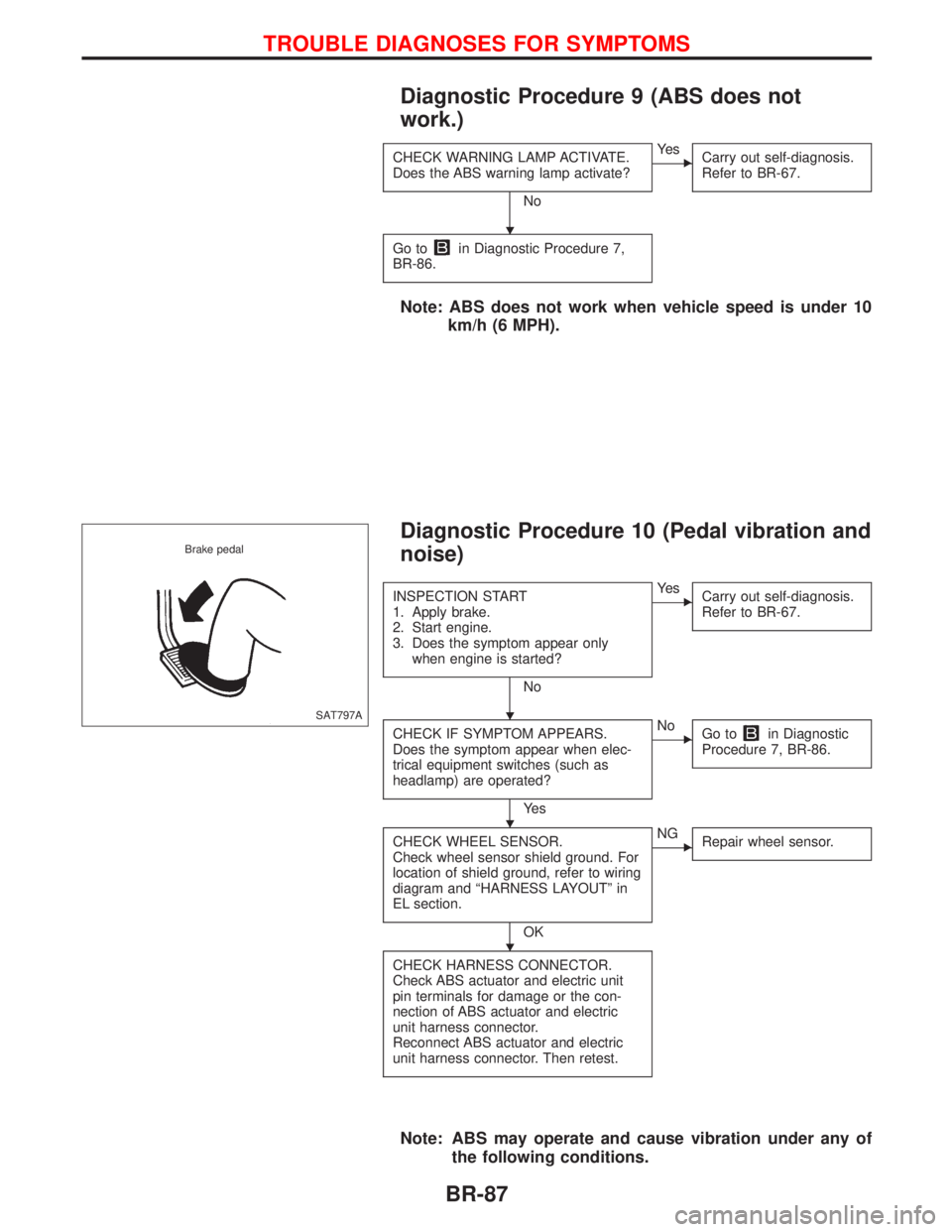
Diagnostic Procedure 9 (ABS does not
work.)
CHECK WARNING LAMP ACTIVATE.
Does the ABS warning lamp activate?
No
EYe s
Carry out self-diagnosis.
Refer to BR-67.
Go toin Diagnostic Procedure 7,
BR-86.
Note: ABS does not work when vehicle speed is under 10
km/h (6 MPH).
Diagnostic Procedure 10 (Pedal vibration and
noise)
INSPECTION START
1. Apply brake.
2. Start engine.
3. Does the symptom appear only
when engine is started?
No
EYe s
Carry out self-diagnosis.
Refer to BR-67.
CHECK IF SYMPTOM APPEARS.
Does the symptom appear when elec-
trical equipment switches (such as
headlamp) are operated?
Ye s
ENo
Go toin Diagnostic
Procedure 7, BR-86.
CHECK WHEEL SENSOR.
Check wheel sensor shield ground. For
location of shield ground, refer to wiring
diagram and ªHARNESS LAYOUTº in
EL section.
OK
ENG
Repair wheel sensor.
CHECK HARNESS CONNECTOR.
Check ABS actuator and electric unit
pin terminals for damage or the con-
nection of ABS actuator and electric
unit harness connector.
Reconnect ABS actuator and electric
unit harness connector. Then retest.
Note: ABS may operate and cause vibration under any of
the following conditions.
SAT797A Brake pedal
H
H
H
H
TROUBLE DIAGNOSES FOR SYMPTOMS
BR-87
Page 296 of 2267
Injection Timing Control Valve ................................. 82
TROUBLE DIAGNOSIS 7............................................ 86
Engine Control Module (ECM) ................................ 86
TROUBLE DIAGNOSIS 8............................................ 87
Cooling Fan (Overheat) ........................................... 87
TROUBLE DIAGNOSIS 9............................................ 97
Needle Lift Sensor (NLS) ........................................ 97
TROUBLE DIAGNOSIS 10........................................ 100
Fuel Cut Solenoid Valve ........................................ 100
TROUBLE DIAGNOSIS 11........................................ 104
Fuel Temperature Sensor (FTS)............................ 104
TROUBLE DIAGNOSIS 12........................................ 108
Accelerator Position Sensor & Switch ................... 108
TROUBLE DIAGNOSIS 13......................................... 114
Crankshaft Position Sensor (TDC) ......................... 114
TROUBLE DIAGNOSES 14....................................... 118
Glow Control System .............................................. 118TROUBLE DIAGNOSES 15...................................... 126
Air Conditioner Cut Control ................................... 126
TROUBLE DIAGNOSES 16...................................... 129
EGRC-Solenoid Valve ........................................... 129
TROUBLE DIAGNOSES 17...................................... 136
Brake Switch .......................................................... 136
TROUBLE DIAGNOSES 18...................................... 140
ECM Relay............................................................. 140
TROUBLE DIAGNOSES 19...................................... 141
MI & Data Link Connectors ................................... 141
TROUBLE DIAGNOSES 20...................................... 145
Start Signal ............................................................ 145
SERVICE DATA AND SPECIFICATIONS (SDS)...... 147
General Specifications ........................................... 147
Injection Nozzle ..................................................... 147
Inspection and Adjustment .................................... 147
When you read wiring diagrams:
lRead GI section, ªHOW TO READ WIRING DIAGRAMSº.
lSee EL section, ªPOWER SUPPLY ROUTINGº for power distribution circuit.
lSee EL section for NATS information and wiring diagram.
When you perform trouble diagnoses, read GI section, ªHOW TO FOLLOW FLOW CHART
IN TROUBLE DIAGNOSESº and ªHOW TO PERFORM EFFICIENT DIAGNOSIS FOR AN
ELECTRICAL INCIDENTº.
For clarification of system component abbreviations and terminology read GI section
ªSAE J1930 TERMINOLOGY LISTº.
EC-2