1999 NISSAN PRIMERA brake sensor
[x] Cancel search: brake sensorPage 308 of 2267
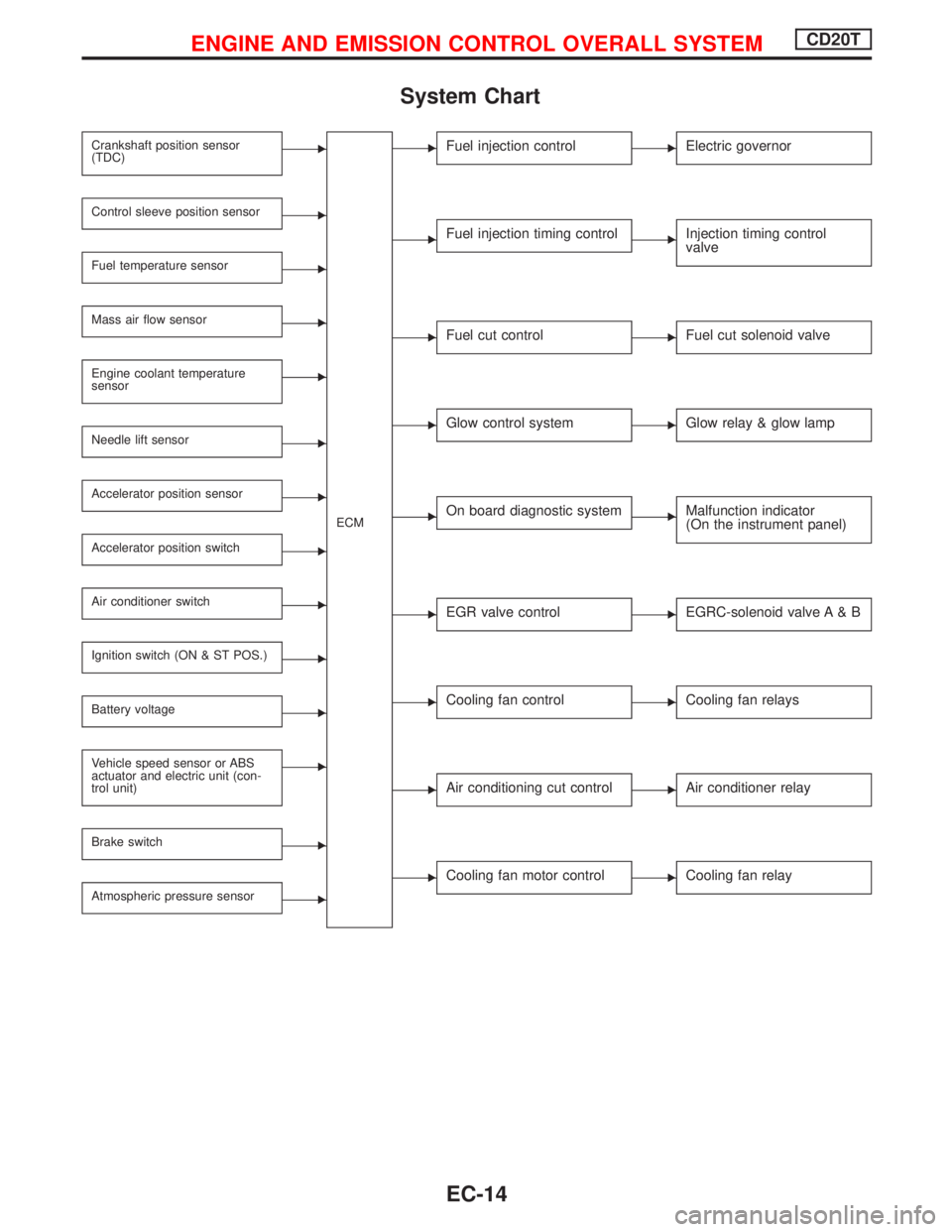
System Chart
Crankshaft position sensor
(TDC)E
ECM
Control sleeve position sensorE
Fuel temperature sensorE
Mass air flow sensorE
Engine coolant temperature
sensorE
Needle lift sensorE
Accelerator position sensorE
Accelerator position switchE
Air conditioner switchE
Ignition switch (ON & ST POS.)E
Battery voltageE
Vehicle speed sensor or ABS
actuator and electric unit (con-
trol unit)E
Brake switchE
Atmospheric pressure sensorE
EFuel injection controlEElectric governor
EFuel injection timing controlEInjection timing control
valve
EFuel cut controlEFuel cut solenoid valve
EGlow control systemEGlow relay & glow lamp
EOn board diagnostic systemEMalfunction indicator
(On the instrument panel)
EEGR valve controlEEGRC-solenoid valve A & B
ECooling fan controlECooling fan relays
EAir conditioning cut controlEAir conditioner relay
ECooling fan motor controlECooling fan relay
ENGINE AND EMISSION CONTROL OVERALL SYSTEMCD20T
EC-14
Page 322 of 2267
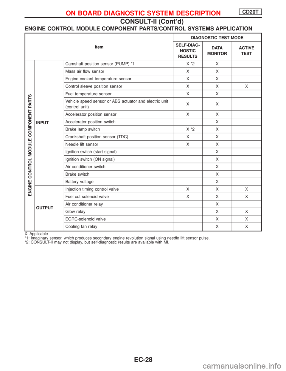
ENGINE CONTROL MODULE COMPONENT PARTS/CONTROL SYSTEMS APPLICATION
ItemDIAGNOSTIC TEST MODE
SELF-DIAG-
NOSTIC
RESULTSD ATA
MONITORACTIVE
TEST
ENGINE CONTROL MODULE COMPONENT PARTS
INPUTCamshaft position sensor (PUMP) *1 X *2 X
Mass air flow sensor X X
Engine coolant temperature sensor X X
Control sleeve position sensor X X X
Fuel temperature sensor X X
Vehicle speed sensor or ABS actuator and electric unit
(control unit)XX
Accelerator position sensor X X
Accelerator position switch X
Brake lamp switch X *2 X
Crankshaft position sensor (TDC) X X
Needle lift sensor X X
Ignition switch (start signal) X
Ignition switch (ON signal) X
Air conditioner switch X
Brake switch X
Battery voltage X
OUTPUTInjection timing control valve X X X
Fuel cut solenoid valve X X X
Air conditioner relay X
Glow relay X X
EGRC-solenoid valve X X
Cooling fan relay X X
X: Applicable
*1: Imaginary sensor, which produces secondary engine revolution signal using needle lift sensor pulse.
*2: CONSULT-II may not display, but self-diagnostic results are available with MI.
ON BOARD DIAGNOSTIC SYSTEM DESCRIPTIONCD20T
CONSULT-II (Cont'd)
EC-28
Page 323 of 2267
![NISSAN PRIMERA 1999 Electronic Repair Manual SELF-DIAGNOSTIC MODE
Regarding items detected in ªSELF-DIAG RESULTSº mode, refer to ªDiagnostic Trouble chartº.
DATA MONITOR MODE
Monitored item
[Unit]ECM
input
signalsMain
signalsDescription Rema NISSAN PRIMERA 1999 Electronic Repair Manual SELF-DIAGNOSTIC MODE
Regarding items detected in ªSELF-DIAG RESULTSº mode, refer to ªDiagnostic Trouble chartº.
DATA MONITOR MODE
Monitored item
[Unit]ECM
input
signalsMain
signalsDescription Rema](/manual-img/5/57377/w960_57377-322.png)
SELF-DIAGNOSTIC MODE
Regarding items detected in ªSELF-DIAG RESULTSº mode, refer to ªDiagnostic Trouble chartº.
DATA MONITOR MODE
Monitored item
[Unit]ECM
input
signalsMain
signalsDescription Remarks
CKPS×RPM
(TDC) [rpm]
qq
lThe engine speed computed from the
crankshaft position sensor (TDC) sig-
nal is displayed.
CMPS×RPM -
PUMP [rpm]
qq
lThe engine speed computed from the
camshaft position sensor (PUMP) sig-
nal is displayed.
COOLAN TEMP/S
[ÉC] or [ÉF]
qq
lThe engine coolant temperature (deter-
mined by the signal voltage of the
engine coolant temperature sensor) is
displayed.lWhen the engine coolant temperature
sensor is open or short-circuited, ECM
enters fail-safe mode. The engine cool-
ant temperature determined by the
ECM is displayed.
VHCL SPEED SE
[km/h] or [mph]
qq
lThe vehicle speed computed from the
vehicle speed sensor signal or ABS
actuator and electric unit (control unit)
signal is displayed.
FUEL TEMP SEN
[ÉC] or [ÉF]
qq
lThe fuel temperature (determined by
the signal voltage of the fuel tempera-
ture sensor) is displayed.
ACCEL POS SEN
[V]
qqlThe accelerator position sensor signal
voltage is displayed.
OFF ACCEL POS
[ON/OFF]
qqlIndicates [ON/OFF] condition from the
accelerator position switch signal.
C/SLEEV POS/S [V]
qqlThe control sleeve position sensor sig-
nal voltage is displayed.
BATTERY VOLT [V]
qqlThe power supply voltage of ECM is
displayed.
START SIGNAL
[ON/OFF]
qqlIndicates [ON/OFF] condition from the
starter signal.lAfter starting the engine, [OFF] is dis-
played regardless of the starter signal.
AIR COND SIG
[ON/OFF]
qq
lIndicates [ON/OFF] condition of the air
conditioner switch as determined by
the air conditioner signal.
BRAKE SW
[ON/OFF]
qlIndicates [ON/OFF] condition of the
stio lamp switch.
BRAKE SW2
[ON/OFF]
qlIndicates [ON/OFF] condition of the
stio lamp switch 2.
IGN SW
[ON/OFF]
qqlIndicates [ON/OFF] condition from igni-
tion switch.
MAS AIR/FL SE [V]
qqlThe signal voltage of the mass air flow
sensor is displayed.lWhen the engine is stopped, a certain
value is indicated.
ACT INJ TIMG [É]
q
lThe actual injection timing angle deter-
mined by the ECM (an approximate
average angle between injection start
and end from TDC) is displayed.
TARGET F/INJ
[mm
3/STROKE]q
lThe target fuel injection quantity
(determined by the ECM according to
the input signal) is indicated.
NOTE:
Any monitored item that does not match the vehicle being diagnosed is deleted from the display automatically.
ON BOARD DIAGNOSTIC SYSTEM DESCRIPTIONCD20T
CONSULT-II (Cont'd)
EC-29
Page 337 of 2267
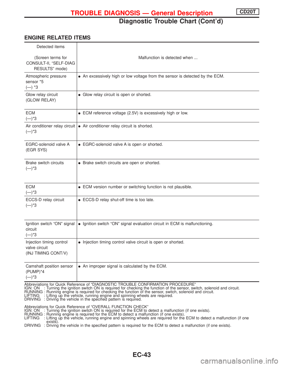
ENGINE RELATED ITEMS
Detected items
(Screen terms for
CONSULT-II, ªSELF-DIAG
RESULTSº mode)Malfunction is detected when ...
Atmospheric pressure
sensor *5
(Ð) *3
lAn excessively high or low voltage from the sensor is detected by the ECM.
Glow relay circuit
(GLOW RELAY)
lGlow relay circuit is open or shorted.
ECM
(Ð)*3
lECM reference voltage (2.5V) is excessively high or low.
Air conditioner relay circuit
(Ð)*3
lAir conditioner relay circuit is shorted.
EGRC-solenoid valve A
(EGR SYS)
lEGRC-solenoid valve A is open or shorted.
Brake switch circuits
(Ð)*3
lBrake switch circuits are open or shorted.
ECM
(Ð)*3
lECM version number or switching function is not plausible.
ECCS-D relay circuit
(Ð)*3
lECCS-D relay shut-off time is too late.
Ignition switch ªONº signal
circuit
(Ð)*3
lIgnition switch ªONº signal evaluation circuit in ECM is malfunctioning.
Injection timing control
valve circuit
(INJ TIMING CONT/V)
lInjection timing control valve circuit is open or shorted.
Camshaft position sensor
(PUMP)*4
(Ð)*3
lAn improper signal is calculated by the ECM.
Abbreviations for Quick Reference of ªDIAGNOSTIC TROUBLE CONFIRMATION PROCEDUREº
IGN: ON : Turning the ignition switch ON is required for checking the function of the sensor, switch, solenoid and circuit.
RUNNING : Running engine is required for checking the function of the sensor, switch, solenoid and circuit.
LIFTING : Lifting up the vehicle, running engine and spinning wheels are required.
DRIVING : Driving the vehicle in the specified pattern is required.
Abbreviations for Quick Reference of ªOVERALL FUNCTION CHECKº
IGN: ON : Turning the ignition switch ON is required for the ECM to detect a malfunction (if one exists).
RUNNING : Running engine is required for the ECM to detect a malfunction (if one exists).
LIFTING : Lifting up the vehicle, running engine and spinning wheels are required for the ECM to detect a malfunction (if one
exists).
DRIVING : Driving the vehicle in the specified pattern is required for the ECM to detect a malfunction (if one exists).
TROUBLE DIAGNOSIS Ð General DescriptionCD20T
Diagnostic Trouble Chart (Cont'd)
EC-43
Page 338 of 2267
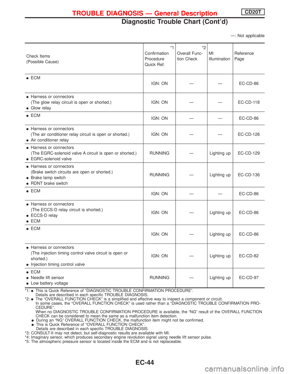
Ð: Not applicable
Check Items
(Possible Cause)*1
Confirmation
Procedure
Quick Ref.*2
Overall Func-
tion CheckMI
IlluminationReference
Page
lECM
IGN: ON Ð Ð EC-CD-86
lHarness or connectors
(The glow relay circuit is open or shorted.)
lGlow relayIGN: ON Ð Ð EC-CD-118
lECM
IGN: ON Ð Ð EC-CD-86
lHarness or connectors
(The air conditioner relay circuit is open or shorted.)
lAir conditioner relayIGN: ON Ð Ð EC-CD-126
lHarness or connectors
(The EGRC-solenoid valve A circuit is open or shorted.)
lEGRC-solenoid valveRUNNING Ð Lighting up EC-CD-129
lHarness or connectors
(Brake switch circuits are open or shorted.)
lBrake lamp switch
lRDNT brake switchRUNNING Ð Lighting up EC-CD-136
lECM
IGN: ON Ð Ð EC-CD-86
lHarness or connectors
(The ECCS-D relay circuit is shorted.)
lECCS-D relay
lECMIGN: ON Ð Lighting up EC-CD-86
lECM
IGN: ON Ð Lighting up EC-CD-86
lHarness or connectors
(The injection timing control valve circuit is open or
shorted.)
lInjection timing control valveIGN: ON Ð Lighting up EC-CD-82
lECM
lNeedle lift sensor
lLow battery voltageRUNNING Ð Lighting up EC-CD-97
*1:lThis is Quick Reference of ªDIAGNOSTIC TROUBLE CONFIRMATION PROCEDUREº.
Details are described in each specific TROUBLE DIAGNOSIS.
*2:
lThe ªOVERALL FUNCTION CHECKº is a simplified and effective way to inspect a component or circuit.
In some cases, the ªOVERALL FUNCTION CHECKº is used rather than a ªDIAGNOSTIC TROUBLE CONFIRMATION PRO-
CEDUREº.
When no DIAGNOSTIC TROUBLE CONFIRMATION PROCEDURE is available, the ªNGº result of the OVERALL FUNCTION
CHECK can be considered to mean the same as a malfunction item detection.
lDuring an ªNGº OVERALL FUNCTION CHECK, the malfunction item might not be confirmed.lThis is Quick Reference of ªOVERALL FUNCTION CHECKº.
Details are described in each specific TROUBLE DIAGNOSIS.
*3: CONSULT-II may not detect, but self-diagnostic results are available with MI.
*4: Imaginary sensor, which produces secondary engine revolution signal using needle lift sensor pulse.
*5: The atmospheric pressure sensor is located inside the ECM and is not replaceable.
TROUBLE DIAGNOSIS Ð General DescriptionCD20T
Diagnostic Trouble Chart (Cont'd)
EC-44
Page 343 of 2267
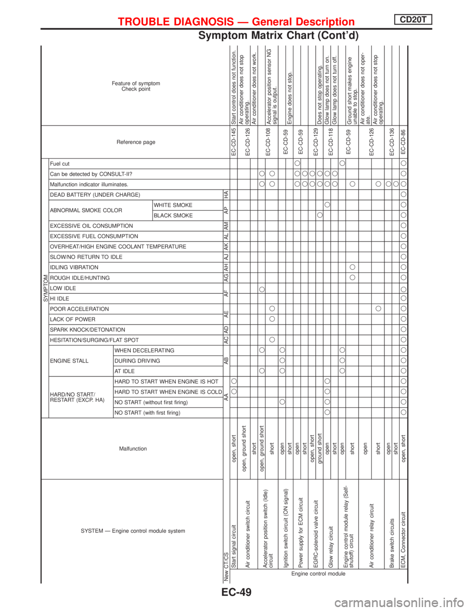
SYSTEM Ð Engine control module systemMalfunction
SYMPTOM
Reference page Feature of symptom
Check point
HARD/NO START/
RESTART (EXCP. HA) ENGINE STALL HESITATION/SURGING/FLAT SPOT SPARK KNOCK/DETONATION
LACK OF POWER
POOR ACCELERATION
HI IDLE
LOW IDLE
ROUGH IDLE/HUNTING
IDLING VIBRATION
SLOW/NO RETURN TO IDLE
OVERHEAT/HIGH ENGINE COOLANT TEMPERATURE
EXCESSIVE FUEL CONSUMPTION
EXCESSIVE OIL CONSUMPTION ABNORMAL SMOKE COLOR
DEAD BATTERY (UNDER CHARGE) Malfunction indicator illuminates.
Can be detected by CONSULT-II?
Fuel cut
NO START (with first firing) NO START (without first firing)
HARD TO START WHEN ENGINE IS COLD
HARD TO START WHEN ENGINE IS HOT
AT IDLE
DURING DRIVING
WHEN DECELERATINGBLACK SMOKE WHITE SMOKE
New CT/CS AA AB AC AD AE AF AG AH AJ AK AL AM AP HAEngine control moduleStart signal circuit open, shortqqEC-CD-145 Start control does not function.
Air conditioner switch circuitopen, ground short
EC-CD-126Air conditioner does not stop
operating.
shortAir conditioner does not work.
Accelerator position switch (Idle)
circuitopen, ground shortqq q qq
EC-CD-108
shortqqq qqAccelerator position sensor NG
signal is output.
Ignition switch circuit (ON signal)openq qqq
EC-CD-59
shortEngine does not stop.
Power supply for ECM circuitopenqqq
EC-CD-59
shortqq
EGRC-solenoid valve circuitopen, shortqq
EC-CD-129
ground shortqqqDoes not stop operating.
Glow relay circuitopenqqqq q qq
EC-CD-118Glow lamp does not turn on.
shortqqGlow lamp does not turn off.
Engine control module relay (Self-
shutoff) circuitopenqqqq
EC-CD-59
shortqq qGround short makes engine
unable to stop.
Air conditioner relay circuitopen
EC-CD-126Air conditioner does not oper-
ate.
shortqqAir conditioner does not stop
operating.
Brake switch circuitsopenq
EC-CD-136
shortq
ECM, Connector circuit open, shortqqqqqqqqqqqqq qqqqqqqqqqqqEC-CD-86
TROUBLE DIAGNOSIS Ð General DescriptionCD20T
Symptom Matrix Chart (Cont'd)
EC-49
Page 351 of 2267
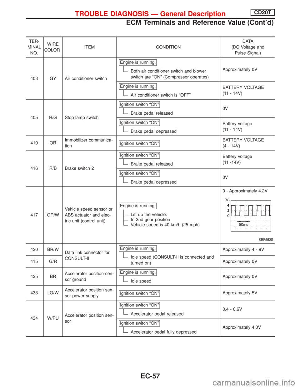
TER-
MINAL
NO.WIRE
COLORITEM CONDITIOND ATA
(DC Voltage and
Pulse Signal)
403 GY Air conditioner switchEngine is running.
Both air conditioner switch and blower
switch are ªONº (Compressor operates)Approximately 0V
Engine is running.
Air conditioner switch is ªOFFºBATTERY VOLTAGE
(11 - 14V)
405 R/G Stop lamp switchIgnition switch ªONº
Brake pedal released0V
Ignition switch ªONº
Brake pedal depressedBattery voltage
(11 - 14V)
410 ORImmobilizer communica-
tionIgnition switch ªONº
BATTERY VOLTAGE
(4 - 14V)
416 R/B Brake switch 2Ignition switch ªONº
Brake pedal releasedBattery voltage
(11 -14V)
Ignition switch ªONº
Brake pedal depressed0V
417 OR/WVehicle speed sensor or
ABS actuator and elec-
tric unit (control unit)Engine is running.
Lift up the vehicle.
In 2nd gear position
Vehicle speed is 40 km/h (25 mph)0 - Approximately 4.2V
SEF552S
420 BR/W
Data link connector for
CONSULT-IIEngine is running.
Idle speed (CONSULT-II is connected and
turned on)Approximately4-9V
415 G/RApproximately 0V
425 BRAccelerator position sen-
sor groundEngine is running.
Idle speedApproximately 0V
433 LG/WAccelerator position sen-
sor power supplyIgnition switch ªONº
Approximately 5V
434 W/PUAccelerator position sen-
sorIgnition switch ªONº
Accelerator pedal released0.4 - 0.6V
Ignition switch ªONº
Accelerator pedal fully depressedApproximately 4.0V
TROUBLE DIAGNOSIS Ð General DescriptionCD20T
ECM Terminals and Reference Value (Cont'd)
EC-57
Page 402 of 2267
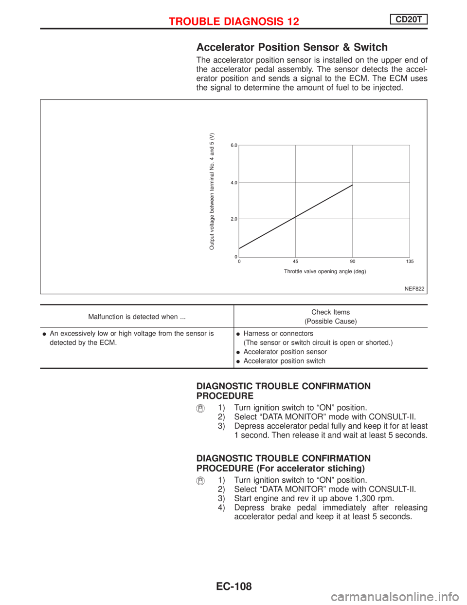
Accelerator Position Sensor & Switch
The accelerator position sensor is installed on the upper end of
the accelerator pedal assembly. The sensor detects the accel-
erator position and sends a signal to the ECM. The ECM uses
the signal to determine the amount of fuel to be injected.
Malfunction is detected when ...Check Items
(Possible Cause)
lAn excessively low or high voltage from the sensor is
detected by the ECM.lHarness or connectors
(The sensor or switch circuit is open or shorted.)
lAccelerator position sensor
lAccelerator position switch
DIAGNOSTIC TROUBLE CONFIRMATION
PROCEDURE
1) Turn ignition switch to ªONº position.
2) Select ªDATA MONITORº mode with CONSULT-II.
3) Depress accelerator pedal fully and keep it for at least
1 second. Then release it and wait at least 5 seconds.
DIAGNOSTIC TROUBLE CONFIRMATION
PROCEDURE (For accelerator stiching)
1) Turn ignition switch to ªONº position.
2) Select ªDATA MONITORº mode with CONSULT-II.
3) Start engine and rev it up above 1,300 rpm.
4) Depress brake pedal immediately after releasing
accelerator pedal and keep it at least 5 seconds.
NEF822
Output voltage between terminal No. 4 and 5 (V)
Throttle valve opening angle (deg)
TROUBLE DIAGNOSIS 12CD20T
EC-108