1999 NISSAN PRIMERA check engine light
[x] Cancel search: check engine lightPage 338 of 2267
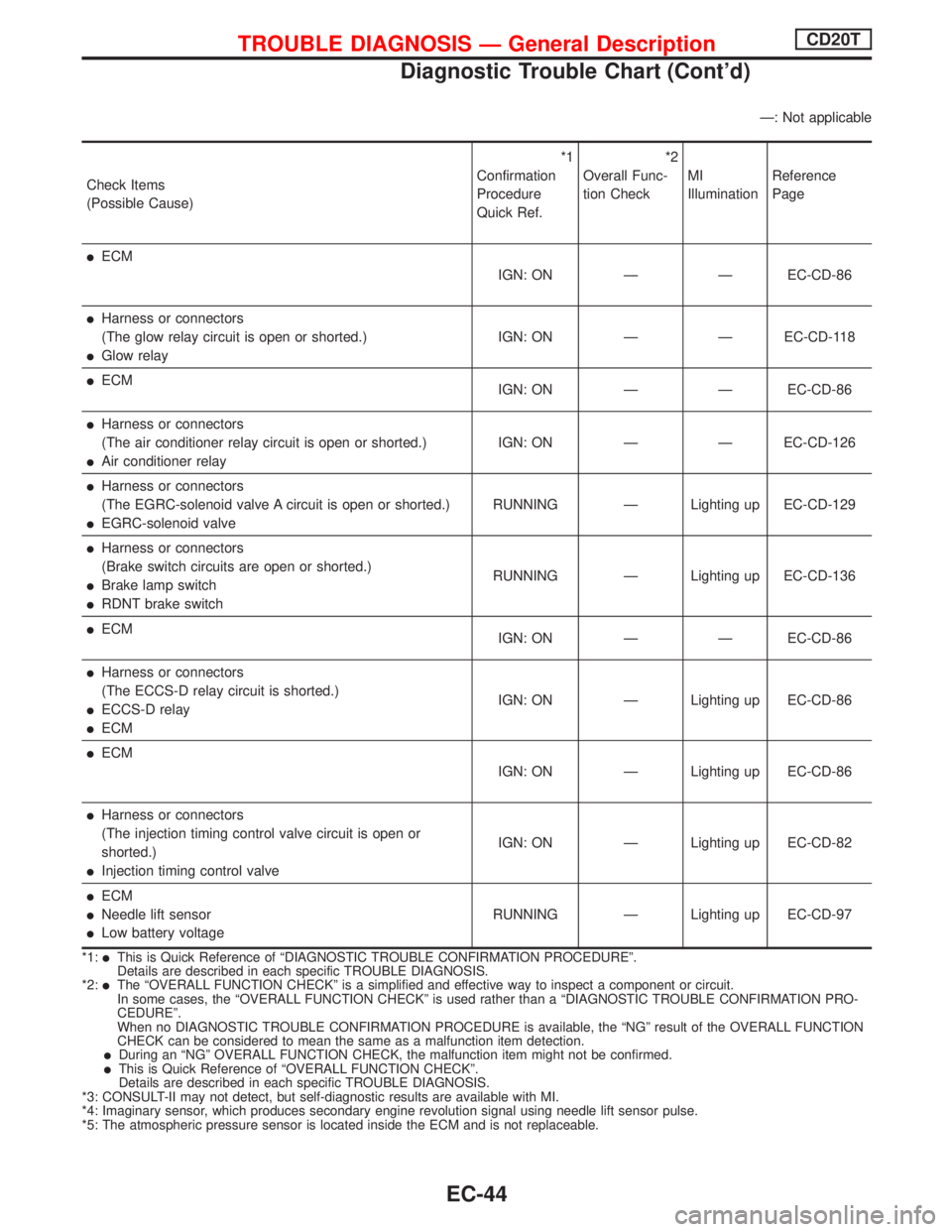
Ð: Not applicable
Check Items
(Possible Cause)*1
Confirmation
Procedure
Quick Ref.*2
Overall Func-
tion CheckMI
IlluminationReference
Page
lECM
IGN: ON Ð Ð EC-CD-86
lHarness or connectors
(The glow relay circuit is open or shorted.)
lGlow relayIGN: ON Ð Ð EC-CD-118
lECM
IGN: ON Ð Ð EC-CD-86
lHarness or connectors
(The air conditioner relay circuit is open or shorted.)
lAir conditioner relayIGN: ON Ð Ð EC-CD-126
lHarness or connectors
(The EGRC-solenoid valve A circuit is open or shorted.)
lEGRC-solenoid valveRUNNING Ð Lighting up EC-CD-129
lHarness or connectors
(Brake switch circuits are open or shorted.)
lBrake lamp switch
lRDNT brake switchRUNNING Ð Lighting up EC-CD-136
lECM
IGN: ON Ð Ð EC-CD-86
lHarness or connectors
(The ECCS-D relay circuit is shorted.)
lECCS-D relay
lECMIGN: ON Ð Lighting up EC-CD-86
lECM
IGN: ON Ð Lighting up EC-CD-86
lHarness or connectors
(The injection timing control valve circuit is open or
shorted.)
lInjection timing control valveIGN: ON Ð Lighting up EC-CD-82
lECM
lNeedle lift sensor
lLow battery voltageRUNNING Ð Lighting up EC-CD-97
*1:lThis is Quick Reference of ªDIAGNOSTIC TROUBLE CONFIRMATION PROCEDUREº.
Details are described in each specific TROUBLE DIAGNOSIS.
*2:
lThe ªOVERALL FUNCTION CHECKº is a simplified and effective way to inspect a component or circuit.
In some cases, the ªOVERALL FUNCTION CHECKº is used rather than a ªDIAGNOSTIC TROUBLE CONFIRMATION PRO-
CEDUREº.
When no DIAGNOSTIC TROUBLE CONFIRMATION PROCEDURE is available, the ªNGº result of the OVERALL FUNCTION
CHECK can be considered to mean the same as a malfunction item detection.
lDuring an ªNGº OVERALL FUNCTION CHECK, the malfunction item might not be confirmed.lThis is Quick Reference of ªOVERALL FUNCTION CHECKº.
Details are described in each specific TROUBLE DIAGNOSIS.
*3: CONSULT-II may not detect, but self-diagnostic results are available with MI.
*4: Imaginary sensor, which produces secondary engine revolution signal using needle lift sensor pulse.
*5: The atmospheric pressure sensor is located inside the ECM and is not replaceable.
TROUBLE DIAGNOSIS Ð General DescriptionCD20T
Diagnostic Trouble Chart (Cont'd)
EC-44
Page 475 of 2267
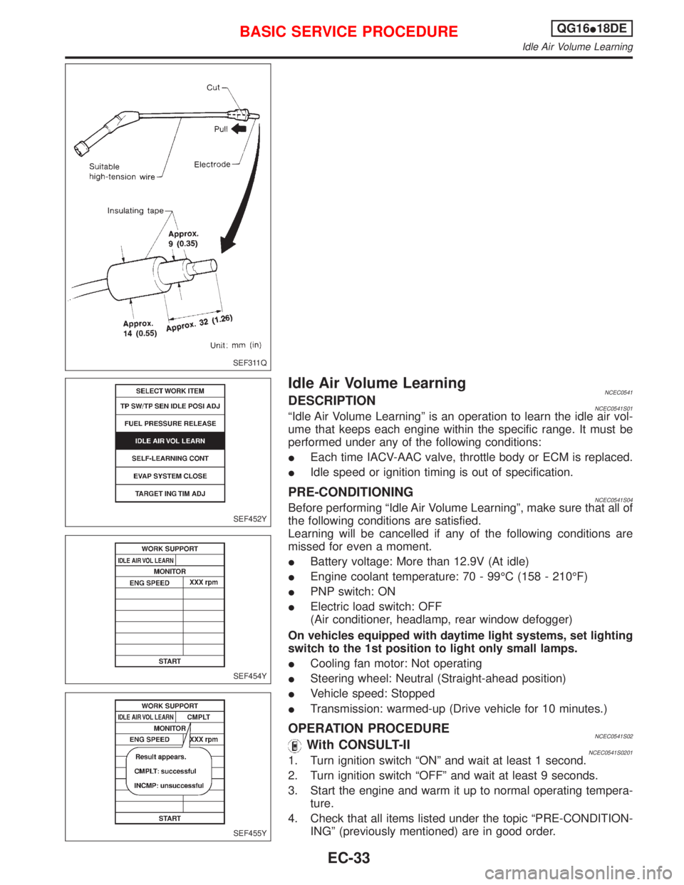
Idle Air Volume LearningNCEC0541DESCRIPTIONNCEC0541S01ªIdle Air Volume Learningº is an operation to learn the idle air vol-
ume that keeps each engine within the specific range. It must be
performed under any of the following conditions:
IEach time IACV-AAC valve, throttle body or ECM is replaced.
IIdle speed or ignition timing is out of specification.
PRE-CONDITIONINGNCEC0541S04Before performing ªIdle Air Volume Learningº, make sure that all of
the following conditions are satisfied.
Learning will be cancelled if any of the following conditions are
missed for even a moment.
IBattery voltage: More than 12.9V (At idle)
IEngine coolant temperature: 70 - 99ÉC (158 - 210ÉF)
IPNP switch: ON
IElectric load switch: OFF
(Air conditioner, headlamp, rear window defogger)
On vehicles equipped with daytime light systems, set lighting
switch to the 1st position to light only small lamps.
ICooling fan motor: Not operating
ISteering wheel: Neutral (Straight-ahead position)
IVehicle speed: Stopped
ITransmission: warmed-up (Drive vehicle for 10 minutes.)
OPERATION PROCEDURENCEC0541S02With CONSULT-IINCEC0541S02011. Turn ignition switch ªONº and wait at least 1 second.
2. Turn ignition switch ªOFFº and wait at least 9 seconds.
3. Start the engine and warm it up to normal operating tempera-
ture.
4. Check that all items listed under the topic ªPRE-CONDITION-
INGº (previously mentioned) are in good order.
SEF311Q
SEF452Y
SEF454Y
SEF455Y
BASIC SERVICE PROCEDUREQG16I18DE
Idle Air Volume Learning
EC-33
Page 478 of 2267
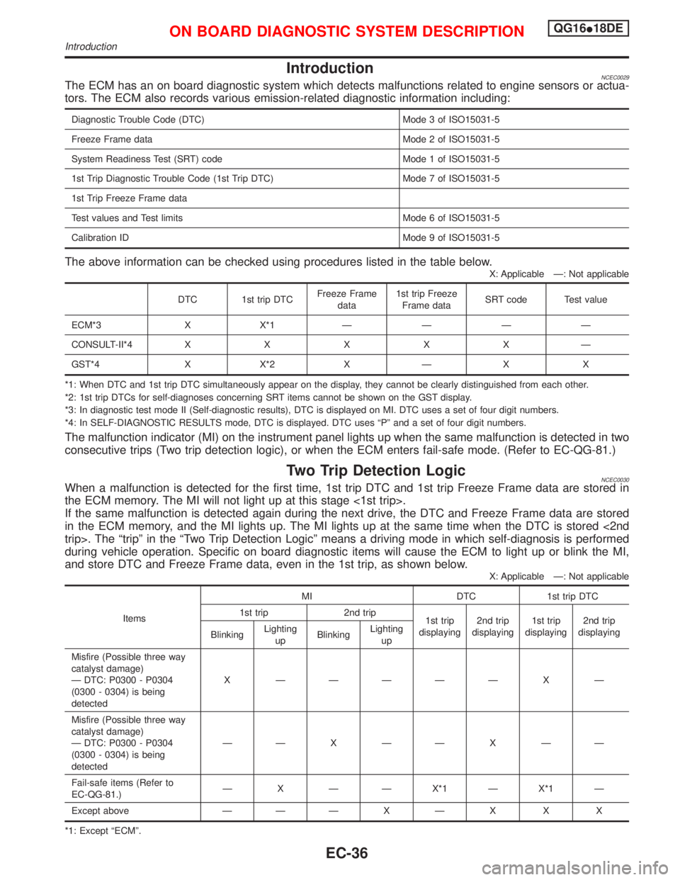
IntroductionNCEC0029The ECM has an on board diagnostic system which detects malfunctions related to engine sensors or actua-
tors. The ECM also records various emission-related diagnostic information including:
Diagnostic Trouble Code (DTC) Mode 3 of ISO15031-5
Freeze Frame data Mode 2 of ISO15031-5
System Readiness Test (SRT) code Mode 1 of ISO15031-5
1st Trip Diagnostic Trouble Code (1st Trip DTC) Mode 7 of ISO15031-5
1st Trip Freeze Frame data
Test values and Test limits Mode 6 of ISO15031-5
Calibration ID Mode 9 of ISO15031-5
The above information can be checked using procedures listed in the table below.
X: Applicable Ð: Not applicable
DTC 1st trip DTCFreeze Frame
data1st trip Freeze
Frame dataSRT code Test value
ECM*3 X X*1ÐÐÐÐ
CONSULT-II*4XXXXXÐ
GST*4 X X*2 X Ð X X
*1: When DTC and 1st trip DTC simultaneously appear on the display, they cannot be clearly distinguished from each other.
*2: 1st trip DTCs for self-diagnoses concerning SRT items cannot be shown on the GST display.
*3: In diagnostic test mode II (Self-diagnostic results), DTC is displayed on MI. DTC uses a set of four digit numbers.
*4: In SELF-DIAGNOSTIC RESULTS mode, DTC is displayed. DTC uses ªPº and a set of four digit numbers.
The malfunction indicator (MI) on the instrument panel lights up when the same malfunction is detected in two
consecutive trips (Two trip detection logic), or when the ECM enters fail-safe mode. (Refer to EC-QG-81.)
Two Trip Detection LogicNCEC0030When a malfunction is detected for the first time, 1st trip DTC and 1st trip Freeze Frame data are stored in
the ECM memory. The MI will not light up at this stage <1st trip>.
If the same malfunction is detected again during the next drive, the DTC and Freeze Frame data are stored
in the ECM memory, and the MI lights up. The MI lights up at the same time when the DTC is stored <2nd
trip>. The ªtripº in the ªTwo Trip Detection Logicº means a driving mode in which self-diagnosis is performed
during vehicle operation. Specific on board diagnostic items will cause the ECM to light up or blink the MI,
and store DTC and Freeze Frame data, even in the 1st trip, as shown below.
X: Applicable Ð: Not applicable
ItemsMI DTC 1st trip DTC
1st trip 2nd trip
1st trip
displaying2nd trip
displaying1st trip
displaying2nd trip
displaying
BlinkingLighting
upBlinkingLighting
up
Misfire (Possible three way
catalyst damage)
Ð DTC: P0300 - P0304
(0300 - 0304) is being
detectedX ÐÐÐÐÐ X Ð
Misfire (Possible three way
catalyst damage)
Ð DTC: P0300 - P0304
(0300 - 0304) is being
detectedÐÐXÐÐXÐÐ
Fail-safe items (Refer to
EC-QG-81.)Ð X Ð Ð X*1 Ð X*1 Ð
Except above Ð ÐÐXÐX X X
*1: Except ªECMº.
ON BOARD DIAGNOSTIC SYSTEM DESCRIPTIONQG16I18DE
Introduction
EC-36
Page 488 of 2267
DESCRIPTIONNCEC0032
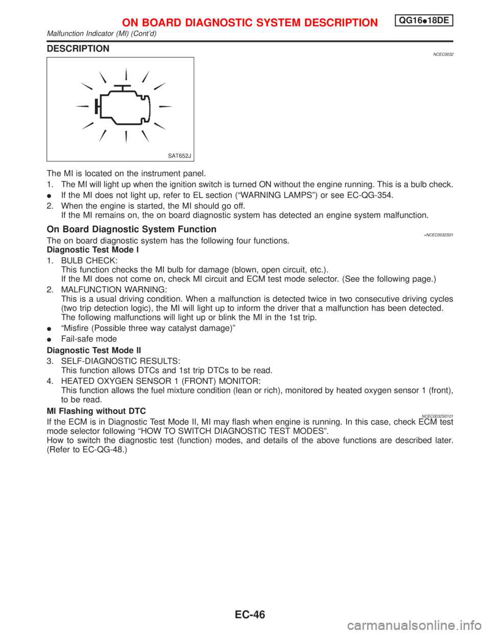
The MI is located on the instrument panel.
1. The MI will light up when the ignition switch is turned ON without the engine running. This is a bulb check.
IIf the MI does not light up, refer to EL section (ªWARNING LAMPSº) or see EC-QG-354.
2. When the engine is started, the MI should go off.
If the MI remains on, the on board diagnostic system has detected an engine system malfunction.
On Board Diagnostic System Function=NCEC0032S01The on board diagnostic system has the following four functions.
Diagnostic Test Mode I
1. BULB CHECK:
This function checks the MI bulb for damage (blown, open circuit, etc.).
If the MI does not come on, check MI circuit and ECM test mode selector. (See the following page.)
2. MALFUNCTION WARNING:
This is a usual driving condition. When a malfunction is detected twice in two consecutive driving cycles
(two trip detection logic), the MI will light up to inform the driver that a malfunction has been detected.
The following malfunctions will light up or blink the MI in the 1st trip.
IªMisfire (Possible three way catalyst damage)º
IFail-safe mode
Diagnostic Test Mode II
3. SELF-DIAGNOSTIC RESULTS:
This function allows DTCs and 1st trip DTCs to be read.
4. HEATED OXYGEN SENSOR 1 (FRONT) MONITOR:
This function allows the fuel mixture condition (lean or rich), monitored by heated oxygen sensor 1 (front),
to be read.
MI Flashing without DTC
NCEC0032S0101If the ECM is in Diagnostic Test Mode II, MI may flash when engine is running. In this case, check ECM test
mode selector following ªHOW TO SWITCH DIAGNOSTIC TEST MODESº.
How to switch the diagnostic test (function) modes, and details of the above functions are described later.
(Refer to EC-QG-48.)
SAT652J
ON BOARD DIAGNOSTIC SYSTEM DESCRIPTIONQG16I18DE
Malfunction Indicator (MI) (Cont'd)
EC-46
Page 504 of 2267
![NISSAN PRIMERA 1999 Electronic Repair Manual DATA MONITOR (SPEC) MODENLEC1365S07
Monitored item [Unit]ECM
input
signalsMain
signalsDescription Remarks
MAS A/F SE-B1 [V]qqIThe signal voltage of the mass air flow sen-
sor specification is displaye NISSAN PRIMERA 1999 Electronic Repair Manual DATA MONITOR (SPEC) MODENLEC1365S07
Monitored item [Unit]ECM
input
signalsMain
signalsDescription Remarks
MAS A/F SE-B1 [V]qqIThe signal voltage of the mass air flow sen-
sor specification is displaye](/manual-img/5/57377/w960_57377-503.png)
DATA MONITOR (SPEC) MODENLEC1365S07
Monitored item [Unit]ECM
input
signalsMain
signalsDescription Remarks
MAS A/F SE-B1 [V]qqIThe signal voltage of the mass air flow sen-
sor specification is displayed.IWhen the engine is running, specifi-
cation range is indicated.
B/FUEL SCHDL
[msec]IªBase fuel scheduleº indicates the fuel injec-
tion pulse width programmed into ECM,
prior to any learned on board correction.IWhen the engine is running, specifi-
cation range is indicated.
A/F ALPHA-B1 [%]qIIndicates the mean value of the air-fuel ratio
feedback correction factor per cycle.IWhen the engine is running, specifi-
cation range is indicated.
IThis data also includes the data for
the air-fuel ratio learning control.
NOTE:
Any monitored item that does not match the vehicle being diagnosed is deleted from the display automatically.
ACTIVE TEST MODENCEC0034S07
TEST ITEM CONDITION JUDGEMENT CHECK ITEM (REMEDY)
FUEL INJECTIONIEngine: Return to the original
trouble condition
IChange the amount of fuel injec-
tion using CONSULT-II.If trouble symptom disappears, see
CHECK ITEM.IHarness and connector
IFuel injectors
IHeated oxygen sensor 1 (front)
IACV-AAC/V
OPENINGIEngine: After warming up, idle
the engine.
IChange the IACV-AAC valve
opening steps using CONSULT-
II.Engine speed changes according
to the opening steps.IHarness and connector
IIACV-AAC valve
ENG COOLANT
TEMPIEngine: Return to the original
trouble condition
IChange the engine coolant tem-
perature indication using CON-
SULT-II.If trouble symptom disappears, see
CHECK ITEM.IHarness and connector
IEngine coolant temperature sen-
sor
IFuel injectors
IGNITION TIMINGIEngine: Return to the original
trouble condition
ITiming light: Set
IRetard the ignition timing using
CONSULT-II.If trouble symptom disappears, see
CHECK ITEM.IªBase Idle Air Volume Initializingº
(Refer to EC-QG-33.)
ICamshaft position sensor
(PHASE)
ICrankshaft position sensor
(POS)
IEngine component parts and
installing conditions
POWER BAL-
ANCEIEngine: After warming up, idle
the engine.
IAir conditioner switch ªOFFº
IShift lever ªNº
ICut off each injector signal one
at a time using CONSULT-II.Engine runs rough or dies.IHarness and connector
ICompression
IInjectors
IPower transistor
ISpark plugs
IIgnition coils
COOLING FANIIgnition switch: ON
ITurn the cooling fan ªONº and
ªOFFº using CONSULT-II.Cooling fan moves and stops.IHarness and connector
ICooling fan motor
FUEL PUMP
RELAYIIgnition switch: ON
(Engine stopped)
ITurn the fuel pump relay ªONº
and ªOFFº using CONSULT-II
and listen to operating sound.Fuel pump relay makes the operat-
ing sound.IHarness and connector
IFuel pump relay
ON BOARD DIAGNOSTIC SYSTEM DESCRIPTIONQG16I18DE
CONSULT-II (Cont'd)
EC-62
Page 514 of 2267
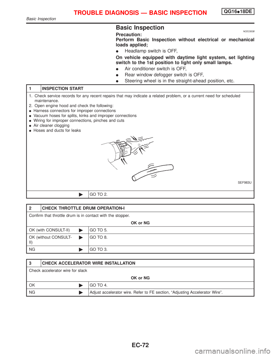
Basic InspectionNCEC0038Precaution:
Perform Basic Inspection without electrical or mechanical
loads applied;
IHeadlamp switch is OFF,
On vehicle equipped with daytime light system, set lighting
switch to the 1st position to light only small lamps.
IAir conditioner switch is OFF,
IRear window defogger switch is OFF,
ISteering wheel is in the straight-ahead position, etc.
1 INSPECTION START
1. Check service records for any recent repairs that may indicate a related problem, or a current need for scheduled
maintenance.
2. Open engine hood and check the following:
IHarness connectors for improper connections
IVacuum hoses for splits, kinks and improper connections
IWiring for improper connections, pinches and cuts
IAir cleaner clogging
IHoses and ducts for leaks
SEF983U
©GO TO 2.
2 CHECK THROTTLE DRUM OPERATION-I
Confirm that throttle drum is in contact with the stopper.
OK or NG
OK (with CONSULT-II)©GO TO 5.
OK (without CONSULT-
II)©GO TO 8.
NG©GO TO 3.
3 CHECK ACCELERATOR WIRE INSTALLATION
Check accelerator wire for slack
OK or NG
OK©GO TO 4.
NG©Adjust accelerator wire. Refer to FE section, ªAdjusting Accelerator Wireº.
TROUBLE DIAGNOSIS Ð BASIC INSPECTIONQG16I18DE
Basic Inspection
EC-72
Page 519 of 2267
18 CHECK TARGET IDLE SPEED AGAIN
With CONSULT-II
1. Start engine and warm it up to normal operating temperature.
2. Select ªENG SPEEDº in ªDATA MONITORº mode With CONSULT-II.
3. Check idle speed.
700 50 rpm
Without CONSULT-II
1. Start engine and warm it up to normal operating temperature.
2. Check idle speed.
700 50 rpm
OK or NG
OK©GO TO 20.
NG©GO TO 19.
19 CHECK ECM FUNCTION
1. Substitute another known-good ECM to check ECM function. (ECM may be the cause of a problem, but this is rarely
the case.)
2. Perform initialization of NATS system and registration of NATS ignition key IDs. Refer to ªNATS (Nissan Anti-Theft
System)º, EC-QG-45.
©GO TO 14.
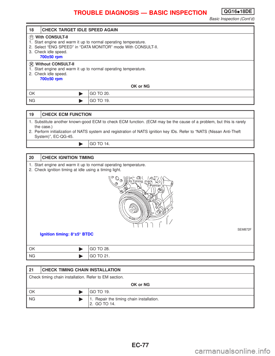
20 CHECK IGNITION TIMING
1. Start engine and warm it up to normal operating temperature.
2. Check ignition timing at idle using a timing light.
SEM872F
Ignition timing: 8É 5É BTDC
OK©GO TO 28.
NG©GO TO 21.
21 CHECK TIMING CHAIN INSTALLATION
Check timing chain installation. Refer to EM section.
OK or NG
OK©GO TO 19.
NG©1. Repair the timing chain installation.
2. GO TO 14.
TROUBLE DIAGNOSIS Ð BASIC INSPECTIONQG16I18DE
Basic Inspection (Cont'd)
EC-77
Page 520 of 2267
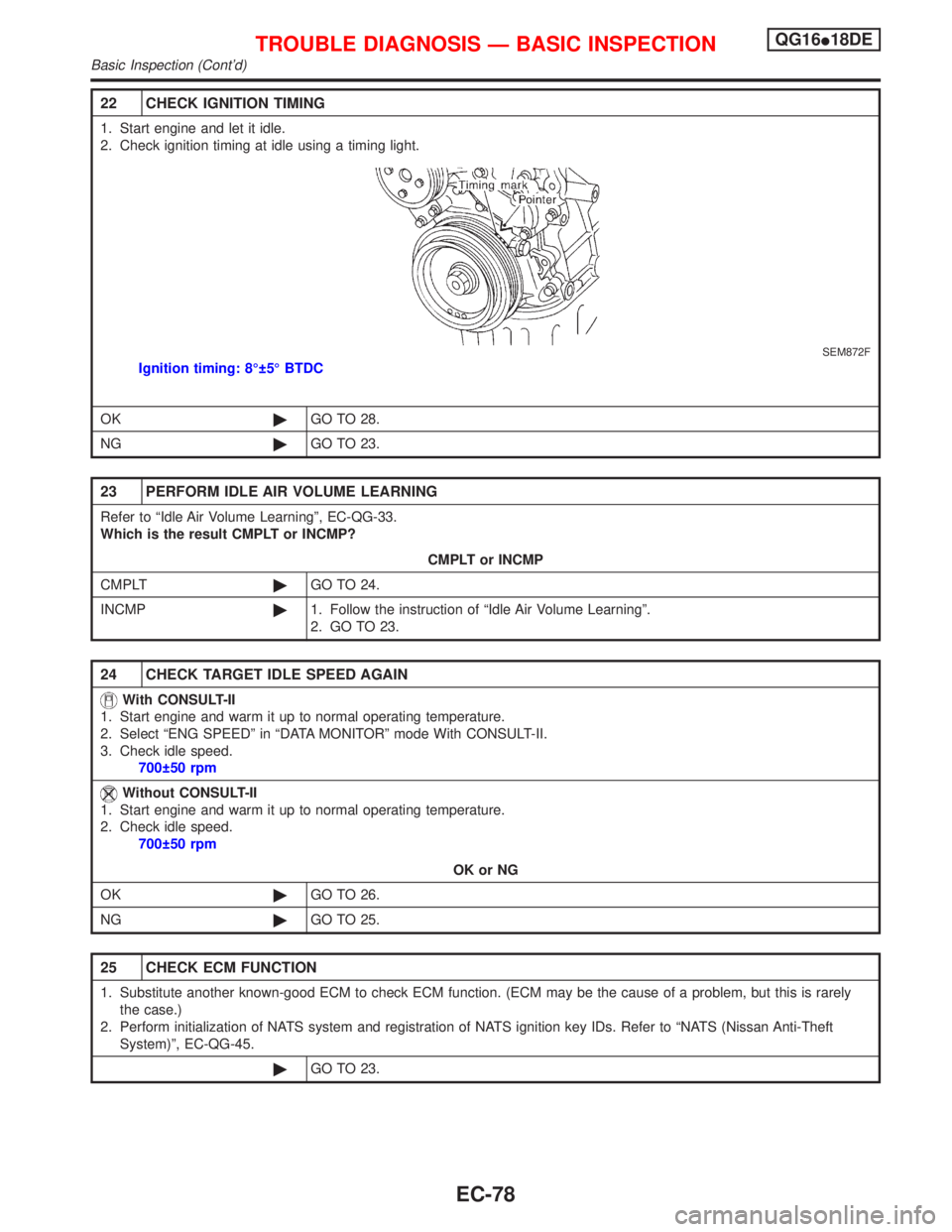
22 CHECK IGNITION TIMING
1. Start engine and let it idle.
2. Check ignition timing at idle using a timing light.
SEM872F
Ignition timing: 8É 5É BTDC
OK©GO TO 28.
NG©GO TO 23.
23 PERFORM IDLE AIR VOLUME LEARNING
Refer to ªIdle Air Volume Learningº, EC-QG-33.
Which is the result CMPLT or INCMP?
CMPLT or INCMP
CMPLT©GO TO 24.
INCMP©1. Follow the instruction of ªIdle Air Volume Learningº.
2. GO TO 23.
24 CHECK TARGET IDLE SPEED AGAIN
With CONSULT-II
1. Start engine and warm it up to normal operating temperature.
2. Select ªENG SPEEDº in ªDATA MONITORº mode With CONSULT-II.
3. Check idle speed.
700 50 rpm
Without CONSULT-II
1. Start engine and warm it up to normal operating temperature.
2. Check idle speed.
700 50 rpm
OK or NG
OK©GO TO 26.
NG©GO TO 25.
25 CHECK ECM FUNCTION
1. Substitute another known-good ECM to check ECM function. (ECM may be the cause of a problem, but this is rarely
the case.)
2. Perform initialization of NATS system and registration of NATS ignition key IDs. Refer to ªNATS (Nissan Anti-Theft
System)º, EC-QG-45.
©GO TO 23.
TROUBLE DIAGNOSIS Ð BASIC INSPECTIONQG16I18DE
Basic Inspection (Cont'd)
EC-78