Page 1846 of 2267

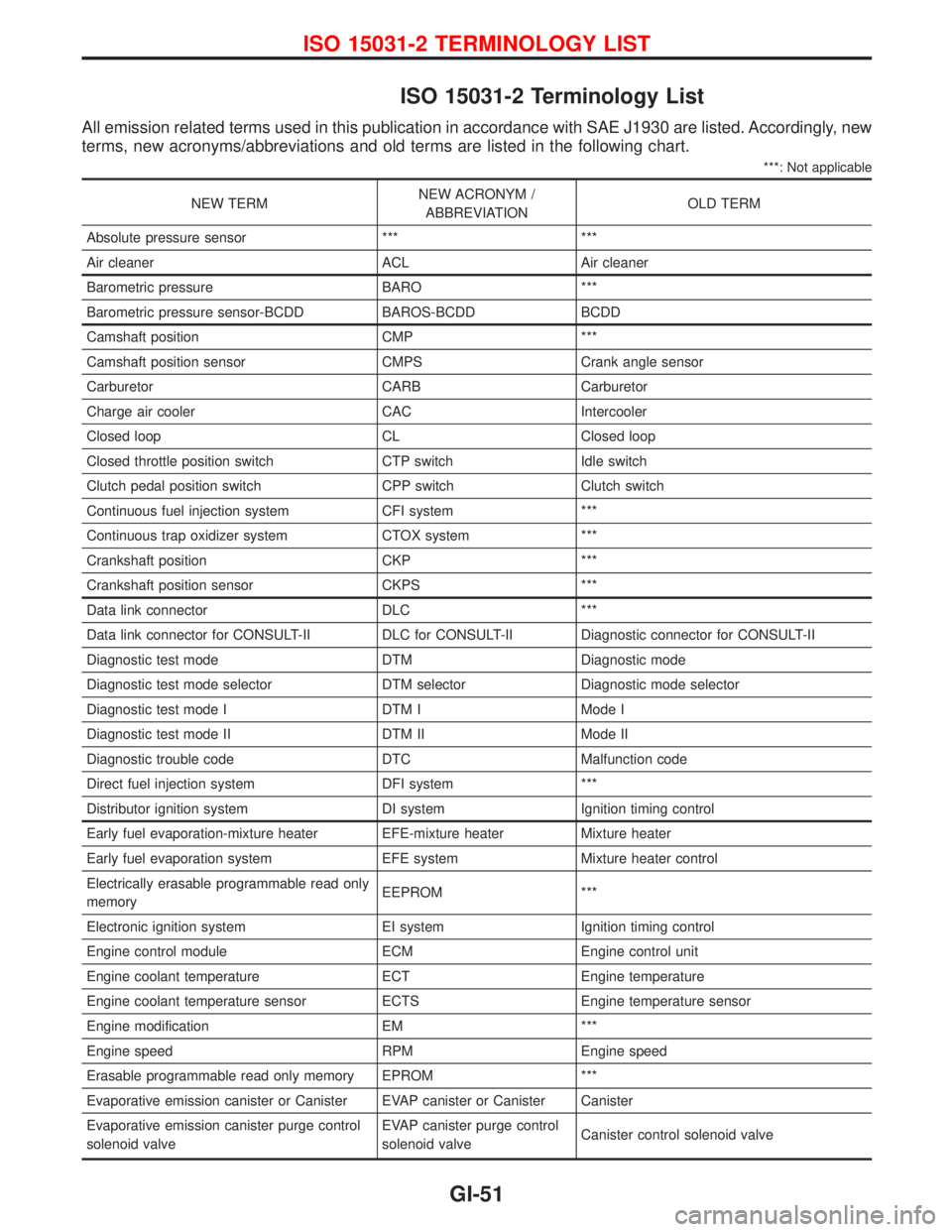
ISO 15031-2 Terminology List
All emission related terms used in this publication in accordance with SAE J1930 are listed. Accordingly, new
terms, new acronyms/abbreviations and old terms are listed in the following chart.
***: Not applicable
NEW TERMNEW ACRONYM /
ABBREVIATIONOLD TERM
Absolute pressure sensor *** ***
Air cleaner ACL Air cleaner
Barometric pressure BARO ***
Barometric pressure sensor-BCDD BAROS-BCDD BCDD
Camshaft position CMP ***
Camshaft position sensor CMPS Crank angle sensor
Carburetor CARB Carburetor
Charge air cooler CAC Intercooler
Closed loop CL Closed loop
Closed throttle position switch CTP switch Idle switch
Clutch pedal position switch CPP switch Clutch switch
Continuous fuel injection system CFI system ***
Continuous trap oxidizer system CTOX system ***
Crankshaft position CKP ***
Crankshaft position sensor CKPS ***
Data link connector DLC ***
Data link connector for CONSULT-II DLC for CONSULT-II Diagnostic connector for CONSULT-II
Diagnostic test mode DTM Diagnostic mode
Diagnostic test mode selector DTM selector Diagnostic mode selector
Diagnostic test mode I DTM I Mode I
Diagnostic test mode II DTM II Mode II
Diagnostic trouble code DTC Malfunction code
Direct fuel injection system DFI system ***
Distributor ignition system DI system Ignition timing control
Early fuel evaporation-mixture heater EFE-mixture heater Mixture heater
Early fuel evaporation system EFE system Mixture heater control
Electrically erasable programmable read only
memoryEEPROM ***
Electronic ignition system EI system Ignition timing control
Engine control module ECM Engine control unit
Engine coolant temperature ECT Engine temperature
Engine coolant temperature sensor ECTS Engine temperature sensor
Engine modification EM ***
Engine speed RPM Engine speed
Erasable programmable read only memory EPROM ***
Evaporative emission canister or Canister EVAP canister or Canister Canister
Evaporative emission canister purge control
solenoid valveEVAP canister purge control
solenoid valveCanister control solenoid valve
ISO 15031-2 TERMINOLOGY LIST
GI-51
Page 1850 of 2267

HEATER &
AIR CONDITIONER
SECTION
HA
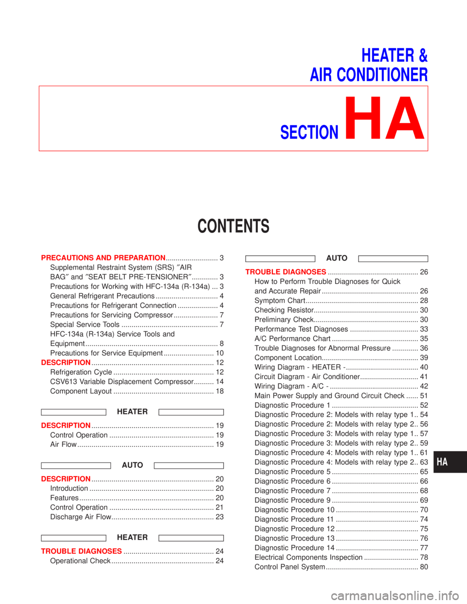
CONTENTS
PRECAUTIONS AND PREPARATION.......................... 3
Supplemental Restraint System (SRS)²AIR
BAG²and²SEAT BELT PRE-TENSIONER²............. 3
Precautions for Working with HFC-134a (R-134a) ... 3
General Refrigerant Precautions ............................... 4
Precautions for Refrigerant Connection .................... 4
Precautions for Servicing Compressor ...................... 7
Special Service Tools ................................................ 7
HFC-134a (R-134a) Service Tools and
Equipment .................................................................. 8
Precautions for Service Equipment ......................... 10
DESCRIPTION............................................................. 12
Refrigeration Cycle .................................................. 12
CSV613 Variable Displacement Compressor.......... 14
Component Layout .................................................. 18
HEATER
DESCRIPTION............................................................. 19
Control Operation .................................................... 19
Air Flow .................................................................... 19
AUTO
DESCRIPTION............................................................. 20
Introduction .............................................................. 20
Features ................................................................... 20
Control Operation .................................................... 21
Discharge Air Flow................................................... 23
HEATER
TROUBLE DIAGNOSES............................................. 24
Operational Check ................................................... 24
AUTO
TROUBLE DIAGNOSES............................................. 26
How to Perform Trouble Diagnoses for Quick
and Accurate Repair ................................................ 26
Symptom Chart ........................................................ 28
Checking Resistor.................................................... 30
Preliminary Check.................................................... 30
Performance Test Diagnoses .................................. 33
A/C Performance Chart ........................................... 35
Trouble Diagnoses for Abnormal Pressure ............. 36
Component Location................................................ 39
Wiring Diagram - HEATER -.................................... 40
Circuit Diagram - Air Conditioner............................. 41
Wiring Diagram - A/C - ............................................ 42
Main Power Supply and Ground Circuit Check ...... 51
Diagnostic Procedure 1 ........................................... 52
Diagnostic Procedure 2: Models with relay type 1.. 54
Diagnostic Procedure 2: Models with relay type 2.. 56
Diagnostic Procedure 3: Models with relay type 1.. 57
Diagnostic Procedure 3: Models with relay type 2.. 59
Diagnostic Procedure 4: Models with relay type 1.. 61
Diagnostic Procedure 4: Models with relay type 2.. 63
Diagnostic Procedure 5 ........................................... 65
Diagnostic Procedure 6 ........................................... 66
Diagnostic Procedure 7 ........................................... 68
Diagnostic Procedure 9 ........................................... 69
Diagnostic Procedure 10 ......................................... 70
Diagnostic Procedure 11 ......................................... 74
Diagnostic Procedure 12 ......................................... 75
Diagnostic Procedure 13 ......................................... 76
Diagnostic Procedure 14 ......................................... 77
Electrical Components Inspection ........................... 78
Control Panel System .............................................. 80
HA
Page 1867 of 2267
Component Layout
KHA104 Side defroster nozzle
Defroster nozzle
Side defroster nozzle
Side ventilator duct Center ventilator duct
Intake unit
Control assembly
(Heater) Cooler unit
Fresh vent
control leverHeater unitSide ventilator duct
For Scandinavian models only:
Rear heater duct
(Whenremoving rear heater
duct, it is necessary
to remove frontseats.)
SEC. 270×271×272×273
Control assembly
(Air conditioner)
DESCRIPTION
HA-18
Page 1868 of 2267

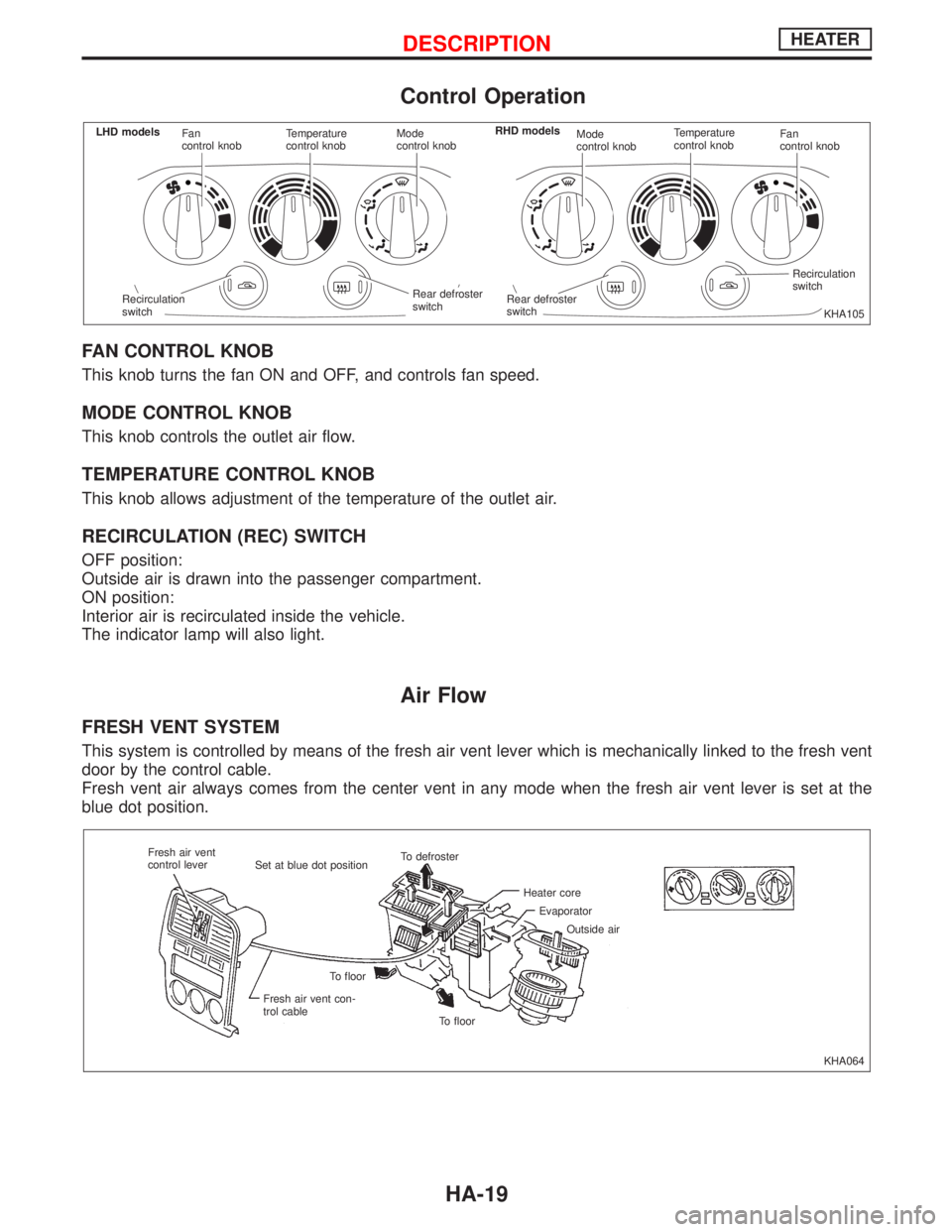
Control Operation
FAN CONTROL KNOB
This knob turns the fan ON and OFF, and controls fan speed.
MODE CONTROL KNOB
This knob controls the outlet air flow.
TEMPERATURE CONTROL KNOB
This knob allows adjustment of the temperature of the outlet air.
RECIRCULATION (REC) SWITCH
OFF position:
Outside air is drawn into the passenger compartment.
ON position:
Interior air is recirculated inside the vehicle.
The indicator lamp will also light.
Air Flow
FRESH VENT SYSTEM
This system is controlled by means of the fresh air vent lever which is mechanically linked to the fresh vent
door by the control cable.
Fresh vent air always comes from the center vent in any mode when the fresh air vent lever is set at the
blue dot position.
KHA105 Fan
control knobTemperature
control knobMode
control knobMode
control knobTemperature
control knobFan
control knob
Rear defroster
switchRecirculation
switch
.Rear defroster
switch Recirculation
switch LHD modelsRHD models
KHA064 Fresh air vent
control lever
Set at blue dot positionTo defroster
Heater core
Evaporator
Outside air
To floor To floor
Fresh air vent con-
trol cable
DESCRIPTIONHEATER
HA-19
Page 1872 of 2267
Discharge Air Flow
KHA113
p1: Ventilation
p2: Foot
p3: Defroster
H: Air flow in REC position
p3p3p3
p3
VentFoot
p3To defroster
p2To floor
p2To floor
Foot and defroster
p3To defroster
p2To floor
p2To floorOutside air
Defroster
p3To defroster
Outside air
p1To ventilator
Defroster door
Fresh vent door
Heater core
Intake airH
Intake door Air mix door Floor door
Ventilator door
Bi-level
p1To ventilator
p2To floor
p2To floor
This illustration is for LHD models.
The layout for RHD models issymmetrically opposite.Outside air
Air passed through heater core
Mixed air (
+)
Air not passed through heater core
p2
Outside air
DESCRIPTIONAUTO
HA-23
Page 1873 of 2267
Operational Check
The purpose of the operational check is to confirm that the sys-
tem operates as it should. The systems which are checked are
the blower, mode (discharge air), intake air, temperature
decrease, temperature increase.
CONDITIONS:
Engine running at normal operating temperature.
PROCEDURE:
1. Check blower
1) Turn fan control knob to 1-speed.
Blower should operate on 1-speed.
2) Then turn fan control knob to 2-speed.
3) Continue checking blower speed until all four speeds are
checked.
4) Leave blower on 4-speed.
2. Check discharge air
1) Turn mode control knob.
2) Confirm that discharge air comes out according to the air
distribution table at left.
Refer to ªDischarge Air Flowº in ªDESCRIPTIONº (HA-23).
KHA106
KHA107
KHA032 Discharge airflow
Switch
mode/
indicatorAiroutlet/distribution
Face Foot Defroster
100% Ð Ð
60% 40% Ð
15%* 65% 20%
15%* 55% 30%
15%* Ð 85%
* Face air from SIDE VENT only
TROUBLE DIAGNOSESHEATER
HA-24
Page 1874 of 2267
3. Check recirculation
1) Press recirculation switch.
Recirculation indicator should light.
2) Listen for intake door position change (you should hear
blower sound change slightly).
4. Check temperature decrease
1) Turn temperature control knob to full cold.
2) Check for cold air at discharge air outlets.
5. Check temperature increase
1) Turn temperature control knob to full hot.
2) Check for hot air at discharge air outlets.
KHA108
KHA109
KHA110
TROUBLE DIAGNOSESHEATER
Operational Check (Cont'd)
HA-25
Page 1889 of 2267
Wiring Diagram Ð HEATER Ð
YHA336
IGNITION SWITCH
ONIGNITION SWITCH
ON or START
FUSE BLOCK
(J/B)Refer to EL-POWER.
INTAKE DOOR
MOTOR
BLOWER
MOTOR
FAN RESISTOR
RECFRERECFRERECIRCULATION
SWITCH
FA N
SWITCH
OFF
REFER TO THE FOLLOWING
FUSE BLOCK - Junction Box (J/B) FRE
REC
TROUBLE DIAGNOSESAUTO
HA-40