1999 NISSAN PRIMERA heater
[x] Cancel search: heaterPage 873 of 2267
![NISSAN PRIMERA 1999 Electronic Repair Manual Monitored item [Unit]ECM
input
signalsMain
signalsDescription Remarks
AIR COND SIG
[ON/OFF]qqIIndicates [ON/OFF] condition of the air
conditioner switch as determined by the
air conditioning signal.
P NISSAN PRIMERA 1999 Electronic Repair Manual Monitored item [Unit]ECM
input
signalsMain
signalsDescription Remarks
AIR COND SIG
[ON/OFF]qqIIndicates [ON/OFF] condition of the air
conditioner switch as determined by the
air conditioning signal.
P](/manual-img/5/57377/w960_57377-872.png)
Monitored item [Unit]ECM
input
signalsMain
signalsDescription Remarks
AIR COND SIG
[ON/OFF]qqIIndicates [ON/OFF] condition of the air
conditioner switch as determined by the
air conditioning signal.
P/N POSI SW
[ON/OFF]qqIIndicates [ON/OFF] condition from the
PNP switch signal.
PW/ST SIGNAL
[ON/OFF]qqIIndicates [ON/OFF] condition of the
power steering oil pressure switch deter-
mined by the power steering oil pressure
switch signal.
LOAD SIGNAL
[ON/OFF]qqIIndicates [ON/OFF] condition from the
electrical load signal and/or lighting
switch.
ON ... rear defogger is operating and/or
lighting switch is on.
OFF ... rear defogger is not operating
and lighting switch is not on.
IGNITION SW
[ON/OFF]qIIndicates [ON/OFF] condition from igni-
tion switch.
HEATER FAN SW
[ON/OFF]qIIndicates [ON/OFF] condition from the
heater fan switch.
INJ PULSE -B1
[msec]qIIndicates the actual fuel injection pulse
width compensated by ECM according to
the input signals.IWhen the engine is stopped, a cer-
tain computed value is indicated.
B/FUEL SCHDL
[msec]IªBase fuel scheduleº indicates the fuel
injection pulse width programmed into
ECM, prior to any learned on board cor-
rection.
IGN TIMING [BTDC]qIIndicates the ignition timing computed by
ECM according to the input signals.
IACV-AAC/V [step]qIIndicates the IACV-AAC valve control
value computed by ECM according to
the input signals.
A/F ALPHA -B1 [%]qIIndicates the mean value of the air-fuel
ratio feedback correction factor per
cycle.IWhen the engine is stopped, a cer-
tain value is indicated.
IThis data also includes the data for
the air-fuel ratio learning control.
AIR COND RLY
[ON/OFF]qIIndicates the air conditioner relay control
condition determined by ECM according
to the input signals.
FUEL PUMP RLY
[ON/OFF]qIIndicates the fuel pump relay control
condition determined by ECM according
to the input signals.
COOLING FAN
[HI/LOW/OFF]qIIndicates the control condition of the
cooling fan determined by ECM accord-
ing to the input signals.
HI ... High speed operation
LOW ... Low speed operation
OFF ... Stop
HO2S1 HTR (B1)
[ON/OFF]IIndicates [ON/OFF] condition of heated
oxygen sensor 1 (front) heater deter-
mined by ECM according to the input
signals.
ON BOARD DIAGNOSTIC SYSTEM DESCRIPTIONSR20DE
CONSULT-II (Cont'd)
EC-73
Page 874 of 2267
![NISSAN PRIMERA 1999 Electronic Repair Manual Monitored item [Unit]ECM
input
signalsMain
signalsDescription Remarks
HO2S2 HTR (B1)
[ON/OFF]IIndicates [ON/OFF] condition of heated
oxygen sensor 2 (rear) heater deter-
mined by ECM according to the NISSAN PRIMERA 1999 Electronic Repair Manual Monitored item [Unit]ECM
input
signalsMain
signalsDescription Remarks
HO2S2 HTR (B1)
[ON/OFF]IIndicates [ON/OFF] condition of heated
oxygen sensor 2 (rear) heater deter-
mined by ECM according to the](/manual-img/5/57377/w960_57377-873.png)
Monitored item [Unit]ECM
input
signalsMain
signalsDescription Remarks
HO2S2 HTR (B1)
[ON/OFF]IIndicates [ON/OFF] condition of heated
oxygen sensor 2 (rear) heater deter-
mined by ECM according to the input
signals.
PURG VOL C/V [%]IIndicates the EVAP canister purge vol-
ume control solenoid valve computed by
the ECM according to the input signals.
IThe opening becomes larger as the
value increases.
CAL/LD VALUE [%]IªCalculated load valueº indicates the
value of the current airflow divided by
peak airflow.
ABSOL TH×P/S [%]IªAbsolute throttle position sensorº indi-
cates the throttle opening computed by
ECM according to the signal voltage of
the throttle position sensor.
MASS AIRFLOW
[gm/s]IIndicates the mass airflow computed by
ECM according to the signal voltage of
the mass air flow sensor.
IDL A/V LEANIDisplay the condition of idle air volume
learning
YET...Idle air volume learning has not
been performed yet.
CMPLT...Idle air volume learning has
already been performed successfully.
INCMP...Idle air volume learning has not
been performed successfully.
TRVL AFTER MIL
[km] or [Mile]IDistance traveled while MI is activated
VOLTAGE [V]IVoltage measured by the voltage probe.
PULSE
[msec] or [Hz] or [%]IPulse width, frequency or duty cycle
measured by the pulse probe.IOnly ª#º is displayed if item is unable
to be measured.
IFigures with ª#ºs are temporary ones.
They are the same figures as an
actual piece of data which was just
previously measured.
DATA MONITOR (SPEC) MODENLEC1365S07
Monitored item [Unit]ECM
input
signalsMain
signalsDescription Remarks
MAS A/F SE-B1 [V]qqIThe signal voltage of the mass air flow sen-
sor specification is displayed.IWhen the engine is running, specifi-
cation range is indicated.
B/FUEL SCHDL
[msec]IªBase fuel scheduleº indicates the fuel injec-
tion pulse width programmed into ECM,
prior to any learned on board correction.IWhen the engine is running, specifi-
cation range is indicated.
A/F ALPHA-B1 [%]qIIndicates the mean value of the air-fuel ratio
feedback correction factor per cycle.IWhen the engine is running, specifi-
cation range is indicated.
IThis data also includes the data for
the air-fuel ratio learning control.
NOTE:
Any monitored item that does not match the vehicle being diagnosed is deleted from the display automatically.
ON BOARD DIAGNOSTIC SYSTEM DESCRIPTIONSR20DE
CONSULT-II (Cont'd)
EC-74
Page 892 of 2267
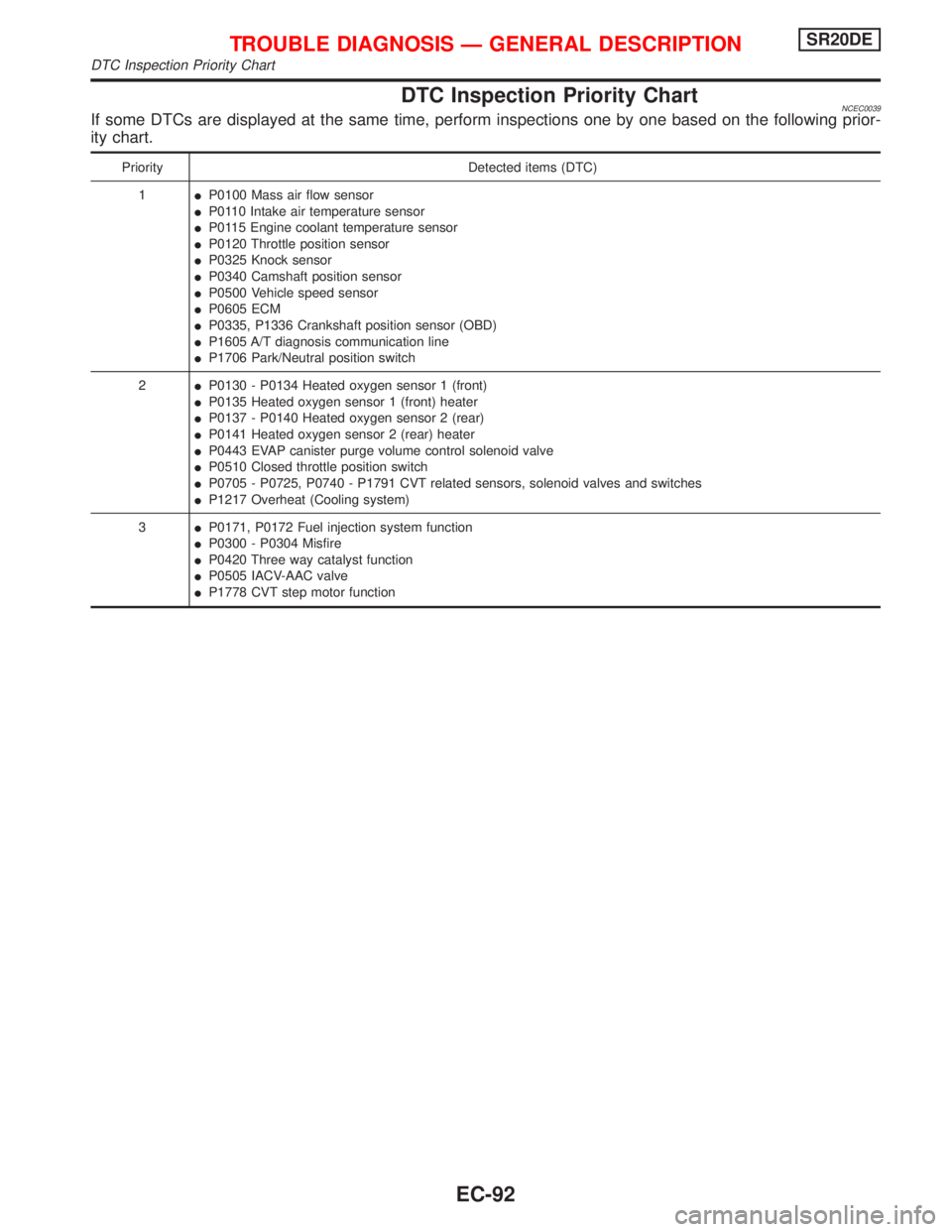
DTC Inspection Priority ChartNCEC0039If some DTCs are displayed at the same time, perform inspections one by one based on the following prior-
ity chart.
Priority Detected items (DTC)
1IP0100 Mass air flow sensor
IP0110 Intake air temperature sensor
IP0115 Engine coolant temperature sensor
IP0120 Throttle position sensor
IP0325 Knock sensor
IP0340 Camshaft position sensor
IP0500 Vehicle speed sensor
IP0605 ECM
IP0335, P1336 Crankshaft position sensor (OBD)
IP1605 A/T diagnosis communication line
IP1706 Park/Neutral position switch
2IP0130 - P0134 Heated oxygen sensor 1 (front)
IP0135 Heated oxygen sensor 1 (front) heater
IP0137 - P0140 Heated oxygen sensor 2 (rear)
IP0141 Heated oxygen sensor 2 (rear) heater
IP0443 EVAP canister purge volume control solenoid valve
IP0510 Closed throttle position switch
IP0705 - P0725, P0740 - P1791 CVT related sensors, solenoid valves and switches
IP1217 Overheat (Cooling system)
3IP0171, P0172 Fuel injection system function
IP0300 - P0304 Misfire
IP0420 Three way catalyst function
IP0505 IACV-AAC valve
IP1778 CVT step motor function
TROUBLE DIAGNOSIS Ð GENERAL DESCRIPTIONSR20DE
DTC Inspection Priority Chart
EC-92
Page 898 of 2267
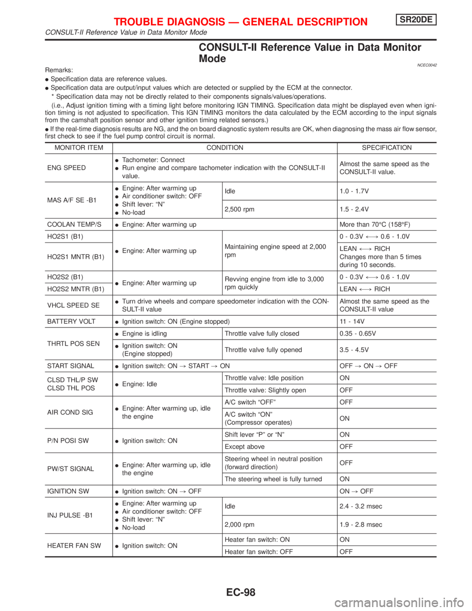
CONSULT-II Reference Value in Data Monitor
Mode
NCEC0042Remarks:
ISpecification data are reference values.
ISpecification data are output/input values which are detected or supplied by the ECM at the connector.
* Specification data may not be directly related to their components signals/values/operations.
(i.e., Adjust ignition timing with a timing light before monitoring IGN TIMING. Specification data might be displayed even when igni-
tion timing is not adjusted to specification. This IGN TIMING monitors the data calculated by the ECM according to the input signals
from the camshaft position sensor and other ignition timing related sensors.)
IIf the real-time diagnosis results are NG, and the on board diagnostic system results are OK, when diagnosing the mass air flow sensor,
first check to see if the fuel pump control circuit is normal.
MONITOR ITEM CONDITION SPECIFICATION
ENG SPEEDITachometer: Connect
IRun engine and compare tachometer indication with the CONSULT-II
value.Almost the same speed as the
CONSULT-II value.
MAS A/F SE -B1IEngine: After warming up
IAir conditioner switch: OFF
IShift lever: ªNº
INo-loadIdle 1.0 - 1.7V
2,500 rpm 1.5 - 2.4V
COOLAN TEMP/SIEngine: After warming up More than 70ÉC (158ÉF)
HO2S1 (B1)
IEngine: After warming upMaintaining engine speed at 2,000
rpm0 - 0.3V+,0.6 - 1.0V
HO2S1 MNTR (B1)LEAN+,RICH
Changes more than 5 times
during 10 seconds.
HO2S2 (B1)
IEngine: After warming upRevving engine from idle to 3,000
rpm quickly0 - 0.3V+,0.6 - 1.0V
HO2S2 MNTR (B1)LEAN+,RICH
VHCL SPEED SEITurn drive wheels and compare speedometer indication with the CON-
SULT-II valueAlmost the same speed as the
CONSULT-II value
BATTERY VOLTIIgnition switch: ON (Engine stopped) 11 - 14V
THRTL POS SENIEngine is idling Throttle valve fully closed 0.35 - 0.65V
IIgnition switch: ON
(Engine stopped)Throttle valve fully opened 3.5 - 4.5V
START SIGNALIIgnition switch: ON,START,ON OFF,ON,OFF
CLSD THL/P SW
CLSD THL POSIEngine: IdleThrottle valve: Idle position ON
Throttle valve: Slightly open OFF
AIR COND SIGIEngine: After warming up, idle
the engineA/C switch ªOFFº OFF
A/C switch ªONº
(Compressor operates)ON
P/N POSI SWIIgnition switch: ONShift lever ªPº or ªNº ON
Except above OFF
PW/ST SIGNALIEngine: After warming up, idle
the engineSteering wheel in neutral position
(forward direction)OFF
The steering wheel is fully turned ON
IGNITION SWIIgnition switch: ON,OFF ON,OFF
INJ PULSE -B1IEngine: After warming up
IAir conditioner switch: OFF
IShift lever: ªNº
INo-loadIdle 2.4 - 3.2 msec
2,000 rpm 1.9 - 2.8 msec
HEATER FAN SWIIgnition switch: ONHeater fan switch: ON ON
Heater fan switch: OFF OFF
TROUBLE DIAGNOSIS Ð GENERAL DESCRIPTIONSR20DE
CONSULT-II Reference Value in Data Monitor Mode
EC-98
Page 904 of 2267
![NISSAN PRIMERA 1999 Electronic Repair Manual TERMI-
NAL
NO.WIRE
COLORITEM CONDITION DATA (DC Voltage)
3 W/RHeated oxygen sensor
2 (rear) heater[Engine is running]
IBelow 3,600 rpm [After driving for 2 minutes
at a speed of 70 km/h (43 MPH) or mo NISSAN PRIMERA 1999 Electronic Repair Manual TERMI-
NAL
NO.WIRE
COLORITEM CONDITION DATA (DC Voltage)
3 W/RHeated oxygen sensor
2 (rear) heater[Engine is running]
IBelow 3,600 rpm [After driving for 2 minutes
at a speed of 70 km/h (43 MPH) or mo](/manual-img/5/57377/w960_57377-903.png)
TERMI-
NAL
NO.WIRE
COLORITEM CONDITION DATA (DC Voltage)
3 W/RHeated oxygen sensor
2 (rear) heater[Engine is running]
IBelow 3,600 rpm [After driving for 2 minutes
at a speed of 70 km/h (43 MPH) or more]Approximately 0.7V
[Ignition switch ªONº]
IEngine stopped
IEngine speed is above 3,600 rpmBATTERY VOLTAGE
(11 - 14V)
4LHeated oxygen sensor
1 (front) heater[Engine is running]
IIdle speedApproximately 0V
[Engine is running]
IMore than 20 seconds after exceeding 3,200
rpmBATTERY VOLTAGE
(11 - 14V)
6
7
15
16BR
Y/B
P
ORIACV-AAC valve[Engine is running]
IWarm-up condition
IIdle speed0 - 14V
10 R/W CVT signal No. 3[Engine is running]
IIdle speed0V
13 LG/R Cooling fan relay[Engine is running]
ICooling fan is not operatingBATTERY VOLTAGE
(11 - 14V)
[Engine is running]
ICooling fan is operatingApproximately 0V
14 P/BEVAP canister purge
volume control solenoid
valve (ON/OFF duty)[Engine is running]
IWarm-up condition
IIdle speedBATTERY VOLTAGE
(11 - 14V)
[Engine is running]
IWarm-up condition
I2,000 rpm5 - 12V
SEF975W
19 L/R CVT signal No. 5[Engine is running]
IIdle speedApproximately 7.5V
21 B/P Fuel pump relay[Ignition switch ªONº]
IFor 2 seconds after turning ignition switch
ªONº
[Engine is running]0-1V
[Ignition switch ªONº]
IMore than 1 second after turning ignition
switch ªONºBATTERY VOLTAGE
(11 - 14V)
22 OR/L Malfunction indicator[Ignition switch ªONº]0-1V
[Engine is running]
IIdle speedBATTERY VOLTAGE
(11 - 14V)
23 Ð Air conditioner switch[Engine is running]
IBoth A/C switch and blower switch are ªONºApproximately 0V
[Engine is running]
IA/C switch is ªOFFºBATTERY VOLTAGE
(11 - 14V)
TROUBLE DIAGNOSIS Ð GENERAL DESCRIPTIONSR20DE
ECM Terminals and Reference Value (Cont'd)
EC-104
Page 951 of 2267
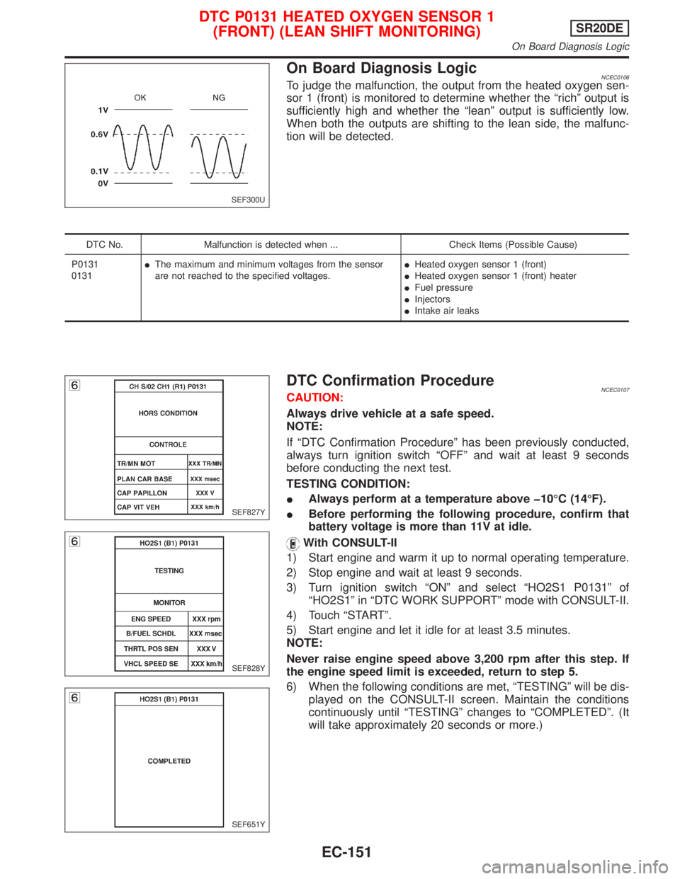
On Board Diagnosis LogicNCEC0106To judge the malfunction, the output from the heated oxygen sen-
sor 1 (front) is monitored to determine whether the ªrichº output is
sufficiently high and whether the ªleanº output is sufficiently low.
When both the outputs are shifting to the lean side, the malfunc-
tion will be detected.
DTC No. Malfunction is detected when ... Check Items (Possible Cause)
P0131
0131IThe maximum and minimum voltages from the sensor
are not reached to the specified voltages.IHeated oxygen sensor 1 (front)
IHeated oxygen sensor 1 (front) heater
IFuel pressure
IInjectors
IIntake air leaks
DTC Confirmation ProcedureNCEC0107CAUTION:
Always drive vehicle at a safe speed.
NOTE:
If ªDTC Confirmation Procedureº has been previously conducted,
always turn ignition switch ªOFFº and wait at least 9 seconds
before conducting the next test.
TESTING CONDITION:
IAlways perform at a temperature above þ10ÉC (14ÉF).
IBefore performing the following procedure, confirm that
battery voltage is more than 11V at idle.
With CONSULT-II
1) Start engine and warm it up to normal operating temperature.
2) Stop engine and wait at least 9 seconds.
3) Turn ignition switch ªONº and select ªHO2S1 P0131º of
ªHO2S1º in ªDTC WORK SUPPORTº mode with CONSULT-II.
4) Touch ªSTARTº.
5) Start engine and let it idle for at least 3.5 minutes.
NOTE:
Never raise engine speed above 3,200 rpm after this step. If
the engine speed limit is exceeded, return to step 5.
6) When the following conditions are met, ªTESTINGº will be dis-
played on the CONSULT-II screen. Maintain the conditions
continuously until ªTESTINGº changes to ªCOMPLETEDº. (It
will take approximately 20 seconds or more.)
SEF300U
SEF827Y
SEF828Y
SEF651Y
DTC P0131 HEATED OXYGEN SENSOR 1
(FRONT) (LEAN SHIFT MONITORING)SR20DE
On Board Diagnosis Logic
EC-151
Page 954 of 2267
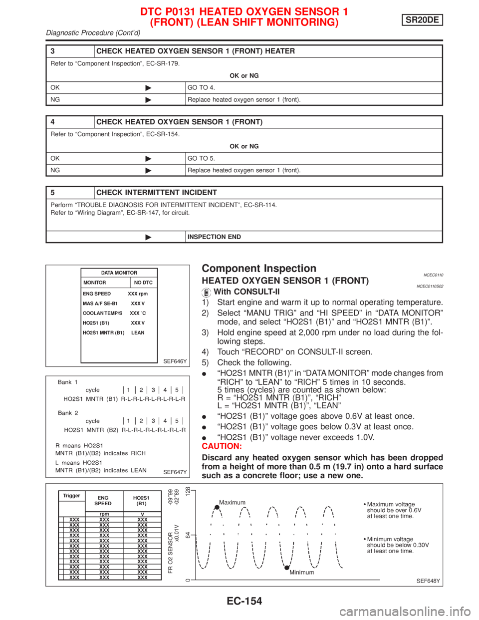
3 CHECK HEATED OXYGEN SENSOR 1 (FRONT) HEATER
Refer to ªComponent Inspectionº, EC-SR-179.
OK or NG
OK©GO TO 4.
NG©Replace heated oxygen sensor 1 (front).
4 CHECK HEATED OXYGEN SENSOR 1 (FRONT)
Refer to ªComponent Inspectionº, EC-SR-154.
OK or NG
OK©GO TO 5.
NG©Replace heated oxygen sensor 1 (front).
5 CHECK INTERMITTENT INCIDENT
Perform ªTROUBLE DIAGNOSIS FOR INTERMITTENT INCIDENTº, EC-SR-114.
Refer to ªWiring Diagramº, EC-SR-147, for circuit.
©INSPECTION END
Component InspectionNCEC0110HEATED OXYGEN SENSOR 1 (FRONT)NCEC0110S02With CONSULT-II
1) Start engine and warm it up to normal operating temperature.
2) Select ªMANU TRIGº and ªHI SPEEDº in ªDATA MONITORº
mode, and select ªHO2S1 (B1)º and ªHO2S1 MNTR (B1)º.
3) Hold engine speed at 2,000 rpm under no load during the fol-
lowing steps.
4) Touch ªRECORDº on CONSULT-II screen.
5) Check the following.
IªHO2S1 MNTR (B1)º in ªDATA MONITORº mode changes from
ªRICHº to ªLEANº to ªRICHº 5 times in 10 seconds.
5 times (cycles) are counted as shown below:
R = ªHO2S1 MNTR (B1)º, ªRICHº
L = ªHO2S1 MNTR (B1)º, ªLEANº
IªHO2S1 (B1)º voltage goes above 0.6V at least once.
IªHO2S1 (B1)º voltage goes below 0.3V at least once.
IªHO2S1 (B1)º voltage never exceeds 1.0V.
CAUTION:
Discard any heated oxygen sensor which has been dropped
from a height of more than 0.5 m (19.7 in) onto a hard surface
such as a concrete floor; use a new one.
SEF646Y
SEF647Y
SEF648Y
FR O2 SENSOR
x0.01V-09²99
-02²89
DTC P0131 HEATED OXYGEN SENSOR 1
(FRONT) (LEAN SHIFT MONITORING)SR20DE
Diagnostic Procedure (Cont'd)
EC-154
Page 957 of 2267
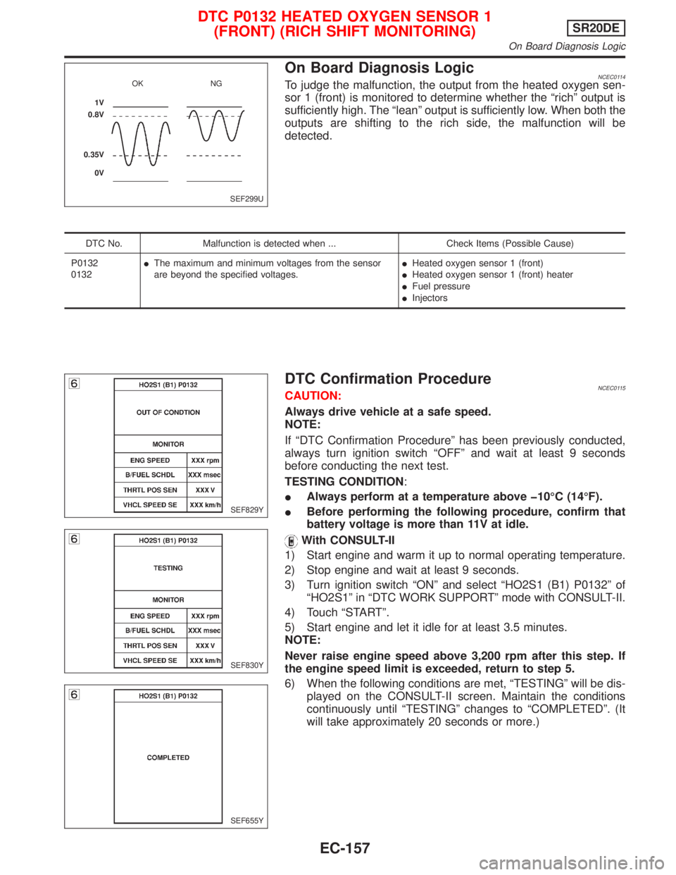
On Board Diagnosis LogicNCEC0114To judge the malfunction, the output from the heated oxygen sen-
sor 1 (front) is monitored to determine whether the ªrichº output is
sufficiently high. The ªleanº output is sufficiently low. When both the
outputs are shifting to the rich side, the malfunction will be
detected.
DTC No. Malfunction is detected when ... Check Items (Possible Cause)
P0132
0132IThe maximum and minimum voltages from the sensor
are beyond the specified voltages.IHeated oxygen sensor 1 (front)
IHeated oxygen sensor 1 (front) heater
IFuel pressure
IInjectors
DTC Confirmation ProcedureNCEC0115CAUTION:
Always drive vehicle at a safe speed.
NOTE:
If ªDTC Confirmation Procedureº has been previously conducted,
always turn ignition switch ªOFFº and wait at least 9 seconds
before conducting the next test.
TESTING CONDITION:
IAlways perform at a temperature above þ10ÉC (14ÉF).
IBefore performing the following procedure, confirm that
battery voltage is more than 11V at idle.
With CONSULT-II
1) Start engine and warm it up to normal operating temperature.
2) Stop engine and wait at least 9 seconds.
3) Turn ignition switch ªONº and select ªHO2S1 (B1) P0132º of
ªHO2S1º in ªDTC WORK SUPPORTº mode with CONSULT-II.
4) Touch ªSTARTº.
5) Start engine and let it idle for at least 3.5 minutes.
NOTE:
Never raise engine speed above 3,200 rpm after this step. If
the engine speed limit is exceeded, return to step 5.
6) When the following conditions are met, ªTESTINGº will be dis-
played on the CONSULT-II screen. Maintain the conditions
continuously until ªTESTINGº changes to ªCOMPLETEDº. (It
will take approximately 20 seconds or more.)
SEF299U OK NG
1V
0.8V
0.35V
0V
SEF829Y
SEF830Y
SEF655Y
DTC P0132 HEATED OXYGEN SENSOR 1
(FRONT) (RICH SHIFT MONITORING)SR20DE
On Board Diagnosis Logic
EC-157