1999 NISSAN PRIMERA heater
[x] Cancel search: heaterPage 499 of 2267
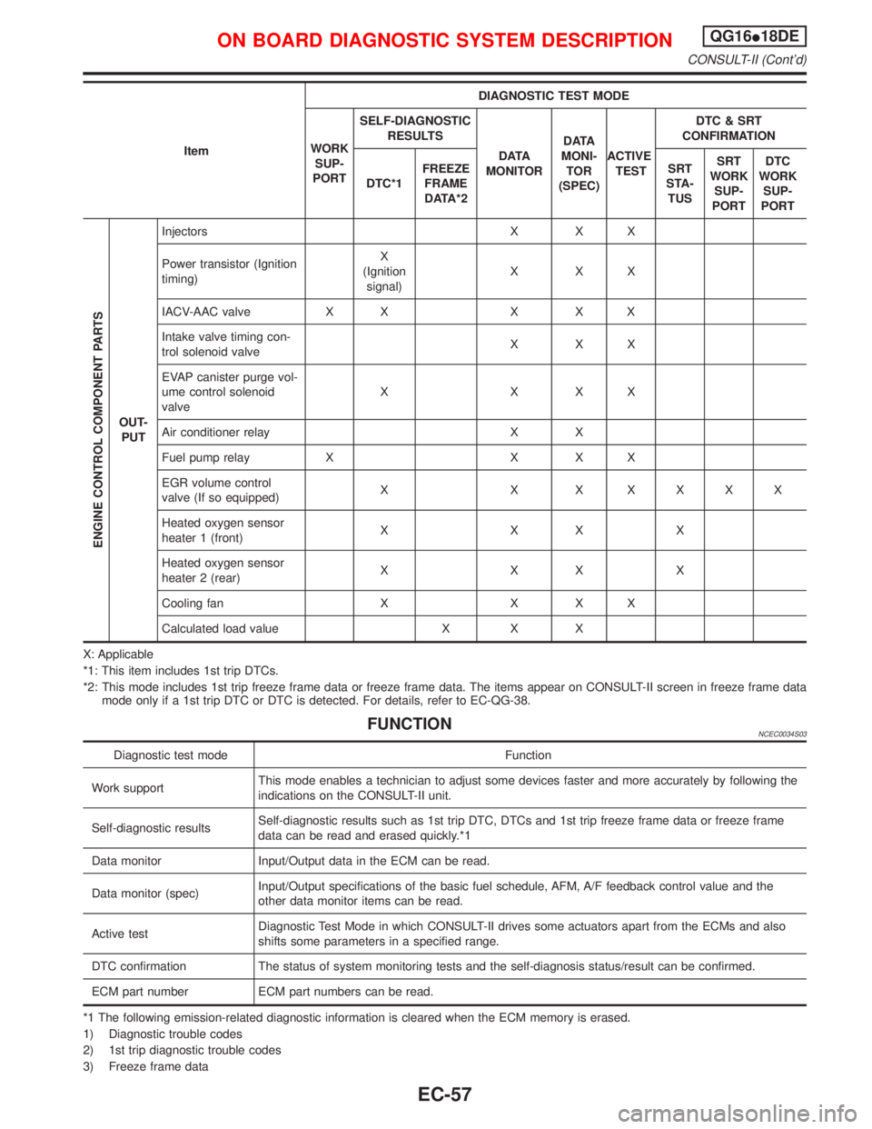
ItemDIAGNOSTIC TEST MODE
WORK
SUP-
PORTSELF-DIAGNOSTIC
RESULTS
D ATA
MONITORD ATA
MONI-
TOR
(SPEC)ACTIVE
TESTDTC & SRT
CONFIRMATION
DTC*1FREEZE
FRAME
DATA*2SRT
STA-
TUSSRT
WORK
SUP-
PORTDTC
WORK
SUP-
PORT
ENGINE CONTROL COMPONENT PARTS
OUT-
PUTInjectors X X X
Power transistor (Ignition
timing)X
(Ignition
signal)XXX
IACV-AAC valve X X X X X
Intake valve timing con-
trol solenoid valveXXX
EVAP canister purge vol-
ume control solenoid
valveXXXX
Air conditioner relay X X
Fuel pump relay X X X X
EGR volume control
valve (If so equipped)X X X XXXX
Heated oxygen sensor
heater 1 (front)XXXX
Heated oxygen sensor
heater 2 (rear)XXXX
Cooling fan X X X X
Calculated load value X X X
X: Applicable
*1: This item includes 1st trip DTCs.
*2: This mode includes 1st trip freeze frame data or freeze frame data. The items appear on CONSULT-II screen in freeze frame data
mode only if a 1st trip DTC or DTC is detected. For details, refer to EC-QG-38.
FUNCTIONNCEC0034S03
Diagnostic test mode Function
Work supportThis mode enables a technician to adjust some devices faster and more accurately by following the
indications on the CONSULT-II unit.
Self-diagnostic resultsSelf-diagnostic results such as 1st trip DTC, DTCs and 1st trip freeze frame data or freeze frame
data can be read and erased quickly.*1
Data monitor Input/Output data in the ECM can be read.
Data monitor (spec)Input/Output specifications of the basic fuel schedule, AFM, A/F feedback control value and the
other data monitor items can be read.
Active testDiagnostic Test Mode in which CONSULT-II drives some actuators apart from the ECMs and also
shifts some parameters in a specified range.
DTC confirmation The status of system monitoring tests and the self-diagnosis status/result can be confirmed.
ECM part number ECM part numbers can be read.
*1 The following emission-related diagnostic information is cleared when the ECM memory is erased.
1) Diagnostic trouble codes
2) 1st trip diagnostic trouble codes
3) Freeze frame data
ON BOARD DIAGNOSTIC SYSTEM DESCRIPTIONQG16I18DE
CONSULT-II (Cont'd)
EC-57
Page 502 of 2267
![NISSAN PRIMERA 1999 Electronic Repair Manual Monitored item [Unit]ECM
input
signalsMain
signalsDescription Remarks
AIR COND SIG
[ON/OFF]qqIIndicates [ON/OFF] condition of the air condi-
tioner switch as determined by the air condition-
ing signa NISSAN PRIMERA 1999 Electronic Repair Manual Monitored item [Unit]ECM
input
signalsMain
signalsDescription Remarks
AIR COND SIG
[ON/OFF]qqIIndicates [ON/OFF] condition of the air condi-
tioner switch as determined by the air condition-
ing signa](/manual-img/5/57377/w960_57377-501.png)
Monitored item [Unit]ECM
input
signalsMain
signalsDescription Remarks
AIR COND SIG
[ON/OFF]qqIIndicates [ON/OFF] condition of the air condi-
tioner switch as determined by the air condition-
ing signal.
P/N POSI SW
[ON/OFF]qqIIndicates [ON/OFF] condition from the PNP
switch signal.
PW/ST SIGNAL
[ON/OFF]qqIIndicates [ON/OFF] condition of the power steer-
ing oil pressure switch determined by the power
steering oil pressure switch signal.
LOAD SIGNAL
[ON/OFF]qqIIndicates [ON/OFF] condition from the electrical
load signal and/or lighting switch.
ON ... rear defogger is operating and/or lighting
switch is on.
OFF ... rear defogger is not operating and light-
ing switch is not on.
IGNITION SW
[ON/OFF]qIIndicates [ON/OFF] condition from ignition
switch.
HEATER FAN SW
[ON/OFF]qIIndicates [ON/OFF] condition from the heater
fan switch.
INJ PULSE-B1
[msec]qIIndicates the actual fuel injection pulse width
compensated by ECM according to the input
signals.IWhen the engine is stopped, a
certain computed value is indi-
cated.
B/FUEL SCHDL
[msec]IªBase fuel scheduleº indicates the fuel injection
pulse width programmed into ECM, prior to any
learned on board correction.
IGN TIMING [BTDC]qIIndicates the ignition timing computed by ECM
according to the input signals.
IACV-AAC/V [step]qIIndicates the IACV-AAC valve control value
computed by ECM according to the input sig-
nals.
A/F ALPHA-B1 [%]qIIndicates the mean value of the air-fuel ratio
feedback correction factor per cycle.IWhen the engine is stopped, a
certain value is indicated.
IThis data also includes the data
for the air-fuel ratio learning
control.
AIR COND RLY
[ON/OFF]qIIndicates the air conditioner relay control condi-
tion determined by ECM according to the input
signals.
FUEL PUMP RLY
[ON/OFF]qIIndicates the fuel pump relay control condition
determined by ECM according to the input sig-
nals.
INT/V SOL-B1
[ON/OFF]IThe control condition of the valve timing sole-
noid valve (determined by ECM according to the
input signal) is indicated.
ON ... Intake valve timing control operating
OFF ... Intake valve timing control not operating
COOLING FAN
[ON/OFF]qIIndicates the control condition of the cooling fan
determined by ECM according to the input sig-
nals.
HI ... High speed operation
LOW ... Low speed operation
OFF ... Stop
ON BOARD DIAGNOSTIC SYSTEM DESCRIPTIONQG16I18DE
CONSULT-II (Cont'd)
EC-60
Page 503 of 2267
![NISSAN PRIMERA 1999 Electronic Repair Manual Monitored item [Unit]ECM
input
signalsMain
signalsDescription Remarks
EGR VOL CON/V
[step]
(If so equipped)qIIndicates the EGR volume control valve com-
puted by the ECM according to the input sig-
na NISSAN PRIMERA 1999 Electronic Repair Manual Monitored item [Unit]ECM
input
signalsMain
signalsDescription Remarks
EGR VOL CON/V
[step]
(If so equipped)qIIndicates the EGR volume control valve com-
puted by the ECM according to the input sig-
na](/manual-img/5/57377/w960_57377-502.png)
Monitored item [Unit]ECM
input
signalsMain
signalsDescription Remarks
EGR VOL CON/V
[step]
(If so equipped)qIIndicates the EGR volume control valve com-
puted by the ECM according to the input sig-
nals.
IThe opening becomes larger as the value
increases.
HO2S1 HTR (B1)
[ON/OFF]IIndicates [ON/OFF] condition of heated oxygen
sensor 1 (front) heater determined by ECM
according to the input signals.
HO2S2 HTR (B1)
[ON/OFF]IIndicates [ON/OFF] condition of heated oxygen
sensor 2 (rear) heater determined by ECM
according to the input signals.
PURG VOL C/V [%]IIndicates the EVAP canister purge volume con-
trol solenoid valve computed by the ECM
according to the input signals.
IThe opening becomes larger as the value
increases.
CAL/LD VALUE [%]IªCalculated load valueº indicates the value of
the current air flow divided by peak air flow.
ABSOL TH.P/S [%]IªAbsolute throttle position sensorº indicates the
throttle opening computed by ECM according to
the signal voltage of the throttle position sensor.
MASS AIRFLOW
[gm/s]IIndicates the mass air flow computed by ECM
according to the signal voltage of the mass air
flow sensor.
TRVL AFTER MIL
[km] or [Mile]IDistance travelled while MI is activated
VOLTAGE [V]IVoltage measured by the voltage probe.
PULSE
[msec] or [Hz] or [%]IPulse width, frequency or duty cycle measured
by the pulse probe.IOnly ª#º is displayed if item is
unable to be measured.
IFigures with ª#ºs are temporary
ones. They are the same fig-
ures as an actual piece of data
which was just previously mea-
sured.
IDL A/V LEANIDisplay the condition of idle air volume learning
YET ... Idle air volume learning has not been
performed yet.
CMPLT ... Idle air volume learning has already
been performed successfully.
INCMP ... Idle air volume learning has not been
performed successfully.
NOTE:
Any monitored item that does not match the vehicle being diagnosed is deleted from the display automatically.
ON BOARD DIAGNOSTIC SYSTEM DESCRIPTIONQG16I18DE
CONSULT-II (Cont'd)
EC-61
Page 522 of 2267
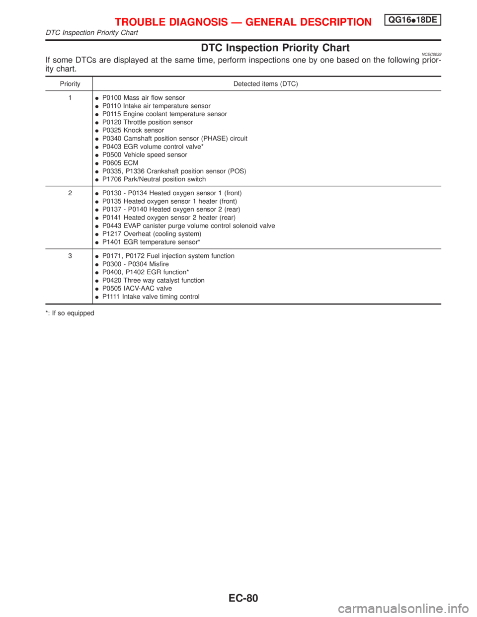
DTC Inspection Priority ChartNCEC0039If some DTCs are displayed at the same time, perform inspections one by one based on the following prior-
ity chart.
Priority Detected items (DTC)
1IP0100 Mass air flow sensor
IP0110 Intake air temperature sensor
IP0115 Engine coolant temperature sensor
IP0120 Throttle position sensor
IP0325 Knock sensor
IP0340 Camshaft position sensor (PHASE) circuit
IP0403 EGR volume control valve*
IP0500 Vehicle speed sensor
IP0605 ECM
IP0335, P1336 Crankshaft position sensor (POS)
IP1706 Park/Neutral position switch
2IP0130 - P0134 Heated oxygen sensor 1 (front)
IP0135 Heated oxygen sensor 1 heater (front)
IP0137 - P0140 Heated oxygen sensor 2 (rear)
IP0141 Heated oxygen sensor 2 heater (rear)
IP0443 EVAP canister purge volume control solenoid valve
IP1217 Overheat (cooling system)
IP1401 EGR temperature sensor*
3IP0171, P0172 Fuel injection system function
IP0300 - P0304 Misfire
IP0400, P1402 EGR function*
IP0420 Three way catalyst function
IP0505 IACV-AAC valve
IP 1111Intake valve timing control
*: If so equipped
TROUBLE DIAGNOSIS Ð GENERAL DESCRIPTIONQG16I18DE
DTC Inspection Priority Chart
EC-80
Page 530 of 2267
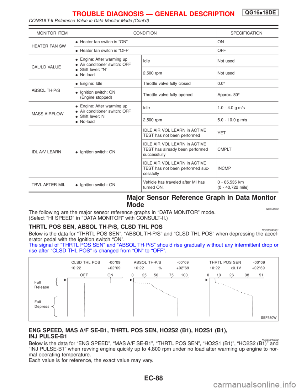
MONITOR ITEM CONDITION SPECIFICATION
HEATER FAN SWIHeater fan switch is ªONº ON
IHeater fan switch is ªOFF' OFF
CAL/LD VALUEIEngine: After warming up
IAir conditioner switch: OFF
IShift lever: ªNº
INo-loadIdle Not used
2,500 rpm Not used
ABSOL TH×P/SIEngine: Idle Throttle valve fully closed 0.0É
IIgnition switch: ON
(Engine stopped)Throttle valve fully opened Approx. 80É
MASS AIRFLOWIEngine: After warming up
IAir conditioner switch: OFF
IShift lever: N
INo-loadIdle 1.0 - 4.0 g×m/s
2,500 rpm 5.0 - 10.0 g×m/s
IDL A/V LEARNIIgnition switch: ONIDLE AIR VOL LEARN in ACTIVE
TEST has not been performedYET
IDLE AIR VOL LEARN in ACTIVE
TEST has already been performed
successfullyCMPLT
IDLE AIR VOL LEARN in ACTIVE
TEST has not been performed suc-
cessfullyINCMP
TRVL AFTER MILIIgnition switch: ONVehicle has traveled after MI has
turned ON.0 - 65,535 km
(0 - 40,722 mile)
Major Sensor Reference Graph in Data Monitor
Mode
NCEC0043The following are the major sensor reference graphs in ªDATA MONITORº mode.
(Select ªHI SPEEDº in ªDATA MONITORº with CONSULT-II.)
THRTL POS SEN, ABSOL TH×P/S, CLSD THL POSNCEC0043S01Below is the data for ªTHRTL POS SENº, ªABSOL TH×P/Sº and ªCLSD THL POSº when depressing the accel-
erator pedal with the ignition switch ªONº.
The signal of ªTHRTL POS SENº and ªABSOL TH×P/Sº should rise gradually without any intermittent drop or
rise after ªCLSD THL POSº is changed from ªONº to ªOFFº.
ENG SPEED, MAS A/F SE-B1, THRTL POS SEN, HO2S2 (B1), HO2S1 (B1),
INJ PULSE-B1
NCEC0043S02Below is the data for ªENG SPEEDº, ªMAS A/F SE-B1º, ªTHRTL POS SENº, ªHO2S1 (B1)º, ªHO2S2 (B1)º and
ªINJ PULSE-B1º when revving engine quickly up to 4,800 rpm under no load after warming up engine to nor-
mal operating temperature.
Each value is for reference, the exact value may vary.
Full
Release
Full
DepressCLSD THL POS -00"09 ABSOL TH P/S -00"09 THRTL POS SEN -00"09
10:22 +02"69 10:22 % +02"69 10:22 x0.1V +02"69
OFF ON 0 25 50 75 100 0 13 26 38 51
SEF580W
TROUBLE DIAGNOSIS Ð GENERAL DESCRIPTIONQG16I18DE
CONSULT-II Reference Value in Data Monitor Mode (Cont'd)
EC-88
Page 534 of 2267
![NISSAN PRIMERA 1999 Electronic Repair Manual TER-
MINAL
NO.WIRE
COLORITEM CONDITION DATA (DC Voltage)
1 Y/RIntake valve timing con-
trol solenoid valve[Engine is running]
IIdle speedBATTERY VOLTAGE
(11 - 14V)
[Engine is running]
ILift up drive w NISSAN PRIMERA 1999 Electronic Repair Manual TER-
MINAL
NO.WIRE
COLORITEM CONDITION DATA (DC Voltage)
1 Y/RIntake valve timing con-
trol solenoid valve[Engine is running]
IIdle speedBATTERY VOLTAGE
(11 - 14V)
[Engine is running]
ILift up drive w](/manual-img/5/57377/w960_57377-533.png)
TER-
MINAL
NO.WIRE
COLORITEM CONDITION DATA (DC Voltage)
1 Y/RIntake valve timing con-
trol solenoid valve[Engine is running]
IIdle speedBATTERY VOLTAGE
(11 - 14V)
[Engine is running]
ILift up drive wheels and shift gear ªONº
IRev engine up from 1,200 to 3,000 rpmApproximately 0V
3 W/RHeated oxygen sensor
2 heater (rear)[Engine is running]
IEngine speed is below 3,600 rpm
IAfter driving for 2 minutes at a speed of 70
km/h (43 MPH) or moreApproximately 0.7V
[Ignition switch ªONº]
IEngine stopped
IEngine speed is above 3,600 rpmBATTERY VOLTAGE
(11 - 14V)
4LHeated oxygen sensor
1 heater (front)[Engine is running]
IEngine speed is below 3,200 rpmApproximately 0V
[Engine is running]
IEngine speed is above 3,200 rpmBATTERY VOLTAGE
(11 - 14V)
6
7
15
16BR
Y/B
P
ORIACV-AAC valve[Engine is running]
IWarm-up condition
IIdle speed0.1 - 14V
8*
9*
17*
18*W/B
SB
G/R
R/YEGR volume control
valve[Engine is running]
IWarm-up condition
IRev engine up from 2,000 to 4,000 rpm0 - 14V
13 LG/R Cooling fan relay[Engine is running]
ICooling fan is not operatingBATTERY VOLTAGE
(11 - 14V)
[Engine is running]
ICooling fan is operatingApproximately 0V
14 P/BEVAP canister purge
volume control valve
(ON/OFF duty)[Engine is running]
IWarm-up condition
IAccelerator pedal depressed5 - 12V
SEF975W
21 B/P Fuel pump relay[Ignition switch ªONº]
IFor 1 second after turning ignition switch ªONº
[Engine is running]0-1V
[Ignition switch ªONº]
IMore than 1 second after turning ignition switch
ªONºBATTERY VOLTAGE
(11 - 14V)
22 OR/L Malfunction indicator[Ignition switch ªONº]0-1V
[Engine is running]
IIdle speedBATTERY VOLTAGE
(11 - 14V)
23 L/W Air conditioner relay[Engine is running]
IBoth A/C switch and blower switch are ªONºApproximately 0V
[Engine is running]
IA/C switch is ªOFFºBATTERY VOLTAGE
(11 - 14V)
*: If so equipped
TROUBLE DIAGNOSIS Ð GENERAL DESCRIPTIONQG16I18DE
ECM Terminals and Reference Value (Cont'd)
EC-92
Page 582 of 2267
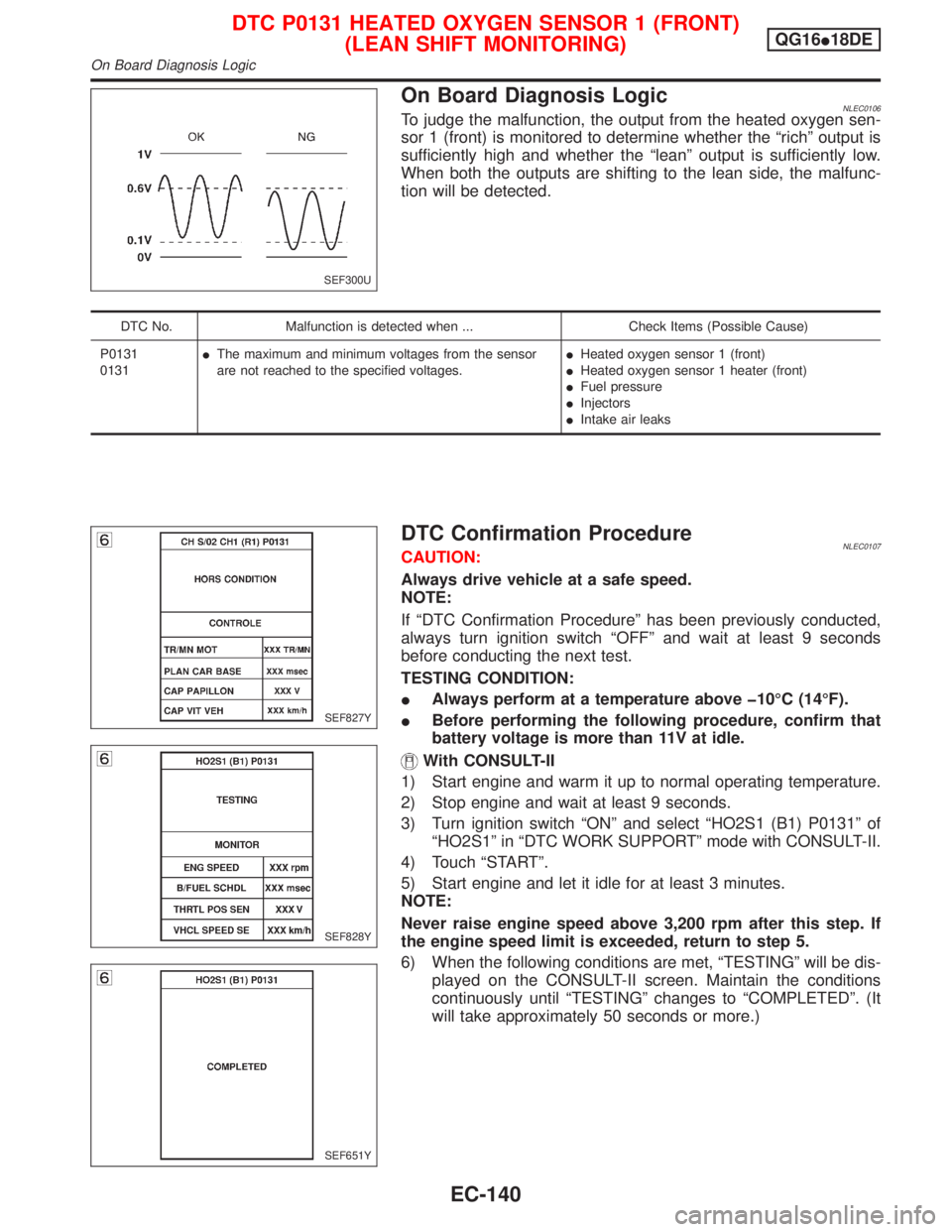
On Board Diagnosis LogicNLEC0106To judge the malfunction, the output from the heated oxygen sen-
sor 1 (front) is monitored to determine whether the ªrichº output is
sufficiently high and whether the ªleanº output is sufficiently low.
When both the outputs are shifting to the lean side, the malfunc-
tion will be detected.
DTC No. Malfunction is detected when ... Check Items (Possible Cause)
P0131
0131IThe maximum and minimum voltages from the sensor
are not reached to the specified voltages.IHeated oxygen sensor 1 (front)
IHeated oxygen sensor 1 heater (front)
IFuel pressure
IInjectors
IIntake air leaks
DTC Confirmation ProcedureNLEC0107CAUTION:
Always drive vehicle at a safe speed.
NOTE:
If ªDTC Confirmation Procedureº has been previously conducted,
always turn ignition switch ªOFFº and wait at least 9 seconds
before conducting the next test.
TESTING CONDITION:
IAlways perform at a temperature above þ10ÉC (14ÉF).
IBefore performing the following procedure, confirm that
battery voltage is more than 11V at idle.
With CONSULT-II
1) Start engine and warm it up to normal operating temperature.
2) Stop engine and wait at least 9 seconds.
3) Turn ignition switch ªONº and select ªHO2S1 (B1) P0131º of
ªHO2S1º in ªDTC WORK SUPPORTº mode with CONSULT-II.
4) Touch ªSTARTº.
5) Start engine and let it idle for at least 3 minutes.
NOTE:
Never raise engine speed above 3,200 rpm after this step. If
the engine speed limit is exceeded, return to step 5.
6) When the following conditions are met, ªTESTINGº will be dis-
played on the CONSULT-II screen. Maintain the conditions
continuously until ªTESTINGº changes to ªCOMPLETEDº. (It
will take approximately 50 seconds or more.)
SEF300U
SEF827Y
SEF828Y
SEF651Y
DTC P0131 HEATED OXYGEN SENSOR 1 (FRONT)
(LEAN SHIFT MONITORING)QG16I18DE
On Board Diagnosis Logic
EC-140
Page 584 of 2267
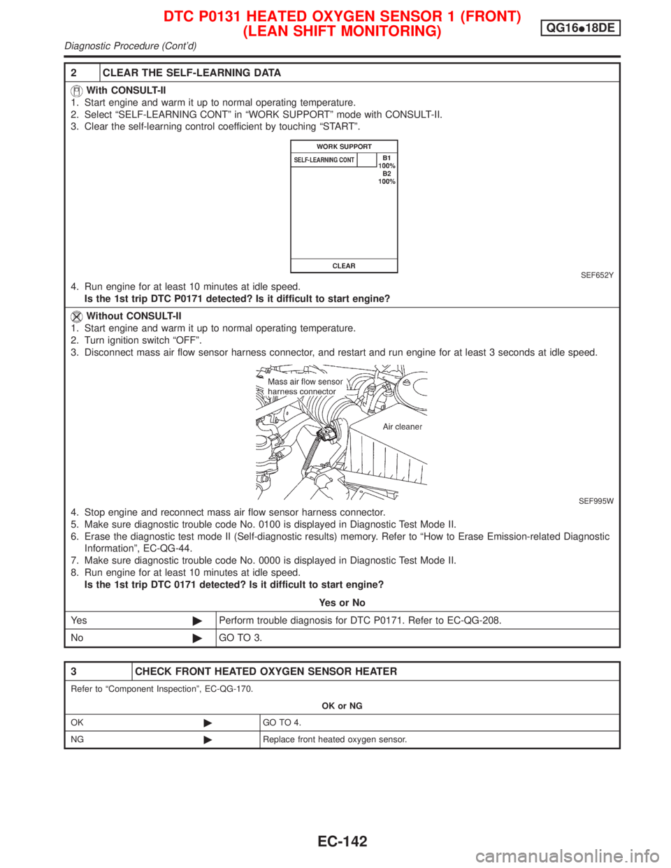
2 CLEAR THE SELF-LEARNING DATA
With CONSULT-II
1. Start engine and warm it up to normal operating temperature.
2. Select ªSELF-LEARNING CONTº in ªWORK SUPPORTº mode with CONSULT-II.
3. Clear the self-learning control coefficient by touching ªSTARTº.
SEF652Y
4. Run engine for at least 10 minutes at idle speed.
Is the 1st trip DTC P0171 detected? Is it difficult to start engine?
Without CONSULT-II
1. Start engine and warm it up to normal operating temperature.
2. Turn ignition switch ªOFFº.
3. Disconnect mass air flow sensor harness connector, and restart and run engine for at least 3 seconds at idle speed.
SEF995W
4. Stop engine and reconnect mass air flow sensor harness connector.
5. Make sure diagnostic trouble code No. 0100 is displayed in Diagnostic Test Mode II.
6. Erase the diagnostic test mode II (Self-diagnostic results) memory. Refer to ªHow to Erase Emission-related Diagnostic
Informationº, EC-QG-44.
7. Make sure diagnostic trouble code No. 0000 is displayed in Diagnostic Test Mode II.
8. Run engine for at least 10 minutes at idle speed.
Is the 1st trip DTC 0171 detected? Is it difficult to start engine?
YesorNo
Ye s©Perform trouble diagnosis for DTC P0171. Refer to EC-QG-208.
No©GO TO 3.
3 CHECK FRONT HEATED OXYGEN SENSOR HEATER
Refer to ªComponent Inspectionº, EC-QG-170.
OK or NG
OK©GO TO 4.
NG©Replace front heated oxygen sensor.
DTC P0131 HEATED OXYGEN SENSOR 1 (FRONT)
(LEAN SHIFT MONITORING)QG16I18DE
Diagnostic Procedure (Cont'd)
EC-142