1999 NISSAN PRIMERA air condition
[x] Cancel search: air conditionPage 470 of 2267
Positive Crankcase Ventilation
DESCRIPTIONNCEC0022
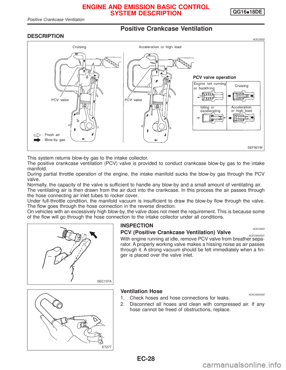
This system returns blow-by gas to the intake collector.
The positive crankcase ventilation (PCV) valve is provided to conduct crankcase blow-by gas to the intake
manifold.
During partial throttle operation of the engine, the intake manifold sucks the blow-by gas through the PCV
valve.
Normally, the capacity of the valve is sufficient to handle any blow-by and a small amount of ventilating air.
The ventilating air is then drawn from the air duct into the crankcase. In this process the air passes through
the hose connecting air inlet tubes to rocker cover.
Under full-throttle condition, the manifold vacuum is insufficient to draw the blow-by flow through the valve.
The flow goes through the hose connection in the reverse direction.
On vehicles with an excessively high blow-by, the valve does not meet the requirement. This is because some
of the flow will go through the hose connection to the intake collector under all conditions.
INSPECTIONNCEC0023PCV (Positive Crankcase Ventilation) ValveNCEC0023S01With engine running at idle, remove PCV valve from breather sepa-
rator. A properly working valve makes a hissing noise as air passes
through it. A strong vacuum should be felt immediately when a fin-
ger is placed over the valve inlet.
Ventilation HoseNCEC0023S021. Check hoses and hose connections for leaks.
2. Disconnect all hoses and clean with compressed air. If any
hose cannot be freed of obstructions, replace.
SEF921W
SEC137A
ET277
ENGINE AND EMISSION BASIC CONTROL
SYSTEM DESCRIPTIONQG16I18DE
Positive Crankcase Ventilation
EC-28
Page 475 of 2267
Idle Air Volume LearningNCEC0541DESCRIPTIONNCEC0541S01ªIdle Air Volume Learningº is an operation to learn the idle air vol-
ume that keeps each engine within the specific range. It must be
performed under any of the following conditions:
IEach time IACV-AAC valve, throttle body or ECM is replaced.
IIdle speed or ignition timing is out of specification.
PRE-CONDITIONINGNCEC0541S04Before performing ªIdle Air Volume Learningº, make sure that all of
the following conditions are satisfied.
Learning will be cancelled if any of the following conditions are
missed for even a moment.
IBattery voltage: More than 12.9V (At idle)
IEngine coolant temperature: 70 - 99ÉC (158 - 210ÉF)
IPNP switch: ON
IElectric load switch: OFF
(Air conditioner, headlamp, rear window defogger)
On vehicles equipped with daytime light systems, set lighting
switch to the 1st position to light only small lamps.
ICooling fan motor: Not operating
ISteering wheel: Neutral (Straight-ahead position)
IVehicle speed: Stopped
ITransmission: warmed-up (Drive vehicle for 10 minutes.)
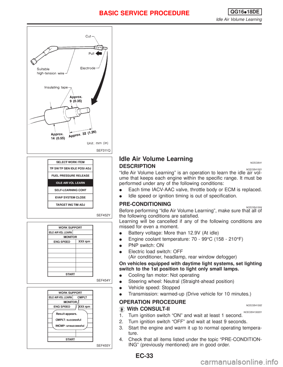
OPERATION PROCEDURENCEC0541S02With CONSULT-IINCEC0541S02011. Turn ignition switch ªONº and wait at least 1 second.
2. Turn ignition switch ªOFFº and wait at least 9 seconds.
3. Start the engine and warm it up to normal operating tempera-
ture.
4. Check that all items listed under the topic ªPRE-CONDITION-
INGº (previously mentioned) are in good order.
SEF311Q
SEF452Y
SEF454Y
SEF455Y
BASIC SERVICE PROCEDUREQG16I18DE
Idle Air Volume Learning
EC-33
Page 476 of 2267
5. Turn ignition switch ªOFFº and wait at least 9 seconds.
6. Start the engine and let it to idle for at least 28 seconds.
7. Select ªIDLE AIR VOL LEARNº in ªWORK SUPPORTº mode.
8. Touch ªSTARTº and wait 20 seconds.
9. Make sure that ªCMPLTº is displayed on CONSULT-II screen.
If ªINCMPº is displayed, ªIdle Air Volume Learningº will not be
carried out successfully. In this case, find the cause of the
problem by referring to the NOTE below.
10. Rev up the engine two or three times. Make sure that idle
speed and ignition timing are close to or within specifications.
ITEM SPECIFICATION
Idle speed 700 50 rpm
Ignition timing 8É 5É BTDC
Without CONSULT-IINCEC0541S02021. Turn ignition switch ªONº and wait at least 1 second.
2. Turn ignition switch ªOFFº and wait at least 9 seconds.
3. Start the engine and warm it up to normal operating tempera-
ture.
4. Check that all items listed under the topic ªPRE-CONDITION-
INGº (previously mentioned) are in good order.
5. Turn ignition switch ªOFFº and wait at least 9 seconds.
6. Start the engine and let it to idle for at least 28 seconds.
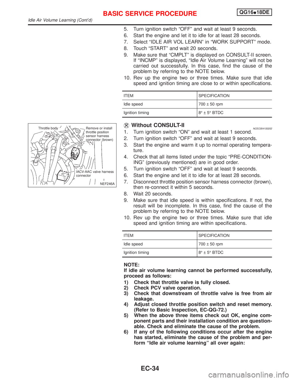
7. Disconnect throttle position sensor harness connector (brown),
then re-connect it within 5 seconds.
8. Wait 20 seconds.
9. Make sure that idle speed is within specifications. If not, the
result will be incomplete. In this case, find the cause of the
problem by referring to the NOTE below.
10. Rev up the engine two or three times. Make sure that idle
speed and ignition timing are within specifications.
ITEM SPECIFICATION
Idle speed 700 50 rpm
Ignition timing 8É 5É BTDC
NOTE:
If idle air volume learning cannot be performed successfully,
proceed as follows:
1) Check that throttle valve is fully closed.
2) Check PCV valve operation.
3) Check that downstream of throttle valve is free from air
leakage.
4) Adjust closed throttle position switch and reset memory.
(Refer to Basic Inspection, EC-QG-72.)
5) When the above three items check out OK, engine com-
ponent parts and their installation condition are question-
able. Check and eliminate the cause of the problem.
6) If any of the following conditions occur after the engine
has started, eliminate the cause of the problem and per-
form ªIdle air volume learningº all over again:
NEF246A Throttle body
.Remove or install
throttle position
sensor harness
connector (brown)
IACV-AAC valve harness
connector
BASIC SERVICE PROCEDUREQG16I18DE
Idle Air Volume Learning (Cont'd)
EC-34
Page 481 of 2267
Together with the DTC, the SRT code is cleared from the ECM memory using the method described later
(Refer to EC-QG-44). In addition, after engine control components/system are repaired or if the battery termi-
nals remain disconnected for more than 24 hours, all SRT codes may be cleared from the ECM memory.
How to Display SRT CodeNCEC0031S03011.With CONSULT-II
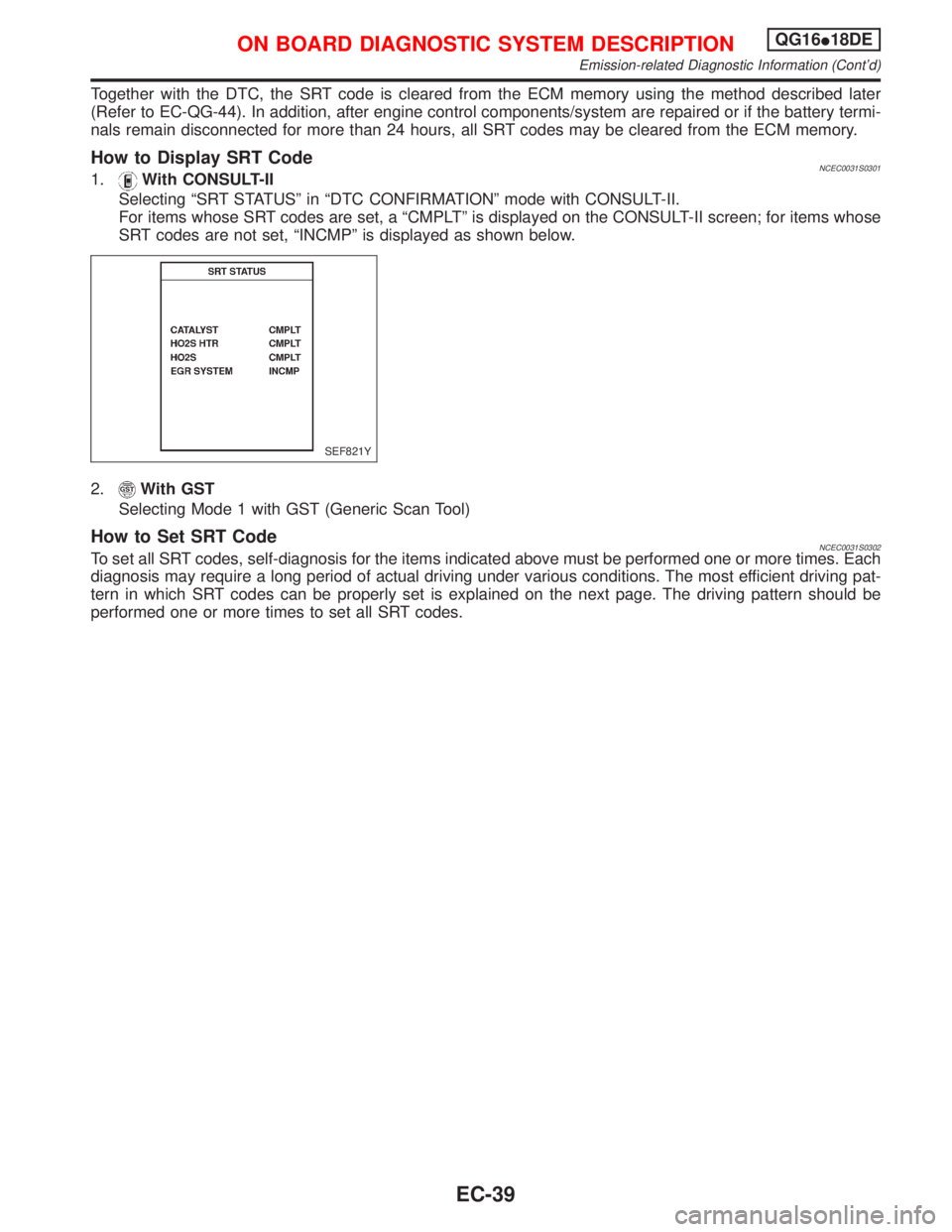
Selecting ªSRT STATUSº in ªDTC CONFIRMATIONº mode with CONSULT-II.
For items whose SRT codes are set, a ªCMPLTº is displayed on the CONSULT-II screen; for items whose
SRT codes are not set, ªINCMPº is displayed as shown below.
2.
With GST
Selecting Mode 1 with GST (Generic Scan Tool)
How to Set SRT CodeNCEC0031S0302To set all SRT codes, self-diagnosis for the items indicated above must be performed one or more times. Each
diagnosis may require a long period of actual driving under various conditions. The most efficient driving pat-
tern in which SRT codes can be properly set is explained on the next page. The driving pattern should be
performed one or more times to set all SRT codes.
SEF821Y
ON BOARD DIAGNOSTIC SYSTEM DESCRIPTIONQG16I18DE
Emission-related Diagnostic Information (Cont'd)
EC-39
Page 483 of 2267
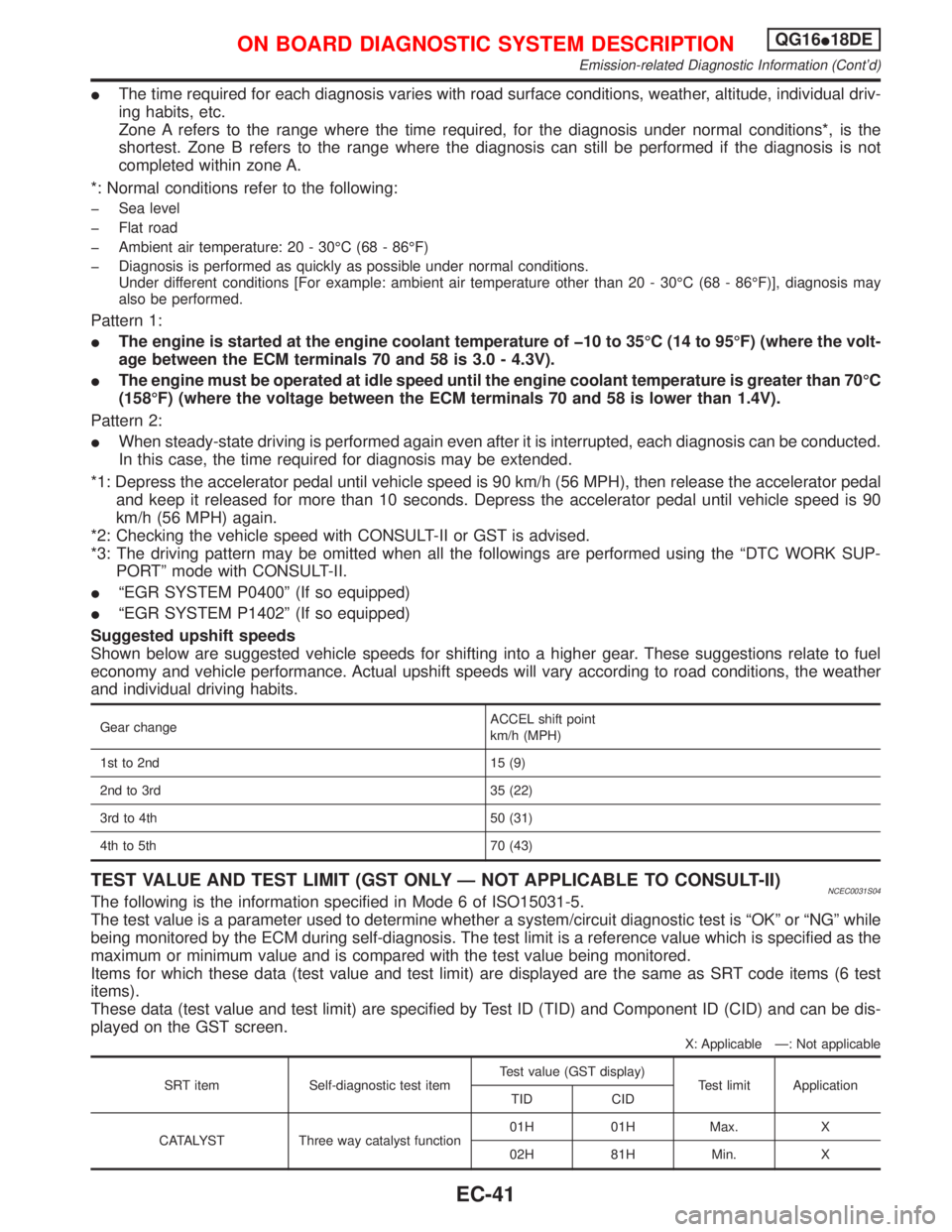
IThe time required for each diagnosis varies with road surface conditions, weather, altitude, individual driv-
ing habits, etc.
Zone A refers to the range where the time required, for the diagnosis under normal conditions*, is the
shortest. Zone B refers to the range where the diagnosis can still be performed if the diagnosis is not
completed within zone A.
*: Normal conditions refer to the following:
þ Sea level
þ Flat road
þ Ambient air temperature: 20 - 30ÉC (68 - 86ÉF)
þ Diagnosis is performed as quickly as possible under normal conditions.
Under different conditions [For example: ambient air temperature other than 20 - 30ÉC (68 - 86ÉF)], diagnosis may
also be performed.
Pattern 1:
IThe engine is started at the engine coolant temperature of þ10 to 35ÉC (14 to 95ÉF) (where the volt-
age between the ECM terminals 70 and 58 is 3.0 - 4.3V).
IThe engine must be operated at idle speed until the engine coolant temperature is greater than 70ÉC
(158ÉF) (where the voltage between the ECM terminals 70 and 58 is lower than 1.4V).
Pattern 2:
IWhen steady-state driving is performed again even after it is interrupted, each diagnosis can be conducted.
In this case, the time required for diagnosis may be extended.
*1: Depress the accelerator pedal until vehicle speed is 90 km/h (56 MPH), then release the accelerator pedal
and keep it released for more than 10 seconds. Depress the accelerator pedal until vehicle speed is 90
km/h (56 MPH) again.
*2: Checking the vehicle speed with CONSULT-II or GST is advised.
*3: The driving pattern may be omitted when all the followings are performed using the ªDTC WORK SUP-
PORTº mode with CONSULT-II.
IªEGR SYSTEM P0400º (If so equipped)
IªEGR SYSTEM P1402º (If so equipped)
Suggested upshift speeds
Shown below are suggested vehicle speeds for shifting into a higher gear. These suggestions relate to fuel
economy and vehicle performance. Actual upshift speeds will vary according to road conditions, the weather
and individual driving habits.
Gear changeACCEL shift point
km/h (MPH)
1st to 2nd 15 (9)
2nd to 3rd 35 (22)
3rd to 4th 50 (31)
4th to 5th 70 (43)
TEST VALUE AND TEST LIMIT (GST ONLY Ð NOT APPLICABLE TO CONSULT-II)NCEC0031S04The following is the information specified in Mode 6 of ISO15031-5.
The test value is a parameter used to determine whether a system/circuit diagnostic test is ªOKº or ªNGº while
being monitored by the ECM during self-diagnosis. The test limit is a reference value which is specified as the
maximum or minimum value and is compared with the test value being monitored.
Items for which these data (test value and test limit) are displayed are the same as SRT code items (6 test
items).
These data (test value and test limit) are specified by Test ID (TID) and Component ID (CID) and can be dis-
played on the GST screen.
X: Applicable Ð: Not applicable
SRT item Self-diagnostic test itemTest value (GST display)
Test limit Application
TID CID
CATALYST Three way catalyst function01H 01H Max. X
02H 81H Min. X
ON BOARD DIAGNOSTIC SYSTEM DESCRIPTIONQG16I18DE
Emission-related Diagnostic Information (Cont'd)
EC-41
Page 492 of 2267
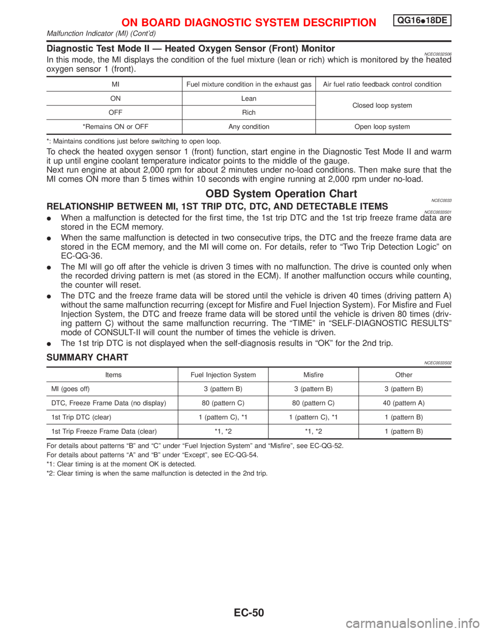
Diagnostic Test Mode II Ð Heated Oxygen Sensor (Front) MonitorNCEC0032S06In this mode, the MI displays the condition of the fuel mixture (lean or rich) which is monitored by the heated
oxygen sensor 1 (front).
MI Fuel mixture condition in the exhaust gas Air fuel ratio feedback control condition
ON Lean
Closed loop system
OFF Rich
*Remains ON or OFF Any condition Open loop system
*: Maintains conditions just before switching to open loop.
To check the heated oxygen sensor 1 (front) function, start engine in the Diagnostic Test Mode II and warm
it up until engine coolant temperature indicator points to the middle of the gauge.
Next run engine at about 2,000 rpm for about 2 minutes under no-load conditions. Then make sure that the
MI comes ON more than 5 times within 10 seconds with engine running at 2,000 rpm under no-load.
OBD System Operation ChartNCEC0033RELATIONSHIP BETWEEN MI, 1ST TRIP DTC, DTC, AND DETECTABLE ITEMSNCEC0033S01IWhen a malfunction is detected for the first time, the 1st trip DTC and the 1st trip freeze frame data are
stored in the ECM memory.
IWhen the same malfunction is detected in two consecutive trips, the DTC and the freeze frame data are
stored in the ECM memory, and the MI will come on. For details, refer to ªTwo Trip Detection Logicº on
EC-QG-36.
IThe MI will go off after the vehicle is driven 3 times with no malfunction. The drive is counted only when
the recorded driving pattern is met (as stored in the ECM). If another malfunction occurs while counting,
the counter will reset.
IThe DTC and the freeze frame data will be stored until the vehicle is driven 40 times (driving pattern A)
without the same malfunction recurring (except for Misfire and Fuel Injection System). For Misfire and Fuel
Injection System, the DTC and freeze frame data will be stored until the vehicle is driven 80 times (driv-
ing pattern C) without the same malfunction recurring. The ªTIMEº in ªSELF-DIAGNOSTIC RESULTSº
mode of CONSULT-II will count the number of times the vehicle is driven.
IThe 1st trip DTC is not displayed when the self-diagnosis results in ªOKº for the 2nd trip.
SUMMARY CHARTNCEC0033S02
Items Fuel Injection System Misfire Other
MI (goes off) 3 (pattern B) 3 (pattern B) 3 (pattern B)
DTC, Freeze Frame Data (no display) 80 (pattern C) 80 (pattern C) 40 (pattern A)
1st Trip DTC (clear) 1 (pattern C), *1 1 (pattern C), *1 1 (pattern B)
1st Trip Freeze Frame Data (clear) *1, *2 *1, *2 1 (pattern B)
For details about patterns ªBº and ªCº under ªFuel Injection Systemº and ªMisfireº, see EC-QG-52.
For details about patterns ªAº and ªBº under ªExceptº, see EC-QG-54.
*1: Clear timing is at the moment OK is detected.
*2: Clear timing is when the same malfunction is detected in the 2nd trip.
ON BOARD DIAGNOSTIC SYSTEM DESCRIPTIONQG16I18DE
Malfunction Indicator (MI) (Cont'd)
EC-50
Page 498 of 2267
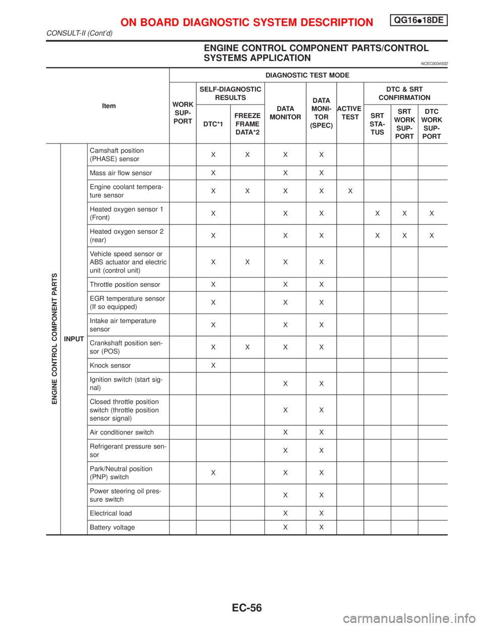
ENGINE CONTROL COMPONENT PARTS/CONTROL
SYSTEMS APPLICATION
NCEC0034S02
ItemDIAGNOSTIC TEST MODE
WORK
SUP-
PORTSELF-DIAGNOSTIC
RESULTS
D ATA
MONITORD ATA
MONI-
TOR
(SPEC)ACTIVE
TESTDTC & SRT
CONFIRMATION
DTC*1FREEZE
FRAME
DATA*2SRT
STA-
TUSSRT
WORK
SUP-
PORTDTC
WORK
SUP-
PORT
ENGINE CONTROL COMPONENT PARTS
INPUTCamshaft position
(PHASE) sensorXX X X
Mass air flow sensor X X X
Engine coolant tempera-
ture sensorXX X XX
Heated oxygen sensor 1
(Front)X X X XXX
Heated oxygen sensor 2
(rear)X X X XXX
Vehicle speed sensor or
ABS actuator and electric
unit (control unit)XX X X
Throttle position sensor X X X
EGR temperature sensor
(If so equipped)XXX
Intake air temperature
sensorXXX
Crankshaft position sen-
sor (POS)XX X X
Knock sensor X
Ignition switch (start sig-
nal)XX
Closed throttle position
switch (throttle position
sensor signal)XX
Air conditioner switch X X
Refrigerant pressure sen-
sorXX
Park/Neutral position
(PNP) switchXXX
Power steering oil pres-
sure switchXX
Electrical load X X
Battery voltage X X
ON BOARD DIAGNOSTIC SYSTEM DESCRIPTIONQG16I18DE
CONSULT-II (Cont'd)
EC-56
Page 499 of 2267
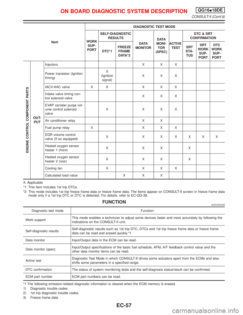
ItemDIAGNOSTIC TEST MODE
WORK
SUP-
PORTSELF-DIAGNOSTIC
RESULTS
D ATA
MONITORD ATA
MONI-
TOR
(SPEC)ACTIVE
TESTDTC & SRT
CONFIRMATION
DTC*1FREEZE
FRAME
DATA*2SRT
STA-
TUSSRT
WORK
SUP-
PORTDTC
WORK
SUP-
PORT
ENGINE CONTROL COMPONENT PARTS
OUT-
PUTInjectors X X X
Power transistor (Ignition
timing)X
(Ignition
signal)XXX
IACV-AAC valve X X X X X
Intake valve timing con-
trol solenoid valveXXX
EVAP canister purge vol-
ume control solenoid
valveXXXX
Air conditioner relay X X
Fuel pump relay X X X X
EGR volume control
valve (If so equipped)X X X XXXX
Heated oxygen sensor
heater 1 (front)XXXX
Heated oxygen sensor
heater 2 (rear)XXXX
Cooling fan X X X X
Calculated load value X X X
X: Applicable
*1: This item includes 1st trip DTCs.
*2: This mode includes 1st trip freeze frame data or freeze frame data. The items appear on CONSULT-II screen in freeze frame data
mode only if a 1st trip DTC or DTC is detected. For details, refer to EC-QG-38.
FUNCTIONNCEC0034S03
Diagnostic test mode Function
Work supportThis mode enables a technician to adjust some devices faster and more accurately by following the
indications on the CONSULT-II unit.
Self-diagnostic resultsSelf-diagnostic results such as 1st trip DTC, DTCs and 1st trip freeze frame data or freeze frame
data can be read and erased quickly.*1
Data monitor Input/Output data in the ECM can be read.
Data monitor (spec)Input/Output specifications of the basic fuel schedule, AFM, A/F feedback control value and the
other data monitor items can be read.
Active testDiagnostic Test Mode in which CONSULT-II drives some actuators apart from the ECMs and also
shifts some parameters in a specified range.
DTC confirmation The status of system monitoring tests and the self-diagnosis status/result can be confirmed.
ECM part number ECM part numbers can be read.
*1 The following emission-related diagnostic information is cleared when the ECM memory is erased.
1) Diagnostic trouble codes
2) 1st trip diagnostic trouble codes
3) Freeze frame data
ON BOARD DIAGNOSTIC SYSTEM DESCRIPTIONQG16I18DE
CONSULT-II (Cont'd)
EC-57