1999 NISSAN PRIMERA torque
[x] Cancel search: torquePage 1786 of 2267
INSTALLATION
Installation is reverse procedure of removal.
CAUTION:
lAlways use a new top plate seal.
lUse the alignment marks to position the top plate.
lTighten to specified torque.
FUEL SYSTEM
Fuel Pump and Gauge (Cont'd)
FE-8
Page 1796 of 2267
GENERAL INFORMATION
SECTION
GI
CONTENTS
MODIFICATIONS........................................................... 2
PRECAUTIONS............................................................. 3
Supplemental Restraint System (SRS)²AIR
BAG²and²SEAT BELT PRE-TENSIONER²............. 3
Precautions for NATS ................................................ 3
Precautions for Super Lock System .......................... 4
General Precautions .................................................. 4
Precautions for Multiport Fuel Injection System
or Engine Control Module.......................................... 6
Precautions for Three Way Catalyst.......................... 6
Precautions for Turbocharger .................................... 6
Precautions for Engine Oils ....................................... 6
Precautions for Fuel .................................................. 7
Precautions for Air Conditioning ................................ 8
HOW TO USE THIS MANUAL...................................... 9
HOW TO READ WIRING DIAGRAMS......................... 11
Sample/Wiring Diagram - EXAMPL - ....................... 11
Description ............................................................... 13
Wiring Diagram Codes (Cell Codes) ....................... 20
HOW TO CHECK TERMINAL..................................... 21
How to Probe Connectors ....................................... 21
How to Check Enlarged Contact Spring of
Terminal ................................................................... 22
Waterproof Connector Inspection ............................ 23
Terminal Lock Inspection ......................................... 23HOW TO PERFORM EFFICIENT DIAGNOSIS FOR
AN ELECTRICAL INCIDENT...................................... 24
Work Flow ................................................................ 24
Incident Simulation Tests ......................................... 25
Circuit Inspection ..................................................... 29
HOW TO FOLLOW TROUBLE DIAGNOSES............ 35
How to Follow Test Groups in Trouble Diagnoses .. 35
CONSULT-II CHECKING SYSTEM............................. 39
Function and System Application ............................ 39
Nickel Metal Hydride Battery Replacement............. 39
Checking Equipment................................................ 39
CONSULT-II Data Link Connector (DLC) Circuit .... 40
IDENTIFICATION INFORMATION............................... 41
Model Variation ........................................................ 41
Identification Number ............................................... 43
Dimensions .............................................................. 45
Wheels and Tires ..................................................... 45
LIFTING POINTS AND TOW TRUCK TOWING......... 46
Preparation .............................................................. 46
Board-on Lift ............................................................ 46
Garage Jack and Safety Stand ............................... 47
2-pole Lift ................................................................. 48
Tow Truck Towing .................................................... 49
TIGHTENING TORQUE OF STANDARD BOLTS...... 50
ISO 15031-2 TERMINOLOGY LIST............................ 51
ISO 15031-2 Terminology List ................................. 51
GI
Page 1804 of 2267
lALPHABETICAL INDEXis provided at the end of this manual so that you can rapidly find the item and
page you are searching for.
lA QUICK REFERENCE INDEX,a black tab (e.g.) is provided on the first page. You can quickly
find the first page of each section by mating it to the section's black tab.
lTHE CONTENTSare listed on the first page of each section.
lTHE TITLEis indicated on the upper portion of each page and shows the part or system.
lTHE PAGE NUMBERof each section consists of two letters which designate the particular section and
a number (e.g. ªBR-5º).
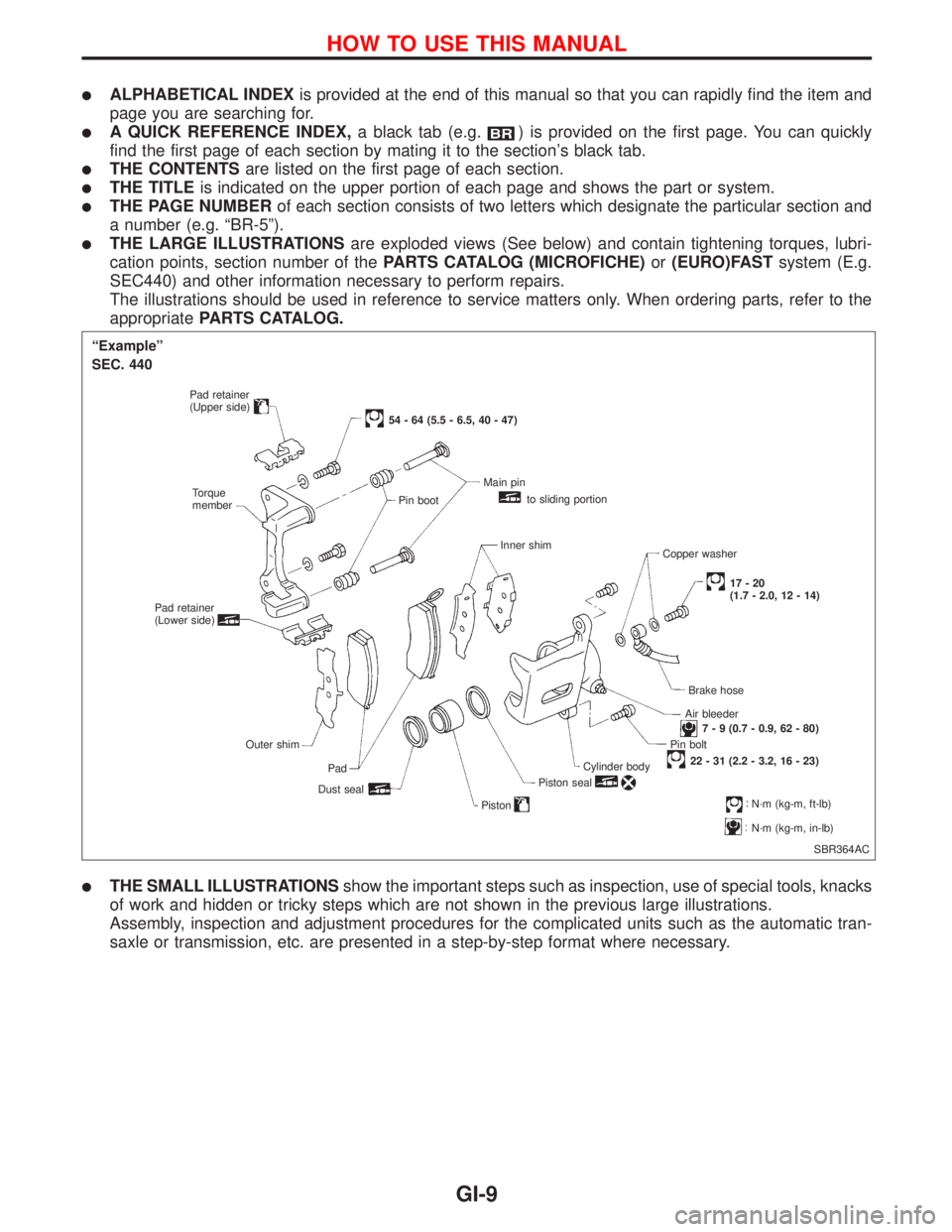
lTHE LARGE ILLUSTRATIONSare exploded views (See below) and contain tightening torques, lubri-
cation points, section number of thePARTS CATALOG (MICROFICHE)or(EURO)FASTsystem (E.g.
SEC440) and other information necessary to perform repairs.
The illustrations should be used in reference to service matters only. When ordering parts, refer to the
appropriatePARTS CATALOG.
lTHE SMALL ILLUSTRATIONSshow the important steps such as inspection, use of special tools, knacks
of work and hidden or tricky steps which are not shown in the previous large illustrations.
Assembly, inspection and adjustment procedures for the complicated units such as the automatic tran-
saxle or transmission, etc. are presented in a step-by-step format where necessary.
SBR364AC
ªExampleº
SEC. 440
Pad retainer
(Upper side)
Torque
member
Pad retainer
(Lower side)
Outer shim
Pad
Dust seal
54 - 64 (5.5 - 6.5, 40 - 47)
Pin bootMain pin
to sliding portion
Inner shim
Copper washer
17-20
(1.7 - 2.0, 12 - 14)
Brake hose
Air bleeder
7 - 9 (0.7 - 0.9, 62 - 80)
Pin bolt
22 - 31 (2.2 - 3.2, 16 - 23)
Cylinder body
Piston seal
PistonN´m (kg-m, ft-lb)
N´m (kg-m, in-lb)
HOW TO USE THIS MANUAL
GI-9
Page 1805 of 2267
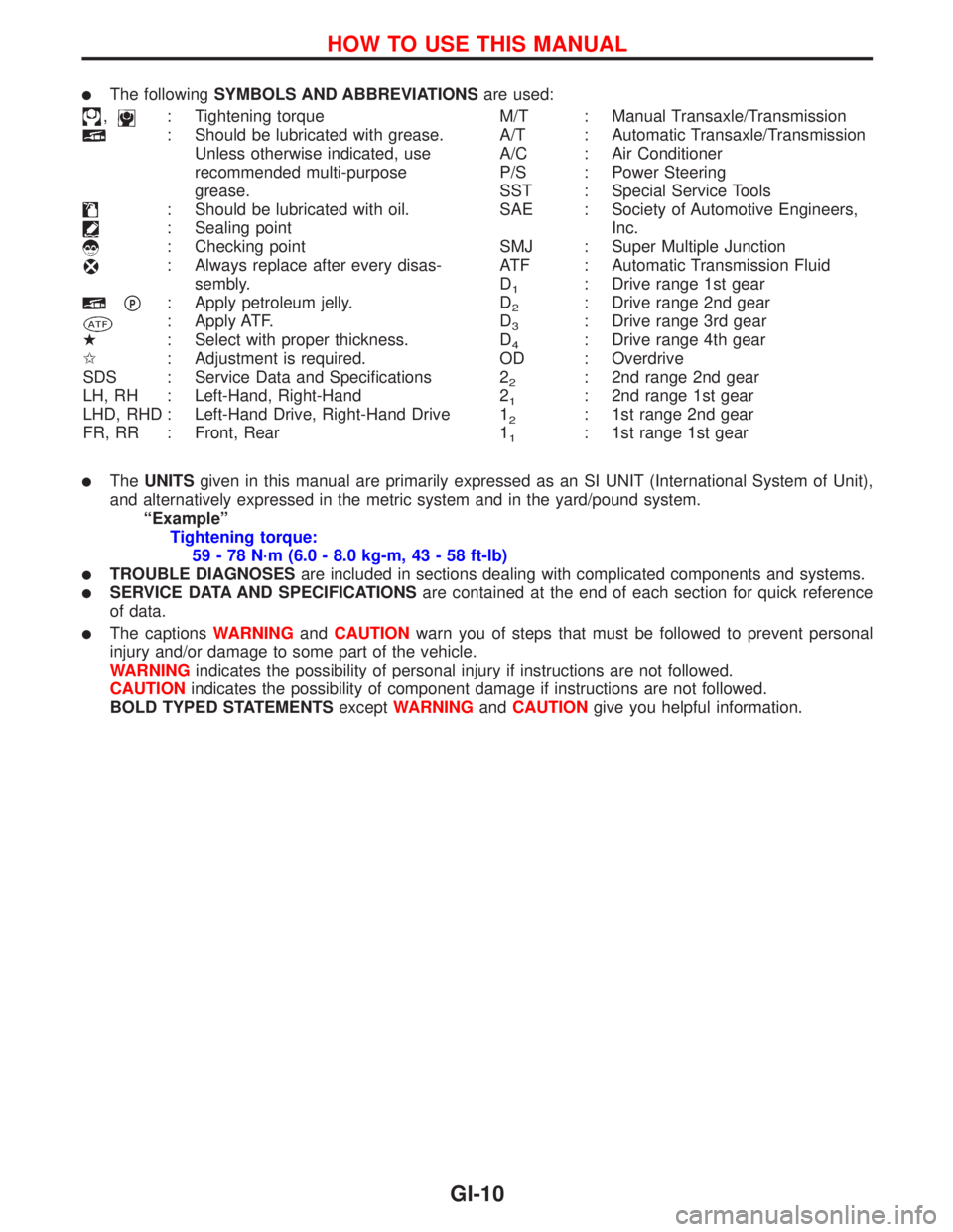
lThe followingSYMBOLS AND ABBREVIATIONSare used:
,: Tightening torque
: Should be lubricated with grease.
Unless otherwise indicated, use
recommended multi-purpose
grease.
: Should be lubricated with oil.
: Sealing point
: Checking point
: Always replace after every disas-
sembly.
pP: Apply petroleum jelly.
: Apply ATF.
H: Select with proper thickness.
I: Adjustment is required.
SDS : Service Data and Specifications
LH, RH : Left-Hand, Right-Hand
LHD, RHD : Left-Hand Drive, Right-Hand Drive
FR, RR : Front, RearM/T : Manual Transaxle/Transmission
A/T : Automatic Transaxle/Transmission
A/C : Air Conditioner
P/S : Power Steering
SST : Special Service Tools
SAE : Society of Automotive Engineers,
Inc.
SMJ : Super Multiple Junction
ATF : Automatic Transmission Fluid
D
1: Drive range 1st gear
D
2: Drive range 2nd gear
D
3: Drive range 3rd gear
D
4: Drive range 4th gear
OD : Overdrive
2
2: 2nd range 2nd gear
2
1: 2nd range 1st gear
1
2: 1st range 2nd gear
1
1: 1st range 1st gear
lTheUNITSgiven in this manual are primarily expressed as an SI UNIT (International System of Unit),
and alternatively expressed in the metric system and in the yard/pound system.
ªExampleº
Tightening torque:
59 - 78 N´m (6.0 - 8.0 kg-m, 43 - 58 ft-lb)
lTROUBLE DIAGNOSESare included in sections dealing with complicated components and systems.
lSERVICE DATA AND SPECIFICATIONSare contained at the end of each section for quick reference
of data.
lThe captionsWARNINGandCAUTIONwarn you of steps that must be followed to prevent personal
injury and/or damage to some part of the vehicle.
WARNINGindicates the possibility of personal injury if instructions are not followed.
CAUTIONindicates the possibility of component damage if instructions are not followed.
BOLD TYPED STATEMENTSexceptWARNINGandCAUTIONgive you helpful information.
HOW TO USE THIS MANUAL
GI-10
Page 1815 of 2267
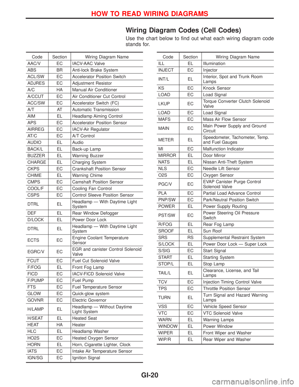
Wiring Diagram Codes (Cell Codes)
Use the chart below to find out what each wiring diagram code
stands for.
Code Section Wiring Diagram Name
AAC/V EC IACV-AAC Valve
ABS BR Anti-lock Brake System
ACL/SW EC Accelerator Position Switch
ADJRES EC Adjustment Resistor
A/C HA Manual Air Conditioner
A/CCUT EC Air Conditioner Cut Control
ACC/SW EC Accelerator Switch (FC)
A/T AT Automatic Transmission
AIM EL Headlamp Aiming Control
APS EC Accelerator Position Sensor
AIRREG EC IACV-Air Regulator
AT/C EC A/T Control
AUDIO EL Audio
BACK/L EL Back-up Lamp
BUZZER EL Warning Buzzer
CHARGE EL Charging System
CKPS EC Crankshaft Position Sensor
CHIME EL Warning Chime
CMPS EC Camshaft Position Sensor
COOL/F EC Cooling Fan Control
CSPS EC Control Sleeve Position Sensor
DTRL ELHeadlamp Ð With Daytime Light
System
DEF EL Rear Window Defogger
D/LOCK EL Power Door Lock
DTRL ELHeadlamp Ð With Daytime Light
System
ECTS ECEngine Coolant Temperature
Sensor
EGRC/V ECEGR and canister Control Solenoid
Valve
FCUT EC Fuel Cut Solenoid Valve
F/FOG EL Front Fog Lamp
FICD EC IACV-FICD Solenoid Valve
F/PUMP EC Fuel Pump
FTS EC Fuel Temperature Sensor
GLOW EC Quick-glow system
GOVNR EC Electric Governor
H/LAMP ELHeadlamp Ð Without Daytime
Light System
H/SEAT EL Heated Seat
HEAT HA Heater
HLC EL Headlamp Washer
HO2S EC Heated Oxygen Sensor
HORN EL Horn, Cigarette Lighter, Clock
IATS EC Intake Air Temperature Sensor
IGN/SG EC Ignition SignalCode Section Wiring Diagram Name
ILL EL Illumination
INJECT EC Injector
INT/L ELInterior, Spot and Trunk Room
Lamps
KS EC Knock Sensor
LOAD EC Load Signal
LKUP ECTorque Converter Clutch Solenoid
Valve
LOAD EC Load Signal
MAFS EC Mass Air Flow Sensor
MAIN ECMain Power Supply and Ground
Circuit
METER ELSpeedometer, Tachometer, Temp.
and Fuel Gauges
MI EC Malfunction Indicator
MIRROR EL Door Mirror
NATS EL Nissan Anti-Theft System
NLS EC Needle Lift Sensor
O2S EC Oxygen Sensor
PGC/V ECEVAP Canister Purge Control
Solenoid Valve
PLA EC Partial Load Advance Control
PNP/SW EC Park/Neutral Position Switch
POWER EL Power Supply Routing
PST/SW ECPower Steering Oil Pressure
Switch
R/FOG EL Rear Fog Lamp
SROOF EL Sun Roof
SRS RS Supplemental Restraint System
S/LOCK EL Power Door Lock Ð Super Lock
S/SIG EC Start Signal
START EL Starting System
STOP/L EL Stop Lamp
TAIL/L ELClearance, License, and Tail
Lamps
TCV EC Injection Timing Control Valve
TPS EC Throttle Position Sensor
TURN ELTurn Signal and Hazard Warning
Lamps
VSS EC Vehicle Speed Sensor
VTC EC VTC Solenoid Valve
WARN EL Warning Lamps
WINDOW EL Power Window
WIPER EL Front Wiper and Washer
WIP/R EL Rear Wiper and Washer
HOW TO READ WIRING DIAGRAMS
GI-20
Page 1845 of 2267
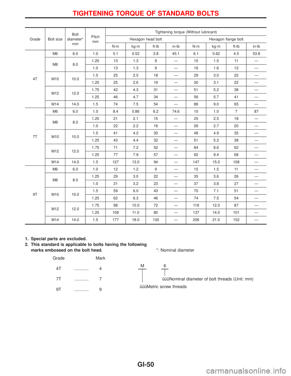
Grade Bolt sizeBolt
diameter*
mmPitch
mmTightening torque (Without lubricant)
Hexagon head bolt Hexagon flange bolt
N´m kg-m ft-lb in-lb N´m kg-m ft-lb in-lb
4TM6 6.0 1.0 5.1 0.52 3.8 45.1 6.1 0.62 4.5 53.8
M8 8.01.25 13 1.3 9 Ð 15 1.5 11 Ð
1.0 13 1.3 9 Ð 16 1.6 12 Ð
M10 10.01.5 25 2.5 18 Ð 29 3.0 22 Ð
1.25 25 2.6 19 Ð 30 3.1 22 Ð
M12 12.01.75 42 4.3 31 Ð 51 5.2 38 Ð
1.25 46 4.7 34 Ð 56 5.7 41 Ð
M14 14.0 1.5 74 7.5 54 Ð 88 9.0 65 Ð
7TM6 6.0 1.0 8.4 0.86 6.2 74.6 10 1.0 7 87
M8 8.01.25 21 2.1 15 Ð 25 2.5 18 Ð
1.0 22 2.2 16 Ð 26 2.7 20 Ð
M10 10.01.5 41 4.2 30 Ð 48 4.9 35 Ð
1.25 43 4.4 32 Ð 51 5.2 38 Ð
M12 12.01.75 71 7.2 52 Ð 84 8.6 62 Ð
1.25 77 7.9 57 Ð 92 9.4 68 Ð
M14 14.0 1.5 127 13.0 94 Ð 147 15.0 108 Ð
9TM6 6.0 1.0 12 1.2 9 Ð 15 1.5 11 Ð
M8 8.01.25 29 3.0 22 Ð 35 3.6 26 Ð
1.0 31 3.2 23 Ð 37 3.8 27 Ð
M10 10.01.5 59 6.0 43 Ð 70 7.1 51 Ð
1.25 62 6.3 46 Ð 74 7.5 54 Ð
M12 12.01.75 98 10.0 72 Ð 118 12.0 87 Ð
1.25 108 11.0 80 Ð 137 14.0 101 Ð
M14 14.0 1.5 177 18.0 130 Ð 206 21.0 152 Ð
1. Special parts are excluded.
2. This standard is applicable to bolts having the following
marks embossed on the bolt head.*: Nominal diameter
Grade Mark
4T ............ 4M
6
7T ............ 7 îîîNominal diameter of bolt threads (Unit: mm)
9T ............ 9îîîMetric screw threads
TIGHTENING TORQUE OF STANDARD BOLTS
GI-50
Page 1849 of 2267

***: Not applicable
NEW TERMNEW ACRONYM /
ABBREVIATIONOLD TERM
Three way + oxidation catalytic converter
systemTWC + OC system ***
Throttle body TB Throttle chamber
SPI body
Throttle body fuel injection system TBI system Fuel injection control
Throttle position TP Throttle position
Throttle position sensor TPS Throttle sensor
Throttle position switch TP switch Throttle switch
Torque converter clutch solenoid valve TCC solenoid valve Lock-up cancel solenoid
Lock-up solenoid
Turbocharger TC Turbocharger
Vacuum cut valve *** Vacuum control valve
Vacuum cut valve bypass valve *** ***
Vehicle speed sensor VSS Vehicle speed sensor
Volume air flow sensor VAFS Air flow meter
Warm up oxidation catalyst WU-OC Catalyst
Warm up oxidation catalytic converter system WU-OC system ***
Warm up three way catalyst WU-TWC Catalyst
Warm up three way catalytic converter sys-
temWU-TWC system ***
Wide open throttle position switch WOTP switch Full switch
ISO 15031-2 TERMINOLOGY LIST
ISO 15031-2 Terminology List (Cont'd)
GI-54
Page 1855 of 2267
WARNING:
Make sure all refrigerant is discharged into the recycling equipment and the pressure in the system
is less than atmospheric pressure. Then gradually loosen the discharge side hose fitting and remove
it.
CAUTION:
When replacing or cleaning refrigerant cycle components, observe the following:
lWhen the compressor is removed, store it in the same position as it is when mounted on the car.
Failure to do so will cause lubricant to enter the low pressure chamber.
lWhen connecting tubes, always use a torque wrench and a back-up wrench.
lAfter disconnecting tubes, immediately plug all openings to prevent entry of dirt and moisture.
lWhen installing an air conditioner in the vehicle, connect the pipes as the final stage of the
operation. Do not remove the seal caps of pipes and other components until just before connec-
tion.
lAllow components stored in cool areas to warm to ambient temperature before removing seal
caps. This prevents condensation from forming inside A/C components.
lThoroughly remove moisture from the refrigeration system before charging the refrigerant.
lAlways replace used O-rings.
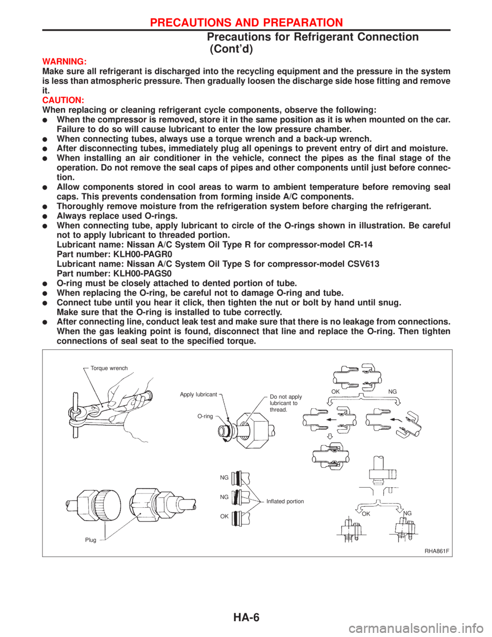
lWhen connecting tube, apply lubricant to circle of the O-rings shown in illustration. Be careful
not to apply lubricant to threaded portion.
Lubricant name: Nissan A/C System Oil Type R for compressor-model CR-14
Part number: KLH00-PAGR0
Lubricant name: Nissan A/C System Oil Type S for compressor-model CSV613
Part number: KLH00-PAGS0
lO-ring must be closely attached to dented portion of tube.
lWhen replacing the O-ring, be careful not to damage O-ring and tube.
lConnect tube until you hear it click, then tighten the nut or bolt by hand until snug.
Make sure that the O-ring is installed to tube correctly.
lAfter connecting line, conduct leak test and make sure that there is no leakage from connections.
When the gas leaking point is found, disconnect that line and replace the O-ring. Then tighten
connections of seal seat to the specified torque.
RHA861F Torque wrench
Apply lubricant
Do not apply
lubricant to
thread.NG OK
NG
OK Inflated portion NG
NG
OK
PlugO-ring
PRECAUTIONS AND PREPARATION
Precautions for Refrigerant Connection
(Cont'd)
HA-6