Page 1641 of 2267
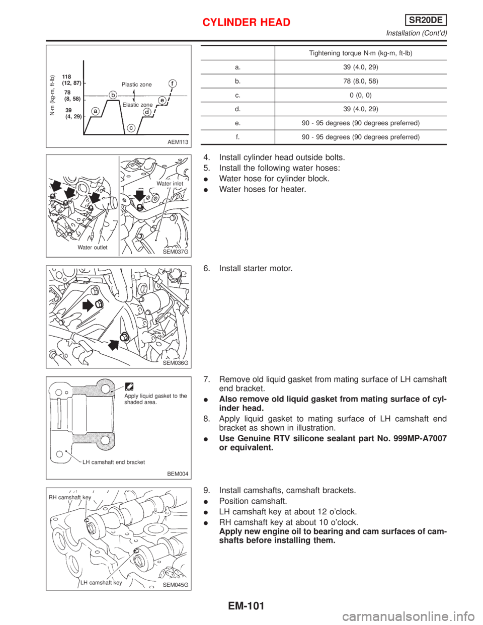
Tightening torque N×m (kg-m, ft-lb)
a. 39 (4.0, 29)
b. 78 (8.0, 58)
c. 0 (0, 0)
d. 39 (4.0, 29)
e. 90 - 95 degrees (90 degrees preferred)
f. 90 - 95 degrees (90 degrees preferred)
4. Install cylinder head outside bolts.
5. Install the following water hoses:
IWater hose for cylinder block.
IWater hoses for heater.
6. Install starter motor.
7. Remove old liquid gasket from mating surface of LH camshaft
end bracket.
IAlso remove old liquid gasket from mating surface of cyl-
inder head.
8. Apply liquid gasket to mating surface of LH camshaft end
bracket as shown in illustration.
IUse Genuine RTV silicone sealant part No. 999MP-A7007
or equivalent.
9. Install camshafts, camshaft brackets.
IPosition camshaft.
ILH camshaft key at about 12 o'clock.
IRH camshaft key at about 10 o'clock.
Apply new engine oil to bearing and cam surfaces of cam-
shafts before installing them.
AEM113
N´m (kg-m, ft-lb)
11 8
(12, 87)
78
(8, 58)
39
(4, 29)Plastic zone
Elastic zone
SEM037G Water outletWater inlet
SEM036G
BEM004 Apply liquid gasket to the
shaded area.
LH camshaft end bracket
SEM045G RH camshaft key
LH camshaft key
CYLINDER HEADSR20DE
Installation (Cont'd)
EM-101
Page 1643 of 2267
ILock camshafts as shown in figure and tighten to specified
torque.
: 137 - 157 N×m (14.0 - 16.0 kg-m, 101 - 116 ft-lb)
Apply new engine oil to threads and seating surfaces of cam-
shaft sprocket bolts before installing them.
11. Install distributor.
IMake sure that position of camshaft is as shown in figure.
IMake sure that No. 1 piston is set at TDC and that distribu-
tor rotor is set at No. 1 cylinder spark position.
12. Install chain tensioner.
Make sure the camshaft sprockets are tightened completely.
Press cam stopper down and ªpress-inº sleeve until hook can
be engaged on pin. When tensioner is bolted in position the
hook will release automatically. Make sure arrow ªAº points
toward engine front.
SEM049G
SEM050G
SEM033G Rotor head position
(No. 1 cylinder at TDC)
SEM990C
SEM991C
CYLINDER HEADSR20DE
Installation (Cont'd)
EM-103
Page 1653 of 2267
6. Cylinder bore size is determined by adding piston-to-bore
clearance to piston diameter ªAº.
Rebored size calculation:
D= A+BþC
where,
D: Bored diameter
A: Piston diameter as measured
B: Piston-to-bore clearance
C: Honing allowance 0.02 mm (0.0008 in)
7. Install main bearing caps, and tighten to the specified torque.
IOtherwise, cylinder bores may be distorted in final assem-
bly.
8. Cut cylinder bores.
IWhen any cylinder needs boring, all other cylinders must
also be bored.
IDo not cut too much out of cylinder bore at a time. Cut
only 0.05 mm (0.0020 in) or so in diameter at a time.
9. Hone cylinders to obtain specified piston-to-bore clearance.
10. Measure finished cylinder bore for out-of-round and taper.
IMeasurement should be done after cylinder bore cools
down.
CRANKSHAFT
1. Check crankshaft main and pin journals for score, wear or
cracks.
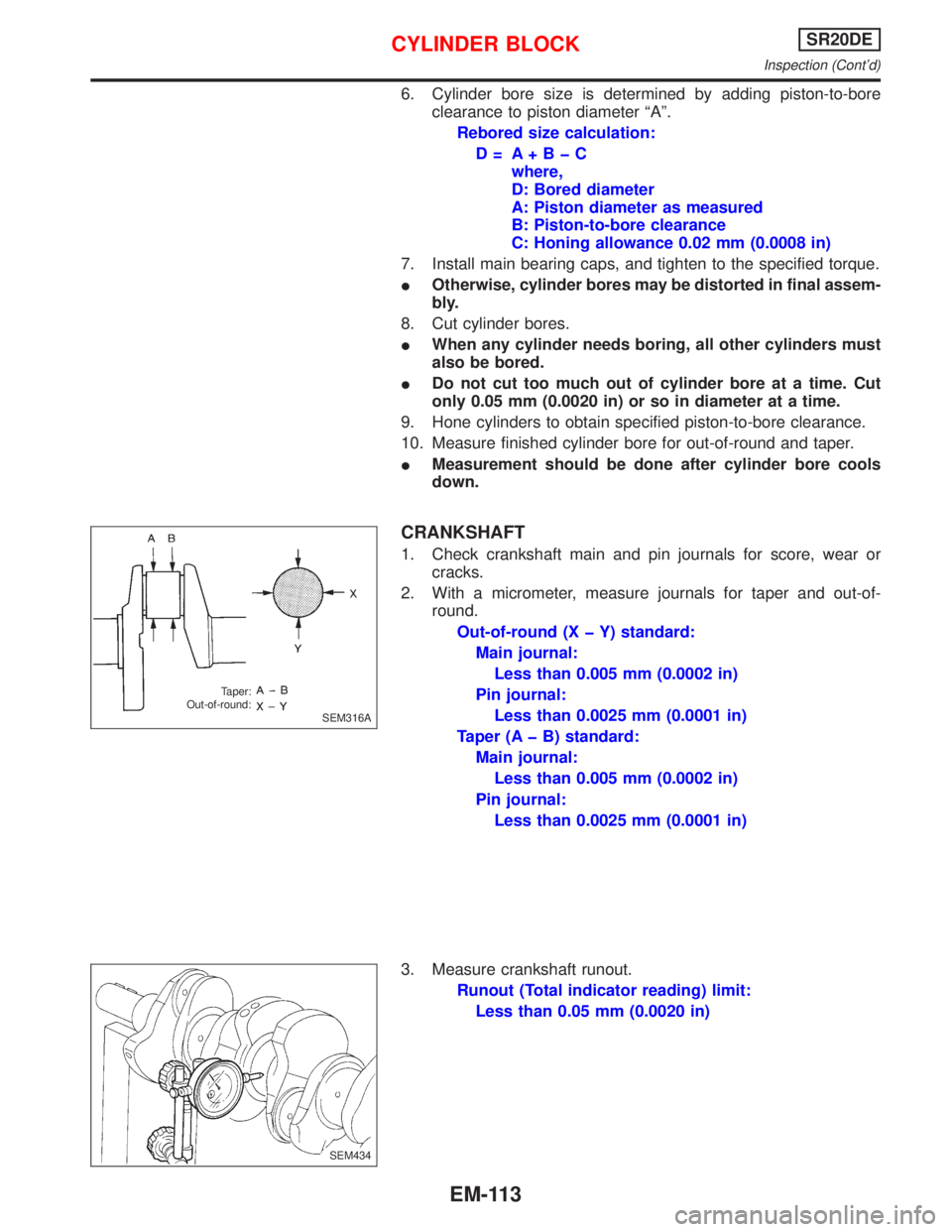
2. With a micrometer, measure journals for taper and out-of-
round.
Out-of-round (X þ Y) standard:
Main journal:
Less than 0.005 mm (0.0002 in)
Pin journal:
Less than 0.0025 mm (0.0001 in)
Taper (A þ B) standard:
Main journal:
Less than 0.005 mm (0.0002 in)
Pin journal:
Less than 0.0025 mm (0.0001 in)
3. Measure crankshaft runout.
Runout (Total indicator reading) limit:
Less than 0.05 mm (0.0020 in)
SEM316A Taper:
Out-of-round:
.SEM434
CYLINDER BLOCKSR20DE
Inspection (Cont'd)
EM-113
Page 1655 of 2267
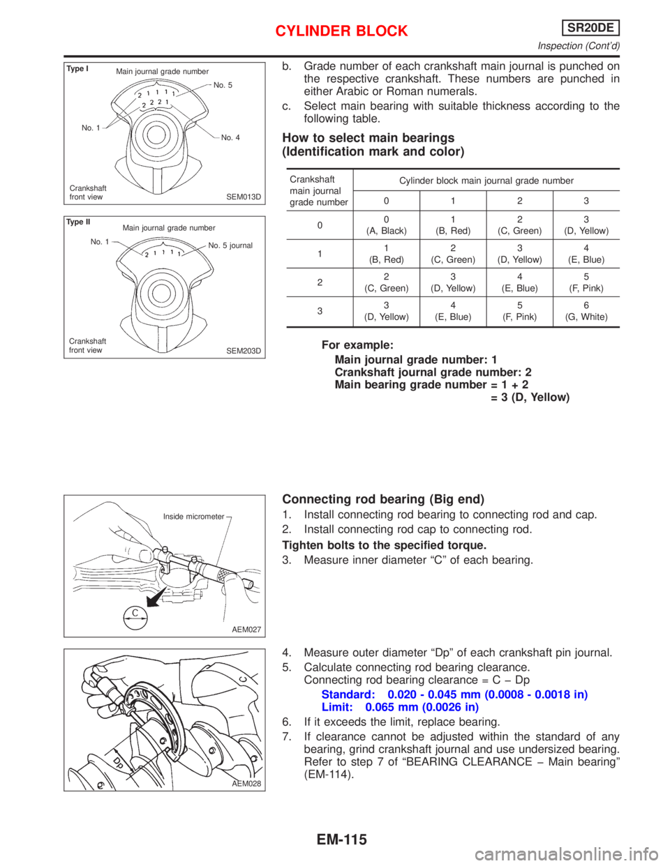
b. Grade number of each crankshaft main journal is punched on
the respective crankshaft. These numbers are punched in
either Arabic or Roman numerals.
c. Select main bearing with suitable thickness according to the
following table.
How to select main bearings
(Identification mark and color)
Crankshaft
main journal
grade numberCylinder block main journal grade number
0123
00
(A, Black)1
(B, Red)2
(C, Green)3
(D, Yellow)
11
(B, Red)2
(C, Green)3
(D, Yellow)4
(E, Blue)
22
(C, Green)3
(D, Yellow)4
(E, Blue)5
(F, Pink)
33
(D, Yellow)4
(E, Blue)5
(F, Pink)6
(G, White)
For example:
Main journal grade number: 1
Crankshaft journal grade number: 2
Main bearing grade number=1+2
= 3 (D, Yellow)
Connecting rod bearing (Big end)
1. Install connecting rod bearing to connecting rod and cap.
2. Install connecting rod cap to connecting rod.
Tighten bolts to the specified torque.
3. Measure inner diameter ªCº of each bearing.
4. Measure outer diameter ªDpº of each crankshaft pin journal.
5. Calculate connecting rod bearing clearance.
Connecting rod bearing clearance=CþDp
Standard: 0.020 - 0.045 mm (0.0008 - 0.0018 in)
Limit: 0.065 mm (0.0026 in)
6. If it exceeds the limit, replace bearing.
7. If clearance cannot be adjusted within the standard of any
bearing, grind crankshaft journal and use undersized bearing.
Refer to step 7 of ªBEARING CLEARANCE þ Main bearingº
(EM-114).
SEM013D Type I
Main journal grade number
No. 5
No. 4 No. 1
Crankshaft
front view
SEM203D Type II
Main journal grade number
No. 1
No. 5 journal
Crankshaft
front view
AEM027 Inside micrometer
AEM028
CYLINDER BLOCKSR20DE
Inspection (Cont'd)
EM-115
Page 1659 of 2267
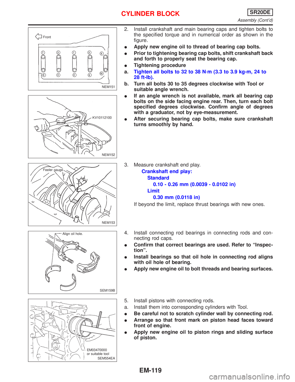
2. Install crankshaft and main bearing caps and tighten bolts to
the specified torque and in numerical order as shown in the
figure.
IApply new engine oil to thread of bearing cap bolts.
IPrior to tightening bearing cap bolts, shift crankshaft back
and forth to properly seat the bearing cap.
ITightening procedure
a.Tighten all bolts to 32 to 38 N´m (3.3 to 3.9 kg-m, 24 to
28 ft-lb).
b. Turn all bolts 30 to 35 degrees clockwise with Tool or
suitable angle wrench.
IIf an angle wrench is not available, mark all bearing cap
bolts on the side facing engine rear. Then, turn each bolt
specified degrees clockwise. Confirm angle of degrees
with a graduator, not by eye-measurement.
IAfter securing bearing cap bolts, make sure crankshaft
turns smoothly by hand.
3. Measure crankshaft end play.
Crankshaft end play:
Standard
0.10 - 0.26 mm (0.0039 - 0.0102 in)
Limit
0.30 mm (0.0118 in)
If beyond the limit, replace thrust bearings with new ones.
4. Install connecting rod bearings in connecting rods and con-
necting rod caps.
IConfirm that correct bearings are used. Refer to ªInspec-
tionº.
IInstall bearings so that oil hole in connecting rod aligns
with oil hole of bearing.
IApply new engine oil to bolt threads and bearing surfaces.
5. Install pistons with connecting rods.
a. Install them into corresponding cylinders with Tool.
IBe careful not to scratch cylinder wall by connecting rod.
IArrange so that front mark on piston head faces toward
front of engine.
IApply new engine oil to piston rings and sliding surface
of piston.
NEM151 Front
p7p3p1p5p9
p8p4p2p6p10
NEM152 KV10112100
NEM153 Feeler gauge
SEM159B Align oil hole.
SEM554EA EM03470000
or suitable tool
CYLINDER BLOCKSR20DE
Assembly (Cont'd)
EM-119
Page 1660 of 2267
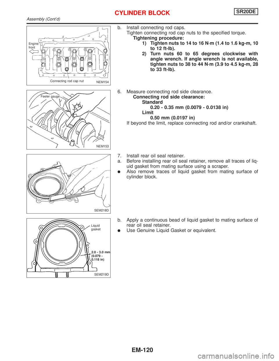
b. Install connecting rod caps.
Tighten connecting rod cap nuts to the specified torque.
Tightening procedure:
1) Tighten nuts to 14 to 16 N´m (1.4 to 1.6 kg-m, 10
to 12 ft-lb).
2) Turn nuts 60 to 65 degrees clockwise with
angle wrench. If angle wrench is not available,
tighten nuts to 38 to 44 N´m (3.9 to 4.5 kg-m, 28
to 33 ft-lb).
6. Measure connecting rod side clearance.
Connecting rod side clearance:
Standard
0.20 - 0.35 mm (0.0079 - 0.0138 in)
Limit
0.50 mm (0.0197 in)
If beyond the limit, replace connecting rod and/or crankshaft.
7. Install rear oil seal retainer.
a. Before installing rear oil seal retainer, remove all traces of liq-
uid gasket from mating surface using a scraper.
lAlso remove traces of liquid gasket from mating surface of
cylinder block.
b. Apply a continuous bead of liquid gasket to mating surface of
rear oil seal retainer.
lUse Genuine Liquid Gasket or equivalent.
NEM154 Engine
front
Connecting rod cap nut
NEM153 Feeler gauge
SEM218D
SEM219D Liquid
gasket
2.0 - 3.0 mm
(0.079 -
0.118 in)
CYLINDER BLOCKSR20DE
Assembly (Cont'd)
EM-120
Page 1674 of 2267
Belt tensioner, tensioner spring and idler
1. Check belt tensioner and idler for smooth turning.
2. Check condition of tensioner spring.
Crankshaft sprocket and front camshaft sprocket
Check teeth for abnormal signs.
Installation
1. Confirm that No. 1 piston is set at TDC on its compression
stroke. (TDC is indicated by crankshaft pulley notch without
painted mark.)
2. Install tensioner and return spring.
Temporarily tighten bolts so that tensioner is set at the fully
outside position.
3. Install idler and tighten bolt to the specified torque.
4. Install timing belt with crankshaft sprocket.
a. Align white lines on timing belt with punchmarks on
camshaft sprocket and crankshaft sprocket.
b. Point arrow on timing belt toward belt cover.
5. Install camshaft sprocket plate and secure screws with Loctite.
SEM558
SEM516D
SEM517D
SEM518D
Mark
43 cogsAlign
Align
SEM519DA
TIMING BELTCD20T
Inspection (Cont'd)
EM-134
Page 1687 of 2267
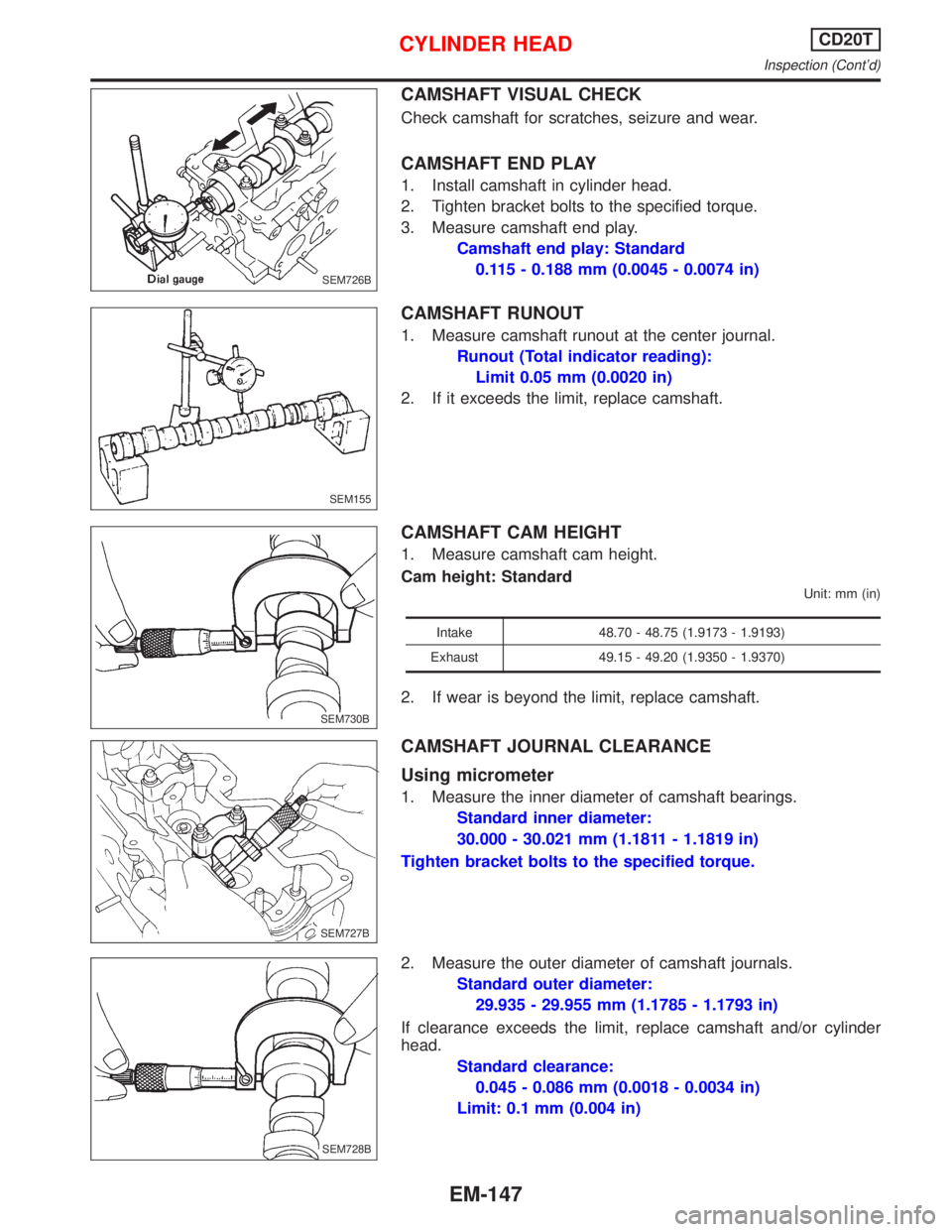
CAMSHAFT VISUAL CHECK
Check camshaft for scratches, seizure and wear.
CAMSHAFT END PLAY
1. Install camshaft in cylinder head.
2. Tighten bracket bolts to the specified torque.
3. Measure camshaft end play.
Camshaft end play: Standard
0.115 - 0.188 mm (0.0045 - 0.0074 in)
CAMSHAFT RUNOUT
1. Measure camshaft runout at the center journal.
Runout (Total indicator reading):
Limit 0.05 mm (0.0020 in)
2. If it exceeds the limit, replace camshaft.
CAMSHAFT CAM HEIGHT
1. Measure camshaft cam height.
Cam height: Standard
Unit: mm (in)
Intake 48.70 - 48.75 (1.9173 - 1.9193)
Exhaust 49.15 - 49.20 (1.9350 - 1.9370)
2. If wear is beyond the limit, replace camshaft.
CAMSHAFT JOURNAL CLEARANCE
Using micrometer
1. Measure the inner diameter of camshaft bearings.
Standard inner diameter:
30.000 - 30.021 mm (1.1811 - 1.1819 in)
Tighten bracket bolts to the specified torque.
2. Measure the outer diameter of camshaft journals.
Standard outer diameter:
29.935 - 29.955 mm (1.1785 - 1.1793 in)
If clearance exceeds the limit, replace camshaft and/or cylinder
head.
Standard clearance:
0.045 - 0.086 mm (0.0018 - 0.0034 in)
Limit: 0.1 mm (0.004 in)
SEM726B
SEM155
.SEM730B
.SEM727B
SEM728B
CYLINDER HEADCD20T
Inspection (Cont'd)
EM-147