Page 164 of 2267
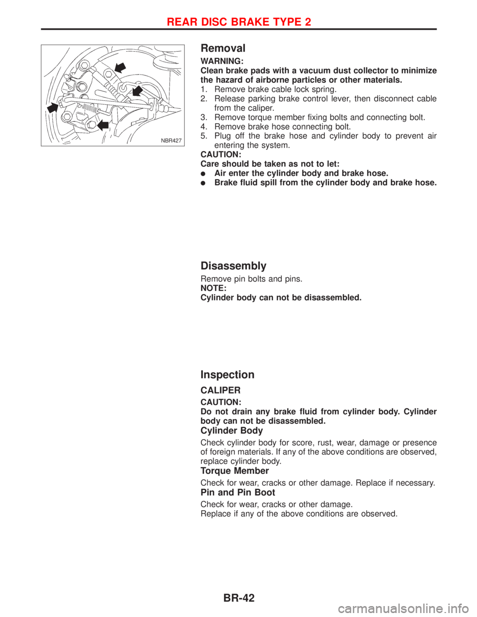
Removal
WARNING:
Clean brake pads with a vacuum dust collector to minimize
the hazard of airborne particles or other materials.
1. Remove brake cable lock spring.
2. Release parking brake control lever, then disconnect cable
from the caliper.
3. Remove torque member fixing bolts and connecting bolt.
4. Remove brake hose connecting bolt.
5. Plug off the brake hose and cylinder body to prevent air
entering the system.
CAUTION:
Care should be taken as not to let:
lAir enter the cylinder body and brake hose.
lBrake fluid spill from the cylinder body and brake hose.
Disassembly
Remove pin bolts and pins.
NOTE:
Cylinder body can not be disassembled.
Inspection
CALIPER
CAUTION:
Do not drain any brake fluid from cylinder body. Cylinder
body can not be disassembled.
Cylinder Body
Check cylinder body for score, rust, wear, damage or presence
of foreign materials. If any of the above conditions are observed,
replace cylinder body.
Torque Member
Check for wear, cracks or other damage. Replace if necessary.
Pin and Pin Boot
Check for wear, cracks or other damage.
Replace if any of the above conditions are observed.
NBR427
REAR DISC BRAKE TYPE 2
BR-42
Page 165 of 2267
ROTOR
Rubbing Surface
Check rotor for roughness, cracks or chips.
Runout
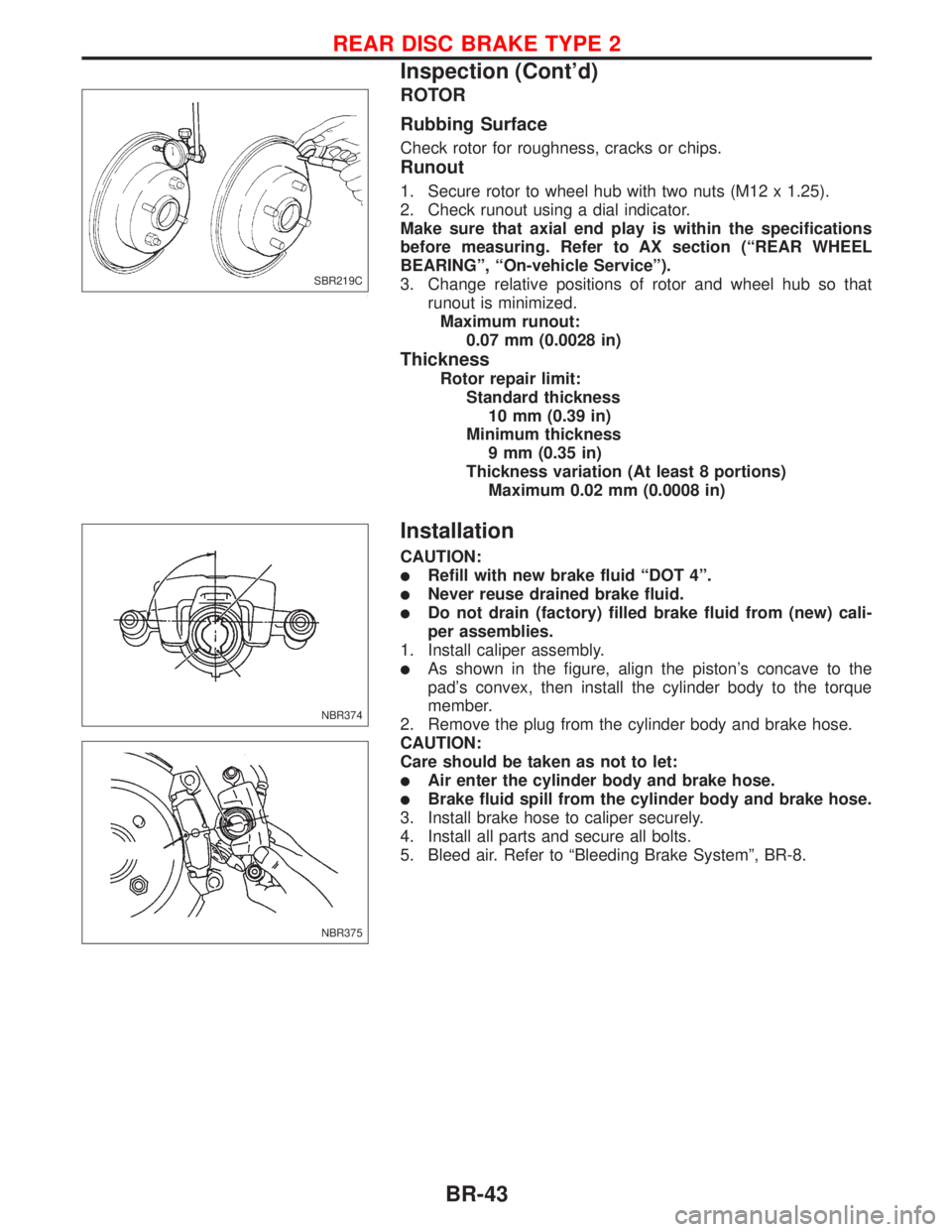
1. Secure rotor to wheel hub with two nuts (M12 x 1.25).
2. Check runout using a dial indicator.
Make sure that axial end play is within the specifications
before measuring. Refer to AX section (ªREAR WHEEL
BEARINGº, ªOn-vehicle Serviceº).
3. Change relative positions of rotor and wheel hub so that
runout is minimized.
Maximum runout:
0.07 mm (0.0028 in)
Thickness
Rotor repair limit:
Standard thickness
10 mm (0.39 in)
Minimum thickness
9 mm (0.35 in)
Thickness variation (At least 8 portions)
Maximum 0.02 mm (0.0008 in)
Installation
CAUTION:
lRefill with new brake fluid ªDOT 4º.
lNever reuse drained brake fluid.
lDo not drain (factory) filled brake fluid from (new) cali-
per assemblies.
1. Install caliper assembly.
lAs shown in the figure, align the piston's concave to the
pad's convex, then install the cylinder body to the torque
member.
2. Remove the plug from the cylinder body and brake hose.
CAUTION:
Care should be taken as not to let:
lAir enter the cylinder body and brake hose.
lBrake fluid spill from the cylinder body and brake hose.
3. Install brake hose to caliper securely.
4. Install all parts and secure all bolts.
5. Bleed air. Refer to ªBleeding Brake Systemº, BR-8.
SBR219C
NBR374
NBR375
REAR DISC BRAKE TYPE 2
Inspection (Cont'd)
BR-43
Page 178 of 2267
1. Disconnect battery cable.
2. Drain brake fluid. Refer to BR-7
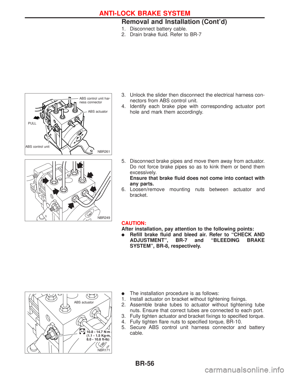
3. Unlock the slider then disconnect the electrical harness con-
nectors from ABS control unit.
4. Identify each brake pipe with corresponding actuator port
hole and mark them accordingly.
5. Disconnect brake pipes and move them away from actuator.
Do not force brake pipes so as to kink them or bend them
excessively.
Ensure that brake fluid does not come into contact with
any parts.
6. Loosen/remove mounting nuts between actuator and
bracket.
CAUTION:
After installation, pay attention to the following points:
lRefill brake fluid and bleed air. Refer to ªCHECK AND
ADJUSTMENTº, BR-7 and ªBLEEDING BRAKE
SYSTEMº, BR-8, respectively.
lThe installation procedure is as follows:
1. Install actuator on bracket without tightening fixings.
2. Assemble brake tubes to actuator without tightening tube
nuts. Ensure that correct tubes are connected to each port.
3. Fully tighten actuator and bracket fixings to specified torque.
4. Fully tighten flare nuts to specified torque, BR-10.
5. Secure ABS control unit harness connector and battery
cable.
NBR261 ABS control unit har-
ness connector
ABS control unitABS actuator
PULL
NBR249
NBR171 ABS actuator
.10.8 - 14.7 N´m
(1.1 - 1.5 Kg-m,
8.0 - 10.8 ft-lb)
ANTI-LOCK BRAKE SYSTEM
Removal and Installation (Cont'd)
BR-56
Page 280 of 2267
Precautions
lRecommended fluid is brake fluid ªDOT 4º.
lDo not reuse drained brake fluid.
lBe careful not to splash brake fluid on painted areas.
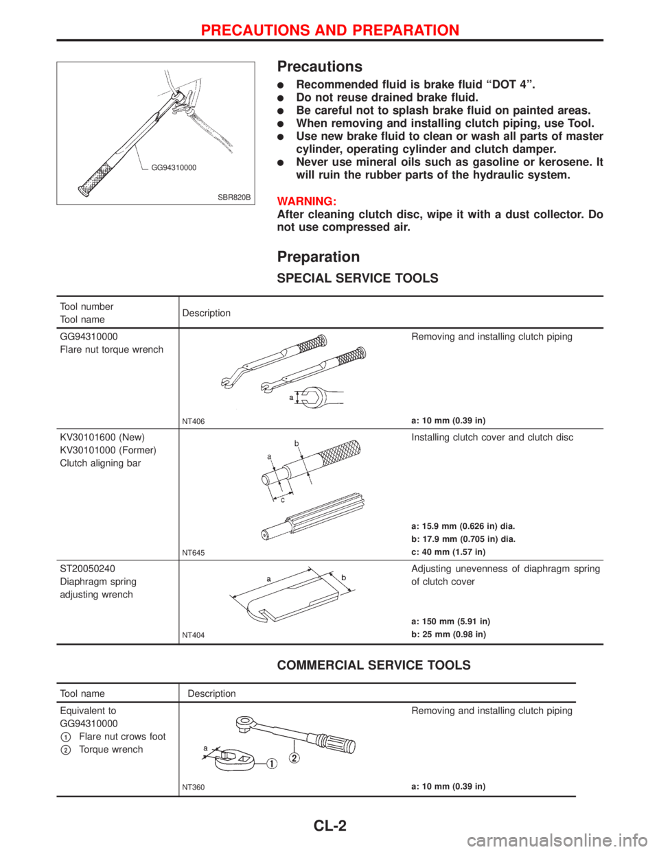
lWhen removing and installing clutch piping, use Tool.
lUse new brake fluid to clean or wash all parts of master
cylinder, operating cylinder and clutch damper.
lNever use mineral oils such as gasoline or kerosene. It
will ruin the rubber parts of the hydraulic system.
WARNING:
After cleaning clutch disc, wipe it with a dust collector. Do
not use compressed air.
Preparation
SPECIAL SERVICE TOOLS
COMMERCIAL SERVICE TOOLS
SBR820B GG94310000
Tool number
Tool nameDescription
GG94310000
Flare nut torque wrench
NT406
Removing and installing clutch piping
a: 10 mm (0.39 in)
KV30101600 (New)
KV30101000 (Former)
Clutch aligning bar
NT645
Installing clutch cover and clutch disc
a: 15.9 mm (0.626 in) dia.
b: 17.9 mm (0.705 in) dia.
c: 40 mm (1.57 in)
ST20050240
Diaphragm spring
adjusting wrench
NT404
Adjusting unevenness of diaphragm spring
of clutch cover
a: 150 mm (5.91 in)
b: 25 mm (0.98 in)
Tool name Description
Equivalent to
GG94310000
p1Flare nut crows foot
p2Torque wrench
NT360
Removing and installing clutch piping
a: 10 mm (0.39 in)
PRECAUTIONS AND PREPARATION
CL-2
Page 292 of 2267
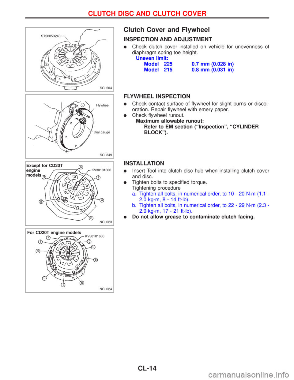
Clutch Cover and Flywheel
INSPECTION AND ADJUSTMENT
lCheck clutch cover installed on vehicle for unevenness of
diaphragm spring toe height.
Uneven limit:
Model 225 0.7 mm (0.028 in)
Model 215 0.8 mm (0.031 in)
FLYWHEEL INSPECTION
lCheck contact surface of flywheel for slight burns or discol-
oration. Repair flywheel with emery paper.
lCheck flywheel runout.
Maximum allowable runout:
Refer to EM section (ªInspectionº, ªCYLINDER
BLOCKº).
INSTALLATION
lInsert Tool into clutch disc hub when installing clutch cover
and disc.
lTighten bolts to specified torque.
Tightening procedure
a. Tighten all bolts, in numerical order, to 10 - 20 N´m (1.1 -
2.0 kg-m,8-14ft-lb).
b. Tighten all bolts, in numerical order, to 22 - 29 N´m (2.3 -
2.9 kg-m, 17 - 21 ft-lb).
lDo not allow grease to contaminate clutch facing.
SCL504
SCL349 Flywheel
Dial gauge
NCL023
Except for CD20T
engine
models6
1 KV30101600
4
2 53
NCL024 KV30101600
For CD20T engine models
1
2
3 45
6 7
8
9
CLUTCH DISC AND CLUTCH COVER
CL-14
Page 419 of 2267
Glow plug
1. Remove glow plug connecting plate.
2. Check each glow plug for continuity.
Continuity should exist:
Approximately 0.5W[at 25ÉC (77ÉF)]
lIf NG, replace glow plug.
3. Install glow plug connecting plate securely.
lDo not bump glow plug heating element. If it is bumped,
replace glow plug with new one. (If glow plug is dropped
from a height of 0.1 m (3.94 in) or greater, replace with
new one.)
lIf glow plug installation hole is contaminated with
carbon, remove using a reamer or suitable tool.
lHand-tighten glow plug by turning it 2 to 3 times, then
tighten using a tool to specified torque.
: 15 - 20 N´m (1.5 - 2.0 kg-m, 11 - 14 ft-lb)
SEF630K Ohmmeter
SEC565B Glow nut
Glow harness
Connecting
plate
Washer
Spring washer
Glow plug
TROUBLE DIAGNOSES 14CD20T
Glow Control System (Cont'd)
EC-125
Page 471 of 2267
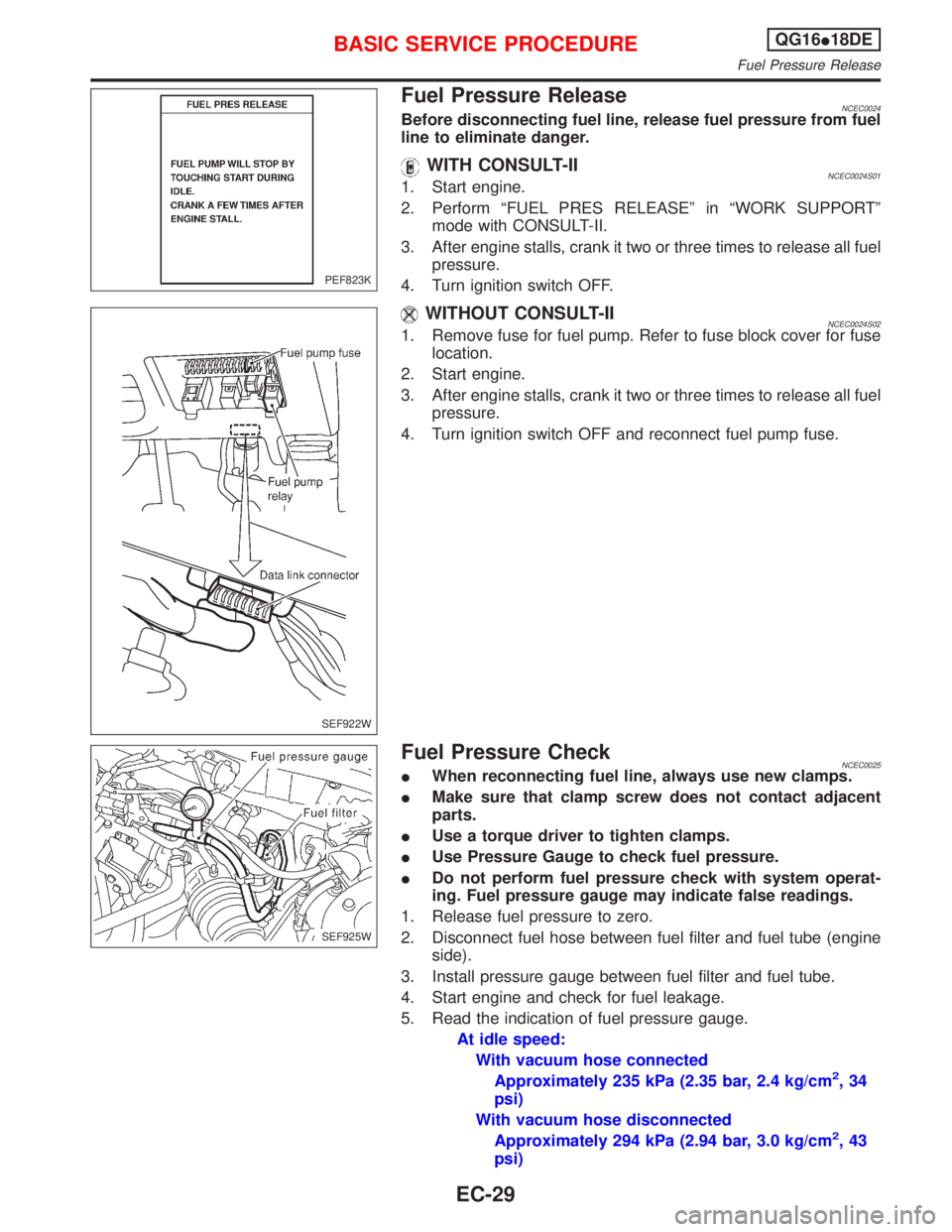
Fuel Pressure ReleaseNCEC0024Before disconnecting fuel line, release fuel pressure from fuel
line to eliminate danger.
WITH CONSULT-IINCEC0024S011. Start engine.
2. Perform ªFUEL PRES RELEASEº in ªWORK SUPPORTº
mode with CONSULT-II.
3. After engine stalls, crank it two or three times to release all fuel
pressure.
4. Turn ignition switch OFF.
WITHOUT CONSULT-IINCEC0024S021. Remove fuse for fuel pump. Refer to fuse block cover for fuse
location.
2. Start engine.
3. After engine stalls, crank it two or three times to release all fuel
pressure.
4. Turn ignition switch OFF and reconnect fuel pump fuse.
Fuel Pressure CheckNCEC0025IWhen reconnecting fuel line, always use new clamps.
IMake sure that clamp screw does not contact adjacent
parts.
IUse a torque driver to tighten clamps.
IUse Pressure Gauge to check fuel pressure.
IDo not perform fuel pressure check with system operat-
ing. Fuel pressure gauge may indicate false readings.
1. Release fuel pressure to zero.
2. Disconnect fuel hose between fuel filter and fuel tube (engine
side).
3. Install pressure gauge between fuel filter and fuel tube.
4. Start engine and check for fuel leakage.
5. Read the indication of fuel pressure gauge.
At idle speed:
With vacuum hose connected
Approximately 235 kPa (2.35 bar, 2.4 kg/cm
2,34
psi)
With vacuum hose disconnected
Approximately 294 kPa (2.94 bar, 3.0 kg/cm
2,43
psi)
PEF823K
SEF922W
SEF925W
BASIC SERVICE PROCEDUREQG16I18DE
Fuel Pressure Release
EC-29
Page 473 of 2267
7. Align protrusions of fuel tubes with those of fuel injectors.
Insert fuel injectors straight into fuel tubes.
8. After properly inserting fuel injectors, check to make sure that
fuel tube protrusions are engaged with those of fuel injectors,
and that flanges of fuel tubes are engaged with clips.
IDiscard old clips; replace with new ones.
9. Tighten fuel tube assembly mounting nuts in numerical
sequence (indicated in the Figure at left) and in two stages.
: Tightening torque N×m (kg-m, ft-lb)
1st stage:
12 - 13 (1.2 - 1.4, 9 - 10)
2nd stage:
17 - 23 (1.7 - 2.4, 13 - 17)
10. Insert fuel hoses into fuel tubes so that ends of fuel hoses butt
up against fuel tubes; fasten with clamps, avoiding bulges.
CAUTION:
After properly connecting fuel tube assembly to injector and
fuel hose, check connection for fuel leakage.
SEF928W
SEF929W
BASIC SERVICE PROCEDUREQG16I18DE
Injector (Cont'd)
EC-31