Page 583 of 2267
ENG SPEED 1,700 - 2,600 rpm
Vehicle speed 64 - 100 km/h (40 - 62 MPH)
B/FUEL SCHDL 3.0 - 5.2 msec
Selector lever Suitable position
If ªTESTINGº is not displayed after 5 minutes, retry from
step 2.
7) Make sure that ªOKº is displayed after touching ªSELF-DIAG
RESULTSº. If ªNGº is displayed, refer to ªDiagnostic
Procedureº, EC-QG-141.
Overall Function CheckNLEC0108Use this procedure to check the overall function of the heated oxy-
gen sensor 1 (front) circuit. During this check, a 1st trip DTC might
not be confirmed.
Without CONSULT-II
1) Start engine and warm it up to normal operating temperature.
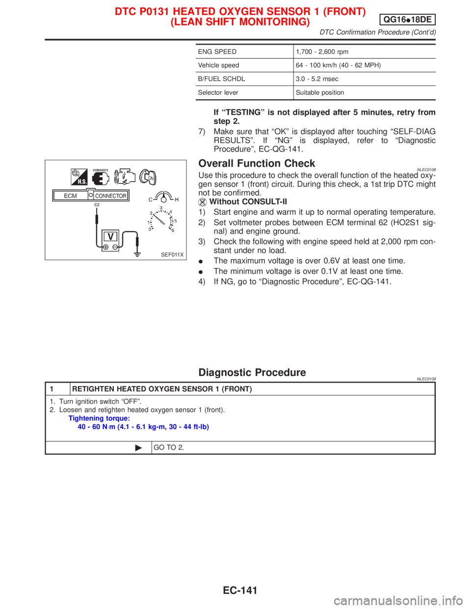
2) Set voltmeter probes between ECM terminal 62 (HO2S1 sig-
nal) and engine ground.
3) Check the following with engine speed held at 2,000 rpm con-
stant under no load.
IThe maximum voltage is over 0.6V at least one time.
IThe minimum voltage is over 0.1V at least one time.
4) If NG, go to ªDiagnostic Procedureº, EC-QG-141.
Diagnostic ProcedureNLEC0109
1 RETIGHTEN HEATED OXYGEN SENSOR 1 (FRONT)
1. Turn ignition switch ªOFFº.
2. Loosen and retighten heated oxygen sensor 1 (front).
Tightening torque:
40-60N×m (4.1 - 6.1 kg-m, 30 - 44 ft-lb)
©GO TO 2.
SEF011X
DTC P0131 HEATED OXYGEN SENSOR 1 (FRONT)
(LEAN SHIFT MONITORING)QG16I18DE
DTC Confirmation Procedure (Cont'd)
EC-141
Page 589 of 2267
If ªTESTINGº is not displayed after 5 minutes, retry from
step 2.
7) Make sure that ªOKº is displayed after touching ªSELF-DIAG
RESULTSº. If ªNGº is displayed, refer to ªDiagnostic
Procedureº, EC-QG-147.
Overall Function CheckNLEC0116Use this procedure to check the overall function of the heated oxy-
gen sensor 1 (front) circuit. During this check, a 1st trip DTC might
not be confirmed.
Without CONSULT-II
1) Start engine and warm it up to normal operating temperature.
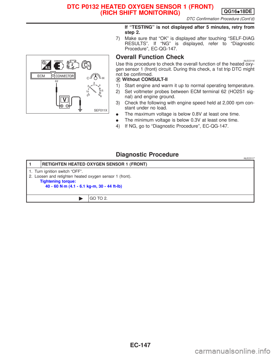
2) Set voltmeter probes between ECM terminal 62 (HO2S1 sig-
nal) and engine ground.
3) Check the following with engine speed held at 2,000 rpm con-
stant under no load.
IThe maximum voltage is below 0.8V at least one time.
IThe minimum voltage is below 0.3V at least one time.
4) If NG, go to ªDiagnostic Procedureº, EC-QG-147.
Diagnostic ProcedureNLEC0117
1 RETIGHTEN HEATED OXYGEN SENSOR 1 (FRONT)
1. Turn ignition switch ªOFFº.
2. Loosen and retighten heated oxygen sensor 1 (front).
Tightening torque:
40-60N×m (4.1 - 6.1 kg-m, 30 - 44 ft-lb)
©GO TO 2.
SEF011X
DTC P0132 HEATED OXYGEN SENSOR 1 (FRONT)
(RICH SHIFT MONITORING)QG16I18DE
DTC Confirmation Procedure (Cont'd)
EC-147
Page 597 of 2267
Diagnostic ProcedureNLEC0126
1 RETIGHTEN GROUND SCREWS
1. Turn ignition switch ªOFFº.
2. Loosen and retighten engine ground screws.
SEF994W
©GO TO 2.
2 RETIGHTEN HEATED OXYGEN SENSOR 1 (FRONT)
Loosen and retighten heated oxygen sensor 1 (front).
Tightening torque:
40-60N×m (4.1 - 6.1 kg-m, 30 - 44 ft-lb)
©GO TO 3.
3 CHECK EXHAUST AIR LEAK
1. Start engine and run it at idle.
2. Listen for an exhaust air leak before three way catalyst.
SEF099P
OK or NG
OK©GO TO 4.
NG©Repair or replace.
4 CHECK FOR INTAKE AIR LEAK
Listen for an intake air leak after the mass air flow sensor.
OK or NG
OK©GO TO 5.
NG©Repair or replace.
DTC P0133 HEATED OXYGEN SENSOR 1 (FRONT)
(RESPONSE MONITORING)QG16I18DE
Diagnostic Procedure
EC-155
Page 605 of 2267
Diagnostic ProcedureNLEC0134
1 RETIGHTEN HEATED OXYGEN SENSOR 1 (FRONT)
Loosen and retighten heated oxygen sensor 1 (front).
Tightening torque:
40-60N×m (4.1 - 6.1 kg-m, 30 - 44 ft-lb)
©GO TO 2.
2 CHECK INPUT SIGNAL CIRCUIT
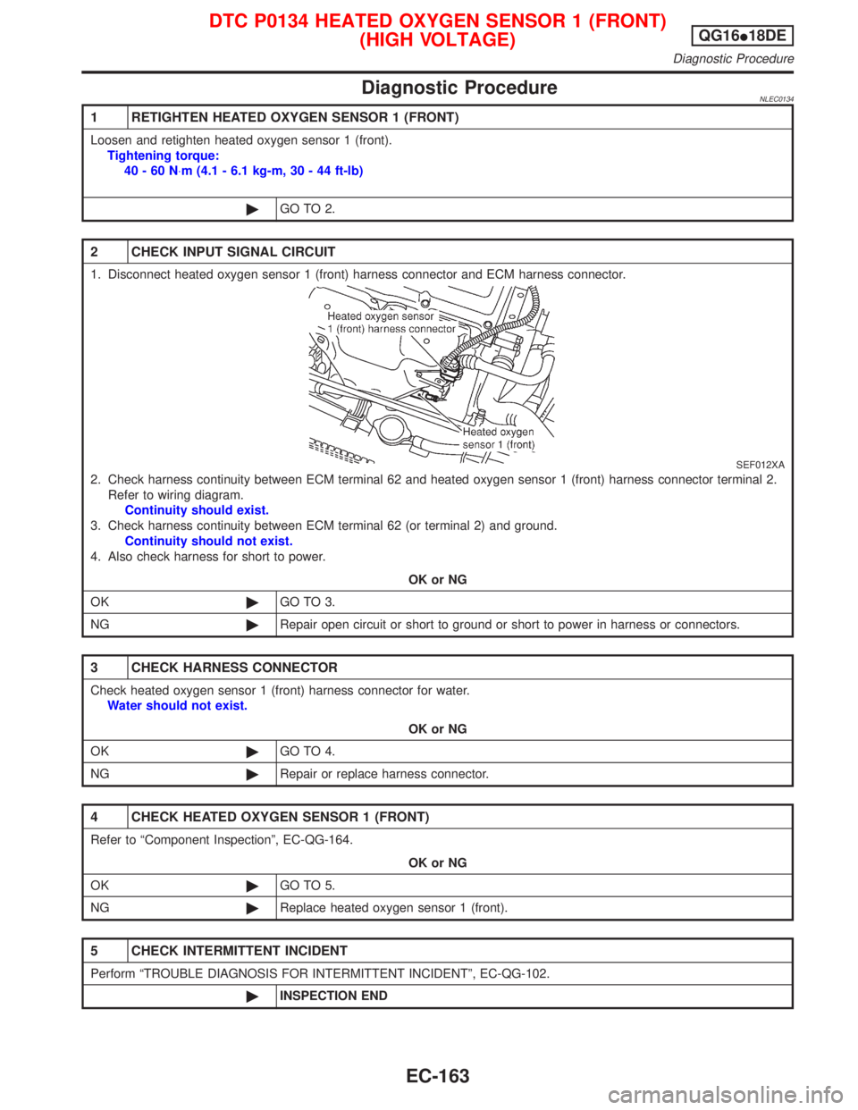
1. Disconnect heated oxygen sensor 1 (front) harness connector and ECM harness connector.
SEF012XA
2. Check harness continuity between ECM terminal 62 and heated oxygen sensor 1 (front) harness connector terminal 2.
Refer to wiring diagram.
Continuity should exist.
3. Check harness continuity between ECM terminal 62 (or terminal 2) and ground.
Continuity should not exist.
4. Also check harness for short to power.
OK or NG
OK©GO TO 3.
NG©Repair open circuit or short to ground or short to power in harness or connectors.
3 CHECK HARNESS CONNECTOR
Check heated oxygen sensor 1 (front) harness connector for water.
Water should not exist.
OK or NG
OK©GO TO 4.
NG©Repair or replace harness connector.
4 CHECK HEATED OXYGEN SENSOR 1 (FRONT)
Refer to ªComponent Inspectionº, EC-QG-164.
OK or NG
OK©GO TO 5.
NG©Replace heated oxygen sensor 1 (front).
5 CHECK INTERMITTENT INCIDENT
Perform ªTROUBLE DIAGNOSIS FOR INTERMITTENT INCIDENTº, EC-QG-102.
©INSPECTION END
DTC P0134 HEATED OXYGEN SENSOR 1 (FRONT)
(HIGH VOLTAGE)QG16I18DE
Diagnostic Procedure
EC-163
Page 831 of 2267
Fuel Pressure ReleaseNCEC0024Before disconnecting fuel line, release fuel pressure from fuel
line to eliminate danger.
WITH CONSULT-IINCEC0024S011. Start engine.
2. Perform ªFUEL PRES RELEASEº in ªWORK SUPPORTº
mode with CONSULT-II.
3. After engine stalls, crank it two or three times to release all fuel
pressure.
4. Turn ignition switch OFF.
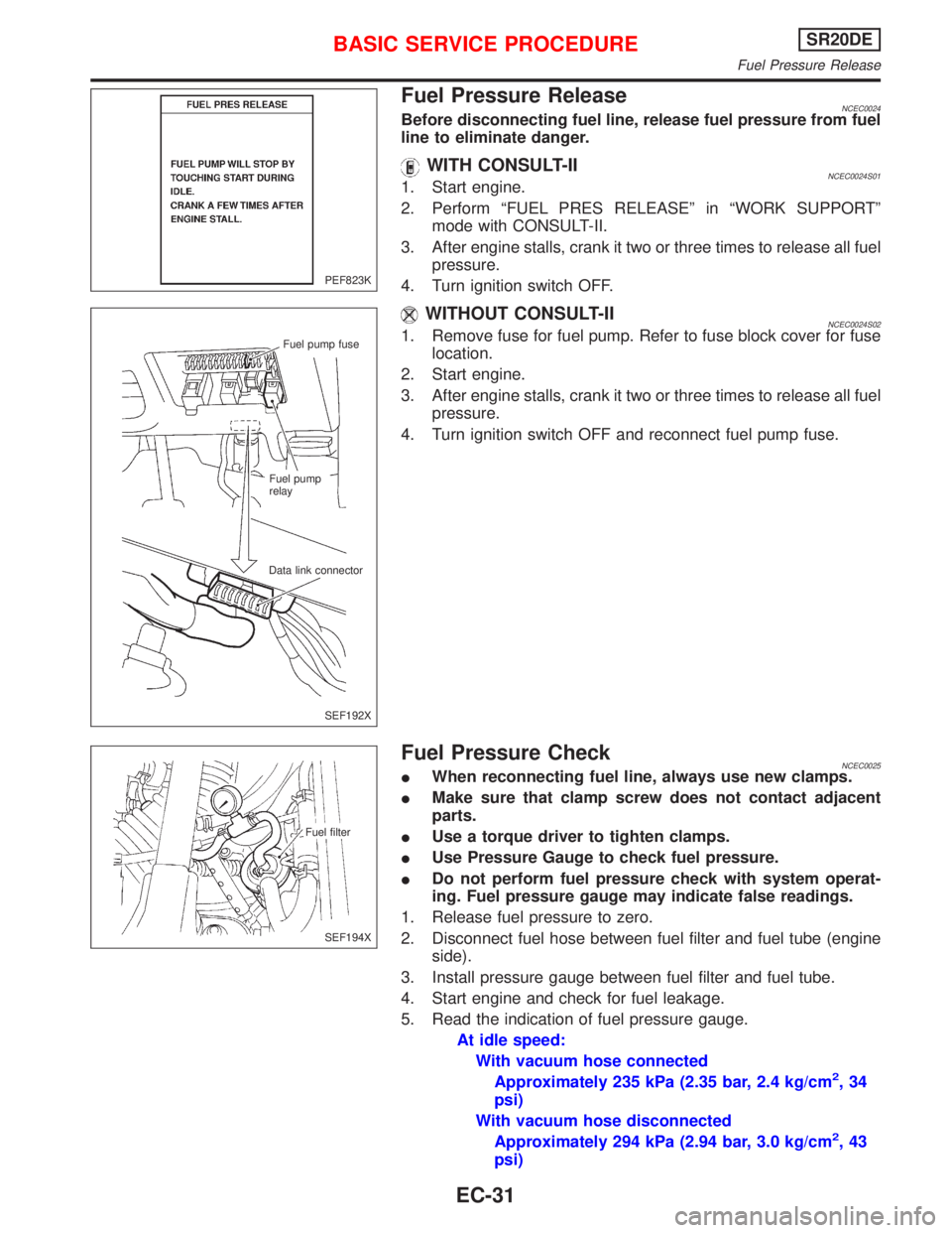
WITHOUT CONSULT-IINCEC0024S021. Remove fuse for fuel pump. Refer to fuse block cover for fuse
location.
2. Start engine.
3. After engine stalls, crank it two or three times to release all fuel
pressure.
4. Turn ignition switch OFF and reconnect fuel pump fuse.
Fuel Pressure CheckNCEC0025IWhen reconnecting fuel line, always use new clamps.
IMake sure that clamp screw does not contact adjacent
parts.
IUse a torque driver to tighten clamps.
IUse Pressure Gauge to check fuel pressure.
IDo not perform fuel pressure check with system operat-
ing. Fuel pressure gauge may indicate false readings.
1. Release fuel pressure to zero.
2. Disconnect fuel hose between fuel filter and fuel tube (engine
side).
3. Install pressure gauge between fuel filter and fuel tube.
4. Start engine and check for fuel leakage.
5. Read the indication of fuel pressure gauge.
At idle speed:
With vacuum hose connected
Approximately 235 kPa (2.35 bar, 2.4 kg/cm
2,34
psi)
With vacuum hose disconnected
Approximately 294 kPa (2.94 bar, 3.0 kg/cm
2,43
psi)
PEF823K
Fuel pump fuse
Fuel pump
relay
Data link connector
SEF192X
Fuel filter
SEF194X
BASIC SERVICE PROCEDURESR20DE
Fuel Pressure Release
EC-31
Page 833 of 2267
IDiscard old clips; replace with new ones.
10. Install injectors with fuel tube assembly to intake manifold.
IPay extra care to prevent O-rings from being scratched by
sharp edges.
IApply a coat of new engine oil to O-rings before installa-
tion.
11. Tighten fuel tube assembly mounting bolts in numerical
sequence (indicated in the Figure at left) and in two stages.
: Tightening torque N×m (kg-m, ft-lb)
1st stage:
9.4 - 10.7 (0.95 - 1.10, 83 - 95)
2nd stage:
21 - 26 (2.1 - 2.7, 16 - 19)
12. Insert fuel hoses into fuel tubes so that ends of fuel hoses butt
up against fuel tubes; fasten with clamps, avoiding bulges.
ILubricate fuel hoses with a smear of silicone oil.
13. Reinstall any parts removed in reverse order of removal.
CAUTION:
After properly connecting fuel hose to injector and fuel tube
assembly, check connection for fuel leakage.
Fuel tube
O-ring
Spacer
Clip
Injector
Apply engine oil.
SEF195X
SEF196X
BASIC SERVICE PROCEDURESR20DE
Injector (Cont'd)
EC-33
Page 953 of 2267
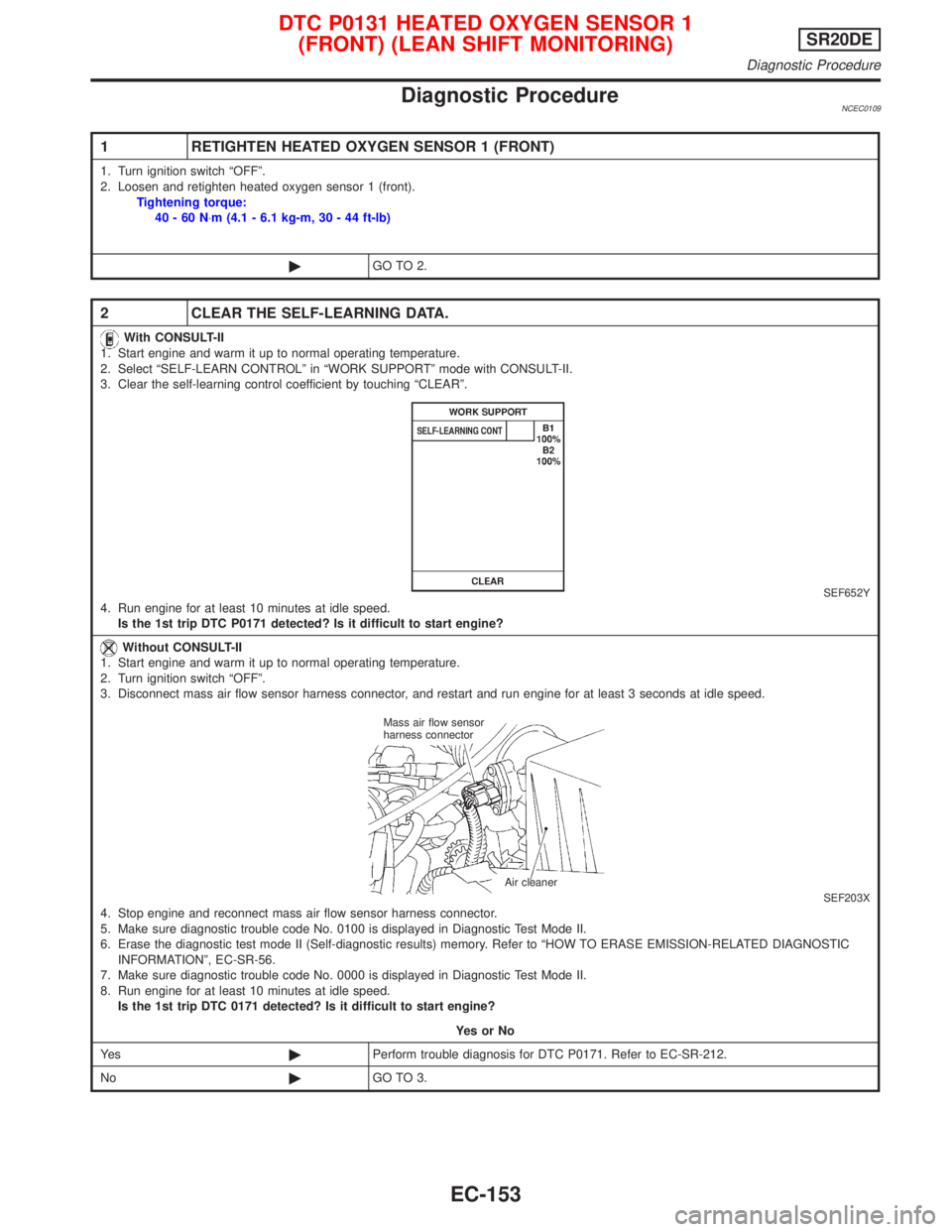
Diagnostic ProcedureNCEC0109
1 RETIGHTEN HEATED OXYGEN SENSOR 1 (FRONT)
1. Turn ignition switch ªOFFº.
2. Loosen and retighten heated oxygen sensor 1 (front).
Tightening torque:
40-60N×m (4.1 - 6.1 kg-m, 30 - 44 ft-lb)
©GO TO 2.
2 CLEAR THE SELF-LEARNING DATA.
With CONSULT-II
1. Start engine and warm it up to normal operating temperature.
2. Select ªSELF-LEARN CONTROLº in ªWORK SUPPORTº mode with CONSULT-II.
3. Clear the self-learning control coefficient by touching ªCLEARº.
SEF652Y4. Run engine for at least 10 minutes at idle speed.
Is the 1st trip DTC P0171 detected? Is it difficult to start engine?
Without CONSULT-II
1. Start engine and warm it up to normal operating temperature.
2. Turn ignition switch ªOFFº.
3. Disconnect mass air flow sensor harness connector, and restart and run engine for at least 3 seconds at idle speed.
SEF203X4. Stop engine and reconnect mass air flow sensor harness connector.
5. Make sure diagnostic trouble code No. 0100 is displayed in Diagnostic Test Mode II.
6. Erase the diagnostic test mode II (Self-diagnostic results) memory. Refer to ªHOW TO ERASE EMISSION-RELATED DIAGNOSTIC
INFORMATIONº, EC-SR-56.
7. Make sure diagnostic trouble code No. 0000 is displayed in Diagnostic Test Mode II.
8. Run engine for at least 10 minutes at idle speed.
Is the 1st trip DTC 0171 detected? Is it difficult to start engine?
YesorNo
Ye s©Perform trouble diagnosis for DTC P0171. Refer to EC-SR-212.
No©GO TO 3.
Mass air flow sensor
harness connector
Air cleaner
DTC P0131 HEATED OXYGEN SENSOR 1
(FRONT) (LEAN SHIFT MONITORING)SR20DE
Diagnostic Procedure
EC-153
Page 959 of 2267
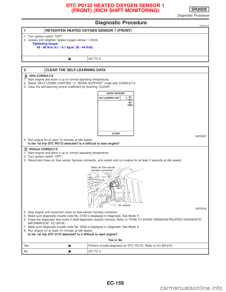
Diagnostic Procedure=NCEC0117
1 RETIGHTEN HEATED OXYGEN SENSOR 1 (FRONT)
1. Turn ignition switch ªOFFº.
2. Loosen and retighten heated oxygen sensor 1 (front).
Tightening torque:
40-60N×m (4.1 - 6.1 kg-m, 30 - 44 ft-lb)
©GO TO 2.
2 CLEAR THE SELF-LEARNING DATA
With CONSULT-II
1. Start engine and warm it up to normal operating temperature.
2. Select ªSELF-LEARN CONTROLº in ªWORK SUPPORTº mode with CONSULT-II.
3. Clear the self-learning control coefficient by touching ªCLEARº.
SEF652Y4. Run engine for at least 10 minutes at idle speed.
Is the 1st trip DTC P0172 detected? Is it difficult to start engine?
Without CONSULT-II
1. Start engine and warm it up to normal operating temperature.
2. Turn ignition switch ªOFFº.
3. Disconnect mass air flow sensor harness connector, and restart and run engine for at least 3 seconds at idle speed.
SEF203X4. Stop engine and reconnect mass air flow sensor harness connector.
5. Make sure diagnostic trouble code No. 0100 is displayed in Diagnostic Test Mode II.
6. Erase the diagnostic test mode II (Self-diagnostic results) memory. Refer to ªHOW TO ERASE EMISSION-RELATED DIAGNOSTIC
INFORMATIONº, EC-SR-56.
7. Make sure diagnostic trouble code No. 0000 is displayed in Diagnostic Test Mode II.
8. Run engine for at least 10 minutes at idle speed.
Is the 1st trip DTC 0172 detected? Is it difficult to start engine?
YesorNo
Ye s©Perform trouble diagnosis for DTC P0172. Refer to EC-SR-218.
No©GO TO 3.
Mass air flow sensor
harness connector
Air cleaner
DTC P0132 HEATED OXYGEN SENSOR 1
(FRONT) (RICH SHIFT MONITORING)SR20DE
Diagnostic Procedure
EC-159