Page 33 of 2267
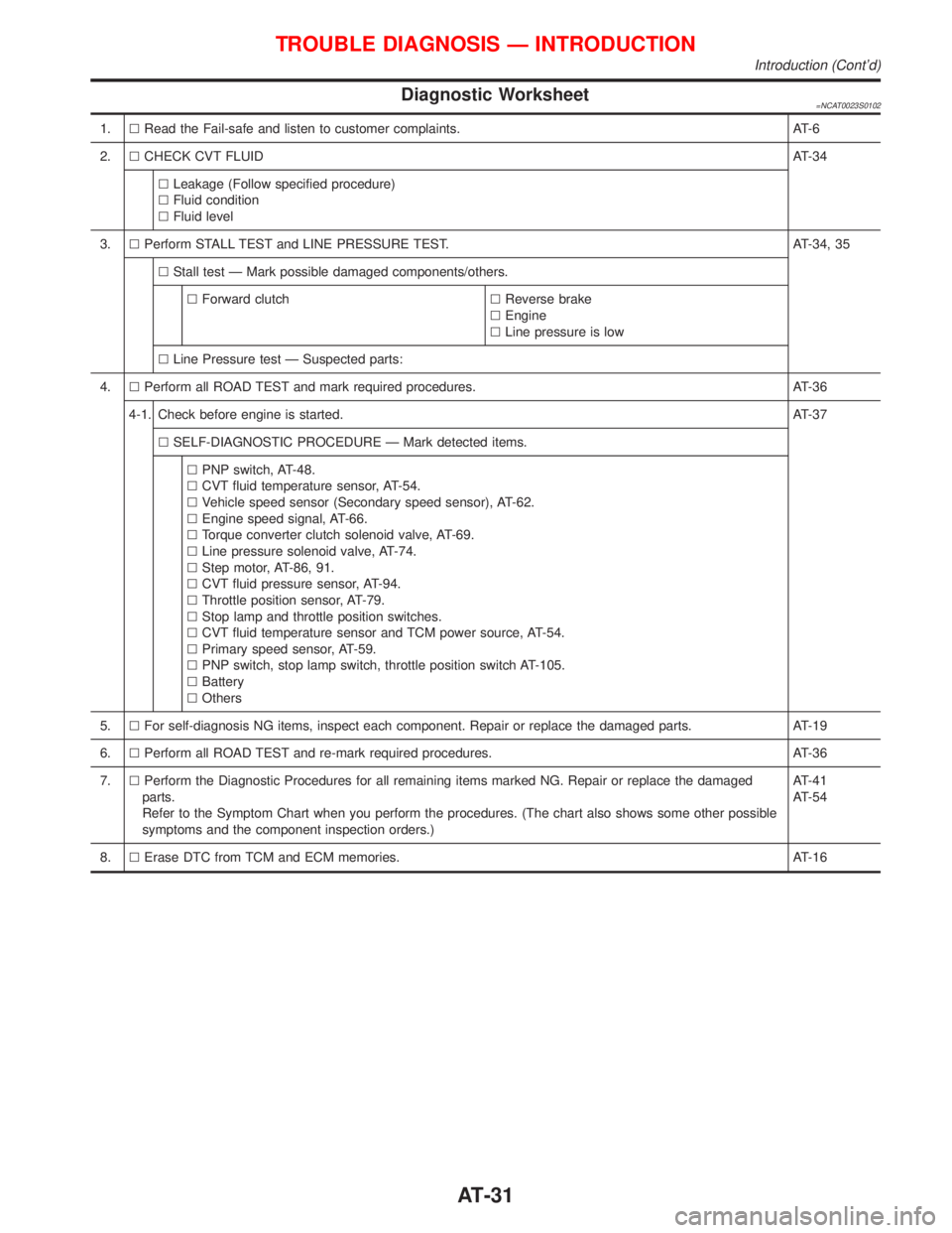
Diagnostic Worksheet=NCAT0023S0102
1.lRead the Fail-safe and listen to customer complaints. AT-6
2.lCHECK CVT FLUIDAT-34
lLeakage (Follow specified procedure)
lFluid condition
lFluid level
3.lPerform STALL TEST and LINE PRESSURE TEST. AT-34, 35
lStall test Ð Mark possible damaged components/others.
lForward clutchlReverse brake
lEngine
lLine pressure is low
lLine Pressure test Ð Suspected parts:
4.lPerform all ROAD TEST and mark required procedures. AT-36
4-1. Check before engine is started.AT-37
lSELF-DIAGNOSTIC PROCEDURE Ð Mark detected items.
lPNP switch, AT-48.
lCVT fluid temperature sensor, AT-54.
lVehicle speed sensor (Secondary speed sensor), AT-62.
lEngine speed signal, AT-66.
lTorque converter clutch solenoid valve, AT-69.
lLine pressure solenoid valve, AT-74.
lStep motor, AT-86, 91.
lCVT fluid pressure sensor, AT-94.
lThrottle position sensor, AT-79.
lStop lamp and throttle position switches.
lCVT fluid temperature sensor and TCM power source, AT-54.
lPrimary speed sensor, AT-59.
lPNP switch, stop lamp switch, throttle position switch AT-105.
lBattery
lOthers
5.lFor self-diagnosis NG items, inspect each component. Repair or replace the damaged parts. AT-19
6.lPerform all ROAD TEST and re-mark required procedures. AT-36
7.lPerform the Diagnostic Procedures for all remaining items marked NG. Repair or replace the damaged
parts.
Refer to the Symptom Chart when you perform the procedures. (The chart also shows some other possible
symptoms and the component inspection orders.)AT-41
AT-54
8.lErase DTC from TCM and ECM memories. AT-16
TROUBLE DIAGNOSIS Ð INTRODUCTION
Introduction (Cont'd)
AT-31
Page 43 of 2267
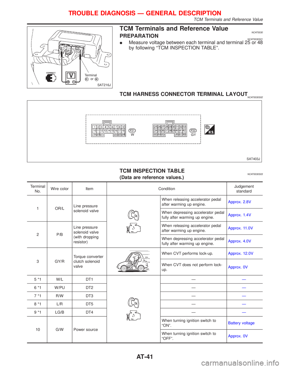
TCM Terminals and Reference ValueNCAT0030PREPARATIONNCAT0030S01IMeasure voltage between each terminal and terminal 25 or 48
by following ªTCM INSPECTION TABLEº.
TCM HARNESS CONNECTOR TERMINAL LAYOUTNCAT0030S02
TCM INSPECTION TABLENCAT0030S03(Data are reference values.)
Terminal
No.Wire color Item ConditionJudgement
standard
1 OR/LLine pressure
solenoid valve
When releasing accelerator pedal
after warming up engine.Approx. 2.8V
When depressing accelerator pedal
fully after warming up engine.Approx. 1.4V
2 P/BLine pressure
solenoid valve
(with dropping
resistor)When releasing accelerator pedal
after warming up engine.Approx. 11.0V
When depressing accelerator pedal
fully after warming up engine.Approx. 4.0V
3 GY/RTorque converter
clutch solenoid
valve
When CVT performs lock-up.Approx. 12.0V
When CVT does not perform lock-
up.Approx. 0V
5 *1 W/L DT1
ÐÐ
6 *1 W/PU DT2 ÐÐ
7 *1 R/W DT3 ÐÐ
8 *1 L/R DT5 ÐÐ
9 *1 LG/B DT4 ÐÐ
10 G/W Power sourceWhen turning ignition switch to
ªONº.Battery voltage
When turning ignition switch to
ªOFFº.Approx. 0V
SAT216J Terminal
p25orp48
SAT403J
TROUBLE DIAGNOSIS Ð GENERAL DESCRIPTION
TCM Terminals and Reference Value
AT-41
Page 71 of 2267
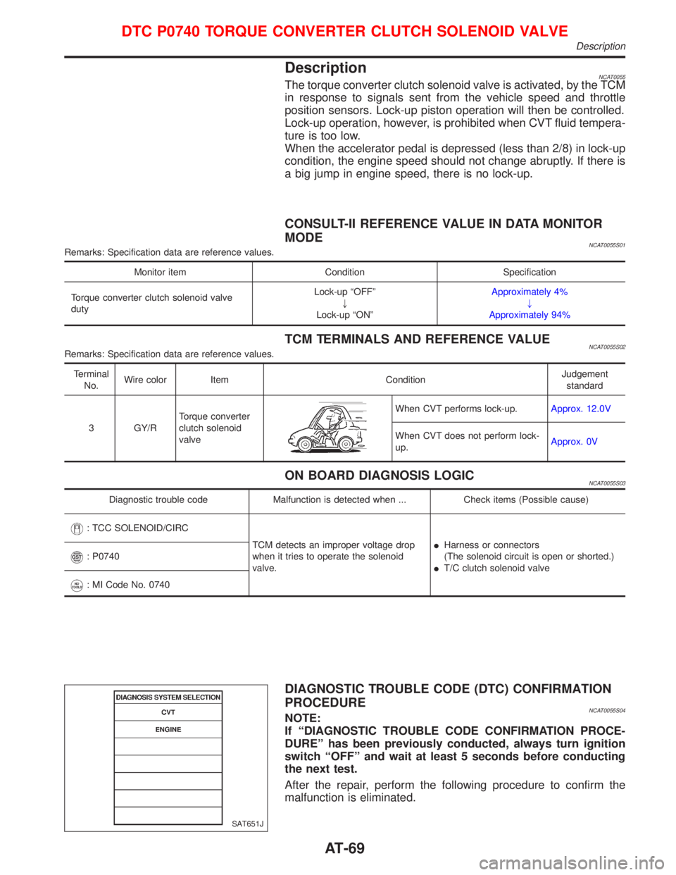
DescriptionNCAT0055The torque converter clutch solenoid valve is activated, by the TCM
in response to signals sent from the vehicle speed and throttle
position sensors. Lock-up piston operation will then be controlled.
Lock-up operation, however, is prohibited when CVT fluid tempera-
ture is too low.
When the accelerator pedal is depressed (less than 2/8) in lock-up
condition, the engine speed should not change abruptly. If there is
a big jump in engine speed, there is no lock-up.
CONSULT-II REFERENCE VALUE IN DATA MONITOR
MODE
NCAT0055S01Remarks: Specification data are reference values.
Monitor item Condition Specification
Torque converter clutch solenoid valve
dutyLock-up ªOFFº
"
Lock-up ªONºApproximately 4%
"
Approximately 94%
TCM TERMINALS AND REFERENCE VALUENCAT0055S02Remarks: Specification data are reference values.
Terminal
No.Wire color Item ConditionJudgement
standard
3 GY/RTorque converter
clutch solenoid
valve
When CVT performs lock-up.Approx. 12.0V
When CVT does not perform lock-
up.Approx. 0V
ON BOARD DIAGNOSIS LOGICNCAT0055S03
Diagnostic trouble code Malfunction is detected when ... Check items (Possible cause)
: TCC SOLENOID/CIRC
TCM detects an improper voltage drop
when it tries to operate the solenoid
valve.IHarness or connectors
(The solenoid circuit is open or shorted.)
IT/C clutch solenoid valve
: P0740
: MI Code No. 0740
DIAGNOSTIC TROUBLE CODE (DTC) CONFIRMATION
PROCEDURE
NCAT0055S04NOTE:
If ªDIAGNOSTIC TROUBLE CODE CONFIRMATION PROCE-
DUREº has been previously conducted, always turn ignition
switch ªOFFº and wait at least 5 seconds before conducting
the next test.
After the repair, perform the following procedure to confirm the
malfunction is eliminated.
SAT651J
DTC P0740 TORQUE CONVERTER CLUTCH SOLENOID VALVE
Description
AT-69
Page 72 of 2267
With CONSULT-II
1) Turn ignition switch ªONº.
2) Select ªDATA MONITORº mode for ªENGINEº with CON-
SULT-II and wait at least 10 seconds.
If the check result is ªNGº, go to ªDiagnostic Procedureº,
AT-72.
With GST
Follow the procedure ªWith CONSULT-IIº.
SAT654J
DTC P0740 TORQUE CONVERTER CLUTCH SOLENOID VALVE
Description (Cont'd)
AT-70
Page 73 of 2267
Wiring Diagram Ð AT Ð TCVNCAT0207
M48
GY/R GY/RF102
GY/R
M48
F71
AT-TCV-01
M53
5
15 16 17 1918620414313212721822923W 3
21LU
DUTY SOL
9
11110
24
W
3 2 1 45678
910 11 12 13 14 15 16 17 18
19 20 21 22 23 24
F71 GY/R
F10254
96 2
7 3
81
G10
YAT149
TCM
(TRANSMISSION
CONTROL
MODULE)
: Detectable line for DTC
: Non-detectable line for DTC
CONTROL VALVE
(TORQUE
CONVERTER
CLUTCH
SOLENOID VALVE)
DTC P0740 TORQUE CONVERTER CLUTCH SOLENOID VALVE
Wiring Diagram Ð AT Ð TCV
AT-71
Page 74 of 2267
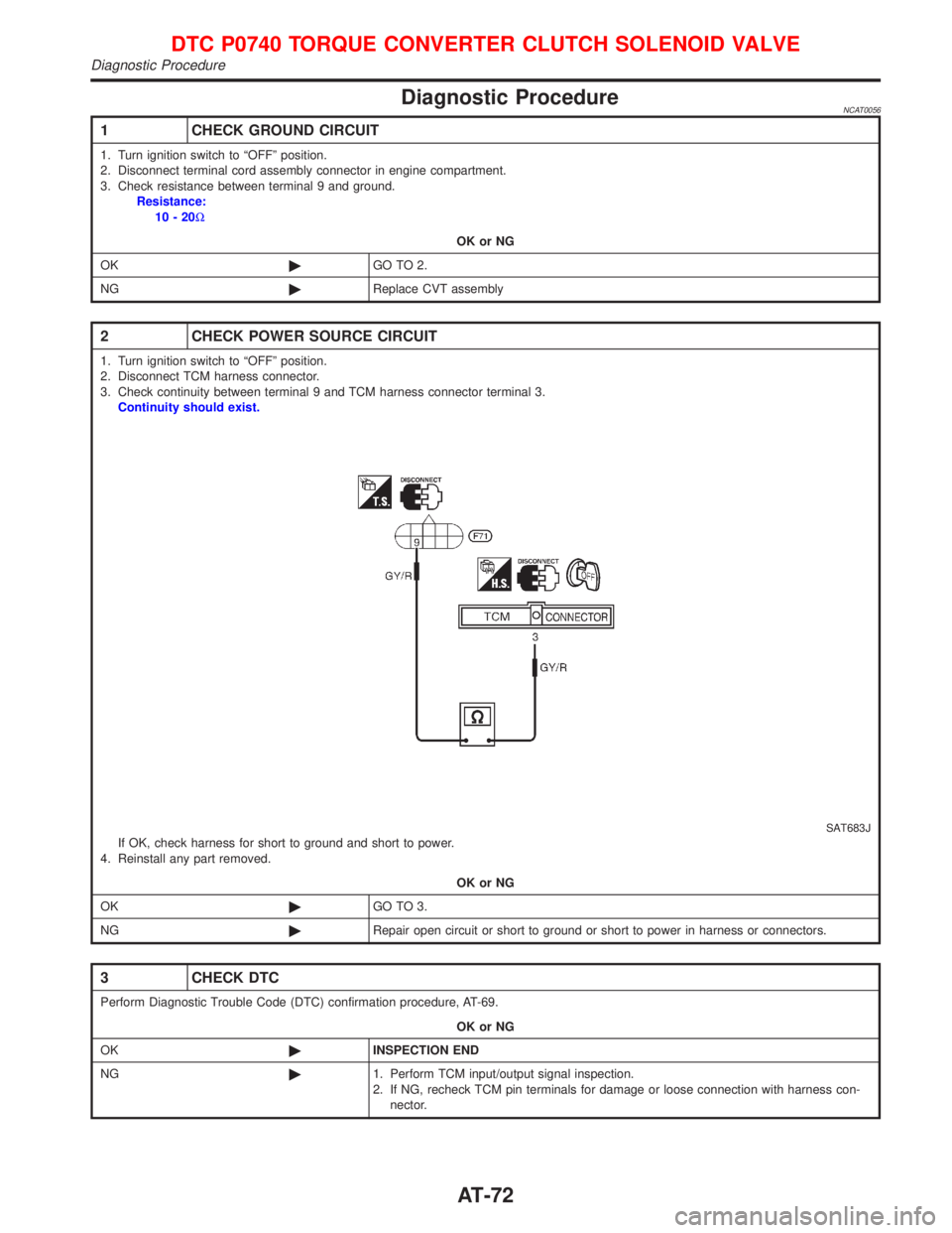
Diagnostic ProcedureNCAT0056
1 CHECK GROUND CIRCUIT
1. Turn ignition switch to ªOFFº position.
2. Disconnect terminal cord assembly connector in engine compartment.
3. Check resistance between terminal 9 and ground.
Resistance:
10-20W
OK or NG
OK©GO TO 2.
NG©Replace CVT assembly
2 CHECK POWER SOURCE CIRCUIT
1. Turn ignition switch to ªOFFº position.
2. Disconnect TCM harness connector.
3. Check continuity between terminal 9 and TCM harness connector terminal 3.
Continuity should exist.
SAT683JIf OK, check harness for short to ground and short to power.
4. Reinstall any part removed.
OK or NG
OK©GO TO 3.
NG©Repair open circuit or short to ground or short to power in harness or connectors.
3 CHECK DTC
Perform Diagnostic Trouble Code (DTC) confirmation procedure, AT-69.
OK or NG
OK©INSPECTION END
NG©1. Perform TCM input/output signal inspection.
2. If NG, recheck TCM pin terminals for damage or loose connection with harness con-
nector.
DTC P0740 TORQUE CONVERTER CLUTCH SOLENOID VALVE
Diagnostic Procedure
AT-72
Page 75 of 2267
Component InspectionNCAT0057TORQUE CONVERTER CLUTCH SOLENOID VALVENCAT0057S01IFor removal, refer to AT-116.
Resistance CheckNCAT0057S0101ICheck resistance between two terminals.
Solenoid valve Terminal No.Resistance
(Approx.)
Torque converter
clutch solenoid
valve9Ground of TCC
solenoid valve10-16W
Operation CheckNCAT0057S0102ICheck solenoid valve by listening for its operating sound while
applying battery voltage to the terminal and ground of TCC
solenoid valve.
SAT684J To torque converter clutch solenoid valve
SAT685J To torque converter clutch solenoid valve
DTC P0740 TORQUE CONVERTER CLUTCH SOLENOID VALVE
Component Inspection
AT-73
Page 118 of 2267
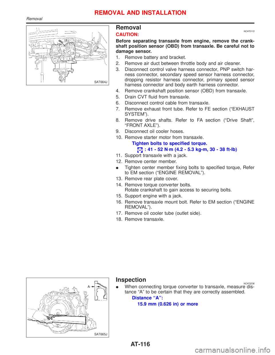
RemovalNCAT0115CAUTION:
Before separating transaxle from engine, remove the crank-
shaft position sensor (OBD) from transaxle. Be careful not to
damage sensor.
1. Remove battery and bracket.
2. Remove air duct between throttle body and air cleaner.
3. Disconnect control valve harness connector, PNP switch har-
ness connector, secondary speed sensor harness connector,
dropping resistor harness connector, primary speed sensor
harness connector and body earth harness connector.
4. Remove crankshaft position sensor (OBD) from transaxle.
5. Drain CVT fluid from transaxle.
6. Disconnect control cable from transaxle.
7. Remove exhaust front tube. Refer to FE section (ªEXHAUST
SYSTEMº).
8. Remove drive shafts. Refer to FA section (ªDrive Shaftº,
ªFRONT AXLEº).
9. Disconnect oil cooler hoses.
10. Remove starter motor from transaxle.
Tighten bolts to specified torque.
:41-52N×m (4.2 - 5.3 kg-m, 30 - 38 ft-lb)
11. Support transaxle with a jack.
12. Remove center member.
ITighten center member fixing bolts to specified torque, Refer
to EM section (ªENGINE REMOVALº).
13. Remove rear plate cover.
14. Remove torque converter bolts.
Rotate crankshaft to gain access to securing bolts.
15. Support engine with a jack.
16. Remove transaxle mount bolt. Refer to EM section (ªENGINE
REMOVALº).
17. Remove oil cooler tube (outlet side).
18. Remove transaxle.
InspectionNCAT0236IWhen connecting torque converter to transaxle, measure dis-
tance ªAº to be certain that they are correctly assembled.
Distance ªAº:
15.9 mm (0.626 in) or more
SAT664J
SAT665J
REMOVAL AND INSTALLATION
Removal
AT-116