Page 1575 of 2267
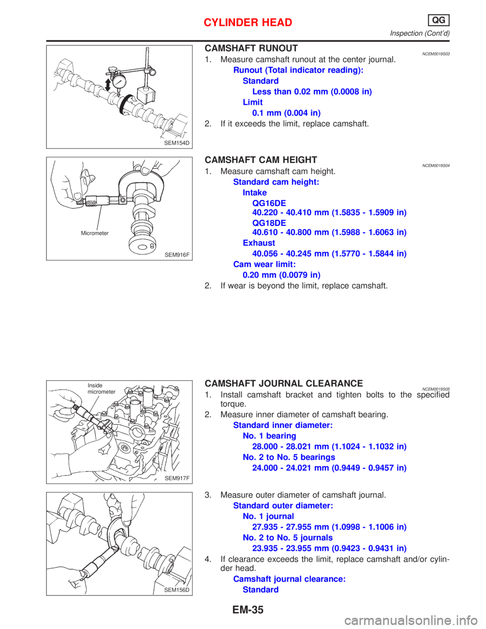
CAMSHAFT RUNOUTNCEM0019S031. Measure camshaft runout at the center journal.
Runout (Total indicator reading):
Standard
Less than 0.02 mm (0.0008 in)
Limit
0.1 mm (0.004 in)
2. If it exceeds the limit, replace camshaft.
CAMSHAFT CAM HEIGHTNCEM0019S041. Measure camshaft cam height.
Standard cam height:
Intake
QG16DE
40.220 - 40.410 mm (1.5835 - 1.5909 in)
QG18DE
40.610 - 40.800 mm (1.5988 - 1.6063 in)
Exhaust
40.056 - 40.245 mm (1.5770 - 1.5844 in)
Cam wear limit:
0.20 mm (0.0079 in)
2. If wear is beyond the limit, replace camshaft.
CAMSHAFT JOURNAL CLEARANCENCEM0019S051. Install camshaft bracket and tighten bolts to the specified
torque.
2. Measure inner diameter of camshaft bearing.
Standard inner diameter:
No. 1 bearing
28.000 - 28.021 mm (1.1024 - 1.1032 in)
No. 2 to No. 5 bearings
24.000 - 24.021 mm (0.9449 - 0.9457 in)
3. Measure outer diameter of camshaft journal.
Standard outer diameter:
No. 1 journal
27.935 - 27.955 mm (1.0998 - 1.1006 in)
No. 2 to No. 5 journals
23.935 - 23.955 mm (0.9423 - 0.9431 in)
4. If clearance exceeds the limit, replace camshaft and/or cylin-
der head.
Camshaft journal clearance:
Standard
SEM154D
SEM916F Micrometer
SEM917F Inside
micrometer
SEM156D
CYLINDER HEADQG
Inspection (Cont'd)
EM-35
Page 1584 of 2267
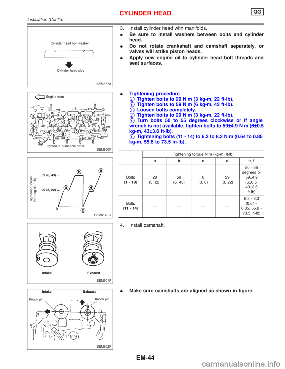
3. Install cylinder head with manifolds.
IBe sure to install washers between bolts and cylinder
head.
IDo not rotate crankshaft and camshaft separately, or
valves will strike piston heads.
IApply new engine oil to cylinder head bolt threads and
seat surfaces.
ITightening procedure
paTighten bolts to 29 N×m (3 kg-m, 22 ft-lb).
pbTighten bolts to 59 N×m (6 kg-m, 43 ft-lb).
pcLoosen bolts completely.
pdTighten bolts to 29 N×m (3 kg-m, 22 ft-lb).
peTurn bolts 50 to 55 degrees clockwise or if angle
wrench is not available, tighten bolts to 59 4.9 N×m (6 0.5
kg-m, 43 3.6 ft-lb).
pfTightening bolts (11 - 14) to 6.3 to 8.3 N×m (0.64 to 0.85
kg-m, 55.8 to 73.5 in-lb).
Tightening torque N×m (kg-m, ft-lb)
abcde,f
Bolts
(1-10)29
(3, 22)59
(6, 43)0
(0, 0)29
(3, 22)50-55
degrees or
59 4.9
(6 0.5,
43 3.6
ft-lb)
Bolts
(11-14)ÐÐÐÐ6.3 - 8.3
(0.64 -
0.85, 55.8 -
73.5 in-lb)
4. Install camshaft.
IMake sure camshafts are aligned as shown in figure.
SEM877A Cylinder head bolt washer
Cylinder head side
SEM900F Engine front
Tighten in numerical order.
SEM614EC
Tightening torque
N´m (kg-m, ft-lb)
59 (6, 43)
29 (3, 22)
SEM901F Intake Exhaust
SEM902F Intake Exhaust
Knock pin
Knock pin
CYLINDER HEADQG
Installation (Cont'd)
EM-44
Page 1585 of 2267
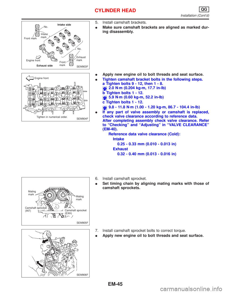
5. Install camshaft brackets.
IMake sure camshaft brackets are aligned as marked dur-
ing disassembly.
IApply new engine oil to bolt threads and seat surface.
ITighten camshaft bracket bolts in the following steps.
a Tighten bolts9-12,then1-8.
2.0 N×m (0.204 kg-m, 17.7 in-lb)
b Tighten bolts1-12.
5.9 N×m (0.60 kg-m, 52.2 in-lb)
c Tighten bolts1-12.
9.8 - 11.8 N×m (1.00 - 1.20 kg-m, 86.7 - 104.4 in-lb)
IIf any part of valve assembly or camshaft is replaced,
check valve clearance according to reference data.
After completing assembly check valve clearance. Refer
to ªCheckingº and ªAdjustingº in ªVALVE CLEARANCEº
(EM-40).
Reference data valve clearance (Cold):
Intake
0.25 - 0.33 mm (0.010 - 0.013 in)
Exhaust
0.32 - 0.40 mm (0.013 - 0.016 in)
6. Install camshaft sprocket.
ISet timing chain by aligning mating marks with those of
camshaft sprockets.
7. Install camshaft sprocket bolts to correct torque.
IApply new engine oil to bolt threads and seat surface.
SEM903F No.
Intake
mark
Front markIntake side
No.
Exhaust
mark
Front
mark
Exhaust side Engine front
SEM904F Engine front
Tighten in numerical order.
SEM905F Mating
mark
Mating
mark
Camshaft sprocket
(EXH) Camshaft sprocket
(INT)
SEM906F
CYLINDER HEADQG
Installation (Cont'd)
EM-45
Page 1596 of 2267
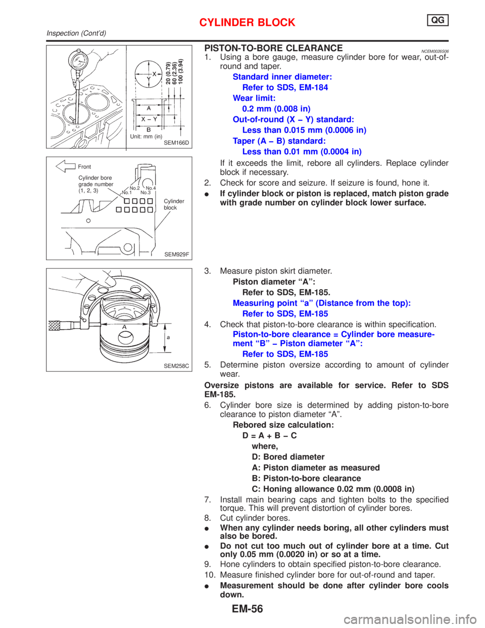
PISTON-TO-BORE CLEARANCENCEM0026S061. Using a bore gauge, measure cylinder bore for wear, out-of-
round and taper.
Standard inner diameter:
Refer to SDS, EM-184
Wear limit:
0.2 mm (0.008 in)
Out-of-round (X þ Y) standard:
Less than 0.015 mm (0.0006 in)
Taper (A þ B) standard:
Less than 0.01 mm (0.0004 in)
If it exceeds the limit, rebore all cylinders. Replace cylinder
block if necessary.
2. Check for score and seizure. If seizure is found, hone it.
IIf cylinder block or piston is replaced, match piston grade
with grade number on cylinder block lower surface.
3. Measure piston skirt diameter.
Piston diameter ªAº:
Refer to SDS, EM-185.
Measuring point ªaº (Distance from the top):
Refer to SDS, EM-185
4. Check that piston-to-bore clearance is within specification.
Piston-to-bore clearance = Cylinder bore measure-
ment ªBº þ Piston diameter ªAº:
Refer to SDS, EM-185
5. Determine piston oversize according to amount of cylinder
wear.
Oversize pistons are available for service. Refer to SDS
EM-185.
6. Cylinder bore size is determined by adding piston-to-bore
clearance to piston diameter ªAº.
Rebored size calculation:
D=A+BþC
where,
D: Bored diameter
A: Piston diameter as measured
B: Piston-to-bore clearance
C: Honing allowance 0.02 mm (0.0008 in)
7. Install main bearing caps and tighten bolts to the specified
torque. This will prevent distortion of cylinder bores.
8. Cut cylinder bores.
IWhen any cylinder needs boring, all other cylinders must
also be bored.
IDo not cut too much out of cylinder bore at a time. Cut
only 0.05 mm (0.0020 in) or so at a time.
9. Hone cylinders to obtain specified piston-to-bore clearance.
10. Measure finished cylinder bore for out-of-round and taper.
IMeasurement should be done after cylinder bore cools
down.
SEM166D
20 (0.79)
60 (2.36)
100 (3.94)
Unit: mm (in)
SEM929F Front
Cylinder bore
grade number
(1, 2, 3)
Cylinder
block
No.2
No.4
No.1 No.3
SEM258C
CYLINDER BLOCKQG
Inspection (Cont'd)
EM-56
Page 1598 of 2267
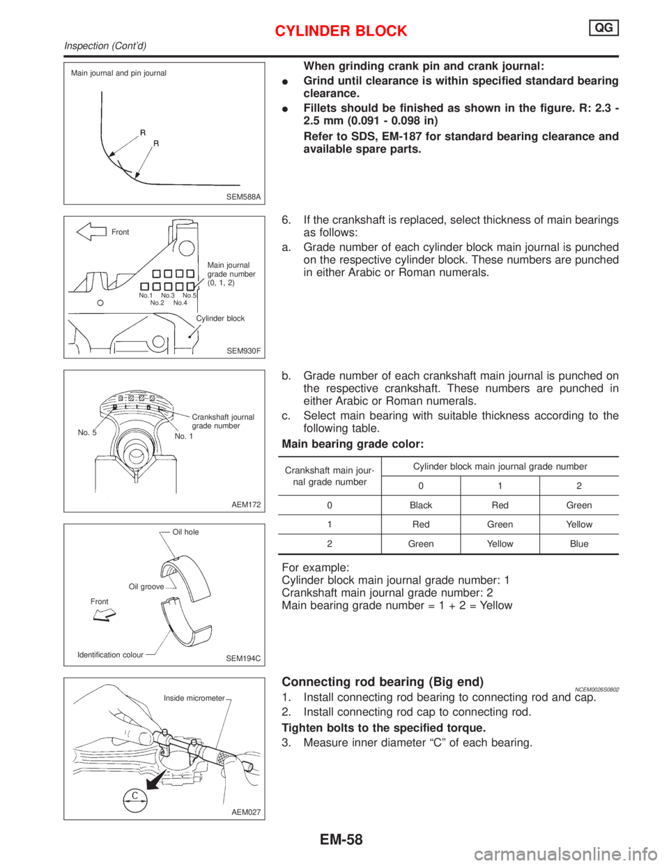
When grinding crank pin and crank journal:
IGrind until clearance is within specified standard bearing
clearance.
IFillets should be finished as shown in the figure. R: 2.3 -
2.5 mm (0.091 - 0.098 in)
Refer to SDS, EM-187 for standard bearing clearance and
available spare parts.
6. If the crankshaft is replaced, select thickness of main bearings
as follows:
a. Grade number of each cylinder block main journal is punched
on the respective cylinder block. These numbers are punched
in either Arabic or Roman numerals.
b. Grade number of each crankshaft main journal is punched on
the respective crankshaft. These numbers are punched in
either Arabic or Roman numerals.
c. Select main bearing with suitable thickness according to the
following table.
Main bearing grade color:
Crankshaft main jour-
nal grade numberCylinder block main journal grade number
012
0 Black Red Green
1 Red Green Yellow
2 Green Yellow Blue
For example:
Cylinder block main journal grade number: 1
Crankshaft main journal grade number: 2
Main bearing grade number=1+2=Yellow
Connecting rod bearing (Big end)NCEM0026S08021. Install connecting rod bearing to connecting rod and cap.
2. Install connecting rod cap to connecting rod.
Tighten bolts to the specified torque.
3. Measure inner diameter ªCº of each bearing.
SEM588A Main journal and pin journal
SEM930F Front
Main journal
grade number
(0, 1, 2)
Cylinder block
No.1 No.3 No.5
No.2 No.4
AEM172 Crankshaft journal
grade number
No. 1 No. 5
SEM194C Oil hole
Oil groove
Identification colourFront
AEM027 Inside micrometer
CYLINDER BLOCKQG
Inspection (Cont'd)
EM-58
Page 1601 of 2267
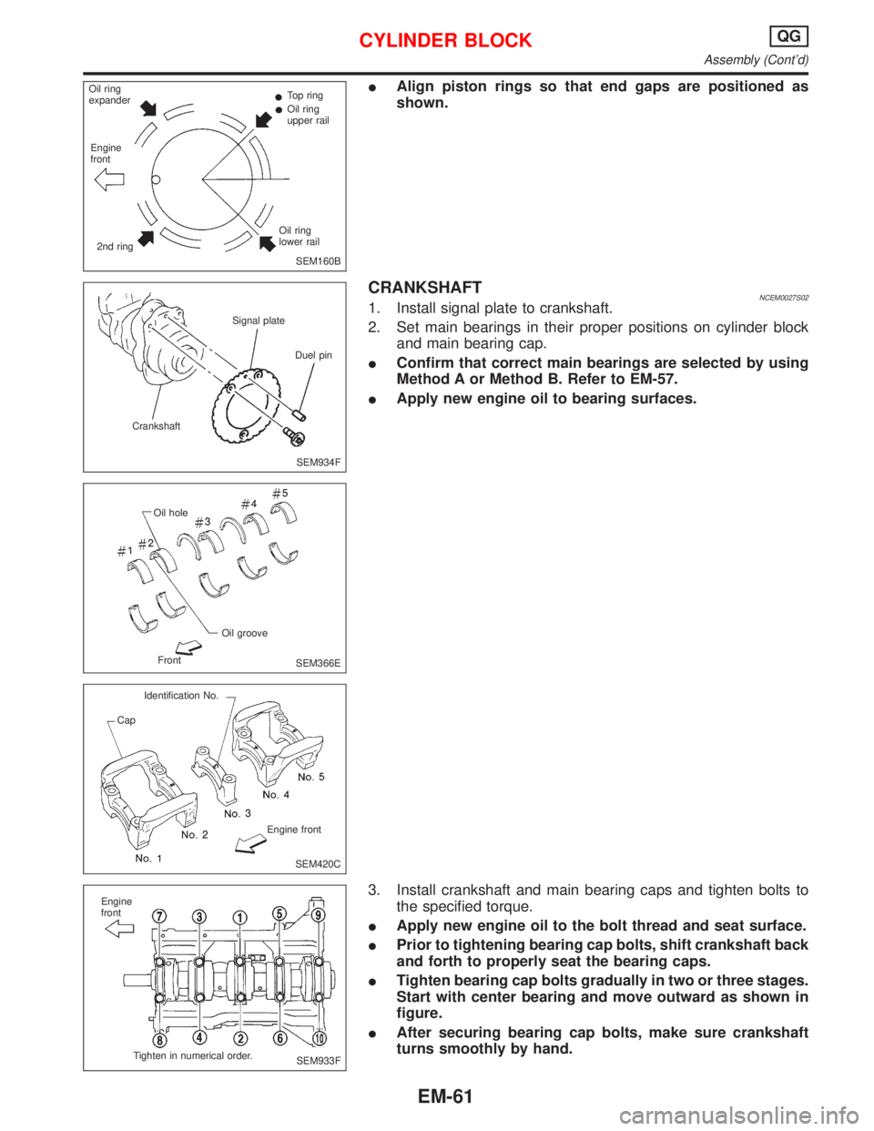
IAlign piston rings so that end gaps are positioned as
shown.
CRANKSHAFTNCEM0027S021. Install signal plate to crankshaft.
2. Set main bearings in their proper positions on cylinder block
and main bearing cap.
IConfirm that correct main bearings are selected by using
Method A or Method B. Refer to EM-57.
IApply new engine oil to bearing surfaces.
3. Install crankshaft and main bearing caps and tighten bolts to
the specified torque.
IApply new engine oil to the bolt thread and seat surface.
IPrior to tightening bearing cap bolts, shift crankshaft back
and forth to properly seat the bearing caps.
ITighten bearing cap bolts gradually in two or three stages.
Start with center bearing and move outward as shown in
figure.
IAfter securing bearing cap bolts, make sure crankshaft
turns smoothly by hand.
SEM160B Oil ring
expanderTop ring
Oil ring
upper rail
Oil ring
lower rail
2nd ring Engine
front
SEM934F CrankshaftSignal plate
Duel pin
SEM366E Oil hole
Oil groove
Front
SEM420C Identification No.
Cap
Engine front
SEM933F Engine
front
Tighten in numerical order.
CYLINDER BLOCKQG
Assembly (Cont'd)
EM-61
Page 1620 of 2267
IMating mark color on timing chain.
1: Golden
2, 3: White
3. Install timing chain and timing chain guides.
4. Install camshaft sprockets and timing chain on them.
Line up mating marks on timing chain with mating marks
on camshaft sprockets.
ILock camshafts as shown in figure and tighten to specified
torque.
: 137 - 157 N×m (14.0 - 16.0 kg-m, 101 - 116 ft-lb)
Apply new engine oil to threads and seating surfaces of cam-
shaft sprocket bolts before installing them.
SEM500E 20 rollers
Mating mark
48 rollers
Mating mark 56 rollers Mating mark
SEM982CA
SEM048G Mating mark
Mating mark
.RH camshaft sprocket.LH camshaft sprocket Mating mark
Mating mark
SEM049G
TIMING CHAINSR20DE
Installation (Cont'd)
EM-80
Page 1632 of 2267
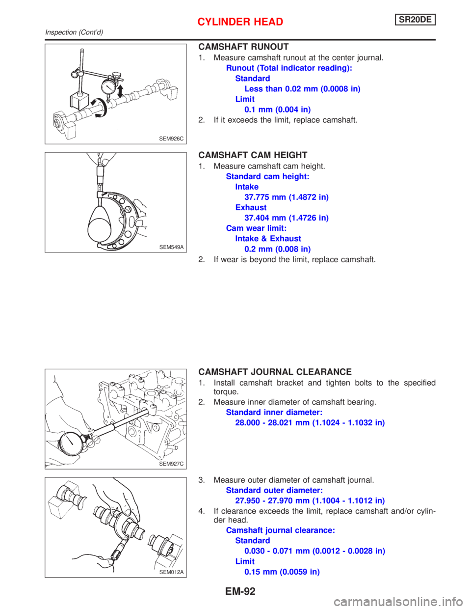
CAMSHAFT RUNOUT
1. Measure camshaft runout at the center journal.
Runout (Total indicator reading):
Standard
Less than 0.02 mm (0.0008 in)
Limit
0.1 mm (0.004 in)
2. If it exceeds the limit, replace camshaft.
CAMSHAFT CAM HEIGHT
1. Measure camshaft cam height.
Standard cam height:
Intake
37.775 mm (1.4872 in)
Exhaust
37.404 mm (1.4726 in)
Cam wear limit:
Intake & Exhaust
0.2 mm (0.008 in)
2. If wear is beyond the limit, replace camshaft.
CAMSHAFT JOURNAL CLEARANCE
1. Install camshaft bracket and tighten bolts to the specified
torque.
2. Measure inner diameter of camshaft bearing.
Standard inner diameter:
28.000 - 28.021 mm (1.1024 - 1.1032 in)
3. Measure outer diameter of camshaft journal.
Standard outer diameter:
27.950 - 27.970 mm (1.1004 - 1.1012 in)
4. If clearance exceeds the limit, replace camshaft and/or cylin-
der head.
Camshaft journal clearance:
Standard
0.030 - 0.071 mm (0.0012 - 0.0028 in)
Limit
0.15 mm (0.0059 in)
SEM926C
SEM549A
SEM927C
.SEM012A
CYLINDER HEADSR20DE
Inspection (Cont'd)
EM-92