1999 NISSAN PRIMERA engine coolant
[x] Cancel search: engine coolantPage 384 of 2267
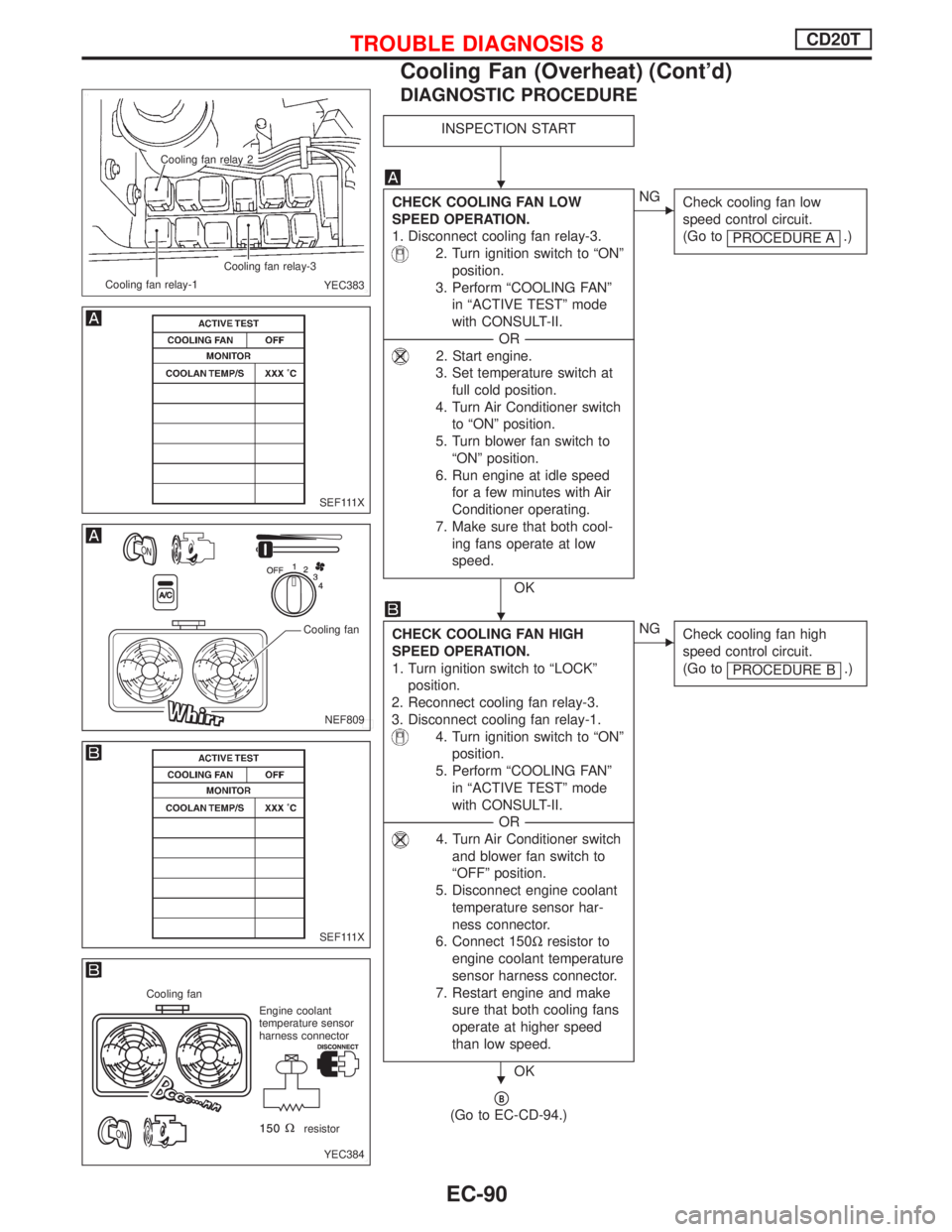
DIAGNOSTIC PROCEDURE
INSPECTION START
CHECK COOLING FAN LOW
SPEED OPERATION.
1. Disconnect cooling fan relay-3.
2. Turn ignition switch to ªONº
position.
3. Perform ªCOOLING FANº
in ªACTIVE TESTº mode
with CONSULT-II.
-------------------------------------------------------------------------------------------------------------------------OR-------------------------------------------------------------------------------------------------------------------------
2. Start engine.
3. Set temperature switch at
full cold position.
4. Turn Air Conditioner switch
to ªONº position.
5. Turn blower fan switch to
ªONº position.
6. Run engine at idle speed
for a few minutes with Air
Conditioner operating.
7. Make sure that both cool-
ing fans operate at low
speed.
OK
ENG
Check cooling fan low
speed control circuit.
(Go to
PROCEDURE A
.)
CHECK COOLING FAN HIGH
SPEED OPERATION.
1. Turn ignition switch to ªLOCKº
position.
2. Reconnect cooling fan relay-3.
3. Disconnect cooling fan relay-1.
4. Turn ignition switch to ªONº
position.
5. Perform ªCOOLING FANº
in ªACTIVE TESTº mode
with CONSULT-II.
-------------------------------------------------------------------------------------------------------------------------OR-------------------------------------------------------------------------------------------------------------------------
4. Turn Air Conditioner switch
and blower fan switch to
ªOFFº position.
5. Disconnect engine coolant
temperature sensor har-
ness connector.
6. Connect 150Wresistor to
engine coolant temperature
sensor harness connector.
7. Restart engine and make
sure that both cooling fans
operate at higher speed
than low speed.
OK
ENG
Check cooling fan high
speed control circuit.
(Go to
PROCEDURE B
.)
pB
(Go to EC-CD-94.)
.Cooling fan relay 2
Cooling fan relay-1Cooling fan relay-3
YEC383
SEF111X
NEF809
Cooling fan
SEF111X
YEC384
Cooling fan
Engine coolant
temperature sensor
harness connector
resistor
H
H
H
TROUBLE DIAGNOSIS 8CD20T
Cooling Fan (Overheat) (Cont'd)
EC-90
Page 388 of 2267
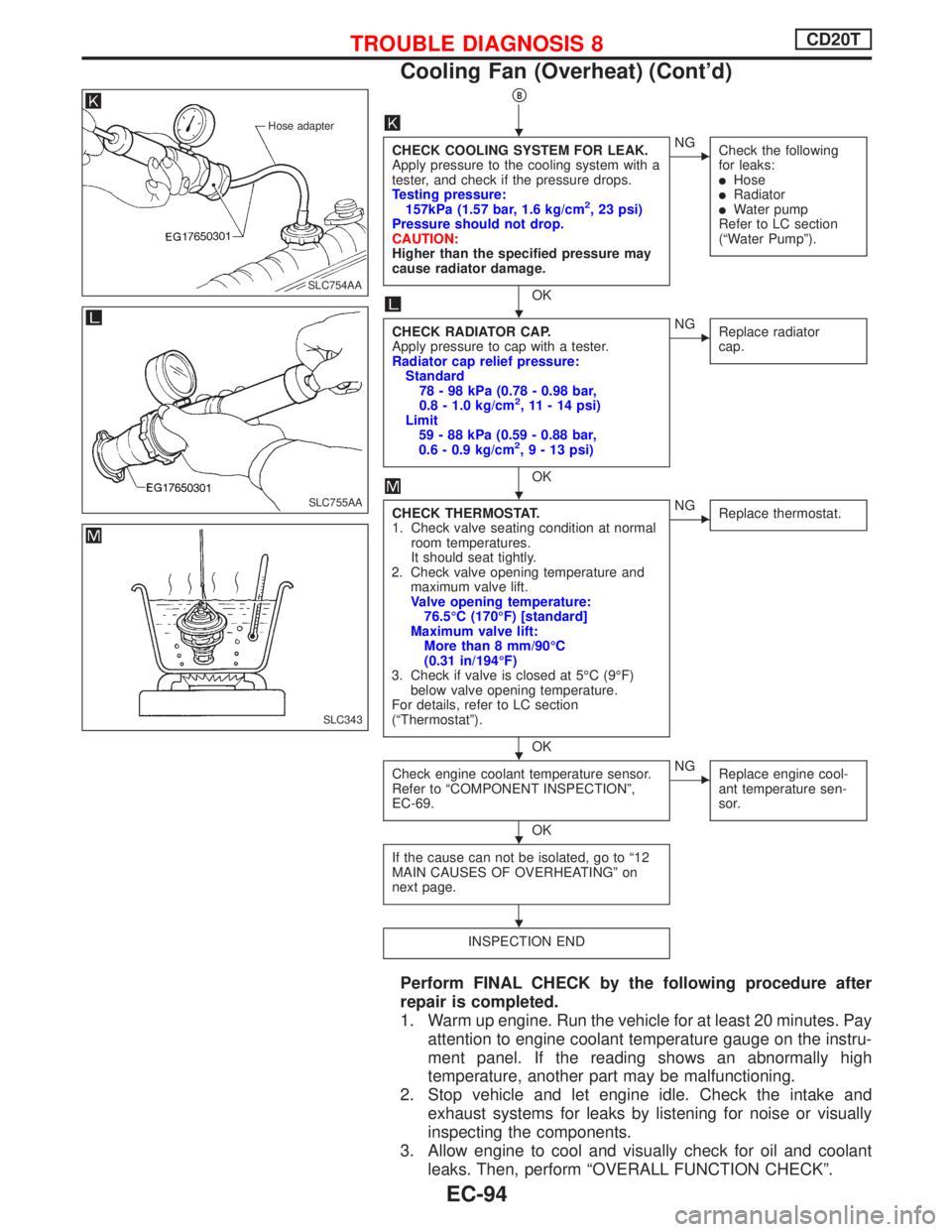
pB
CHECK COOLING SYSTEM FOR LEAK.
Apply pressure to the cooling system with a
tester, and check if the pressure drops.
Testing pressure:
157kPa (1.57 bar, 1.6 kg/cm
2, 23 psi)
Pressure should not drop.
CAUTION:
Higher than the specified pressure may
cause radiator damage.
OK
ENG
Check the following
for leaks:
lHoselRadiatorlWater pump
Refer to LC section
(ªWater Pumpº).
CHECK RADIATOR CAP.
Apply pressure to cap with a tester.
Radiator cap relief pressure:
Standard
78 - 98 kPa (0.78 - 0.98 bar,
0.8 - 1.0 kg/cm
2, 11 - 14 psi)
Limit
59 - 88 kPa (0.59 - 0.88 bar,
0.6 - 0.9 kg/cm
2,9-13psi)
OK
ENG
Replace radiator
cap.
CHECK THERMOSTAT.
1. Check valve seating condition at normal
room temperatures.
It should seat tightly.
2. Check valve opening temperature and
maximum valve lift.
Valve opening temperature:
76.5ÉC (170ÉF) [standard]
Maximum valve lift:
More than 8 mm/90ÉC
(0.31 in/194ÉF)
3. Check if valve is closed at 5ÉC (9ÉF)
below valve opening temperature.
For details, refer to LC section
(ªThermostatº).
OK
ENG
Replace thermostat.
Check engine coolant temperature sensor.
Refer to ªCOMPONENT INSPECTIONº,
EC-69.
OK
ENG
Replace engine cool-
ant temperature sen-
sor.
If the cause can not be isolated, go to ª12
MAIN CAUSES OF OVERHEATINGº on
next page.
INSPECTION END
Perform FINAL CHECK by the following procedure after
repair is completed.
1. Warm up engine. Run the vehicle for at least 20 minutes. Pay
attention to engine coolant temperature gauge on the instru-
ment panel. If the reading shows an abnormally high
temperature, another part may be malfunctioning.
2. Stop vehicle and let engine idle. Check the intake and
exhaust systems for leaks by listening for noise or visually
inspecting the components.
3. Allow engine to cool and visually check for oil and coolant
leaks. Then, perform ªOVERALL FUNCTION CHECKº.
Hose adapter
.SLC754AA
SLC755AA
SLC343
H
H
H
H
H
H
TROUBLE DIAGNOSIS 8CD20T
Cooling Fan (Overheat) (Cont'd)
EC-94
Page 389 of 2267
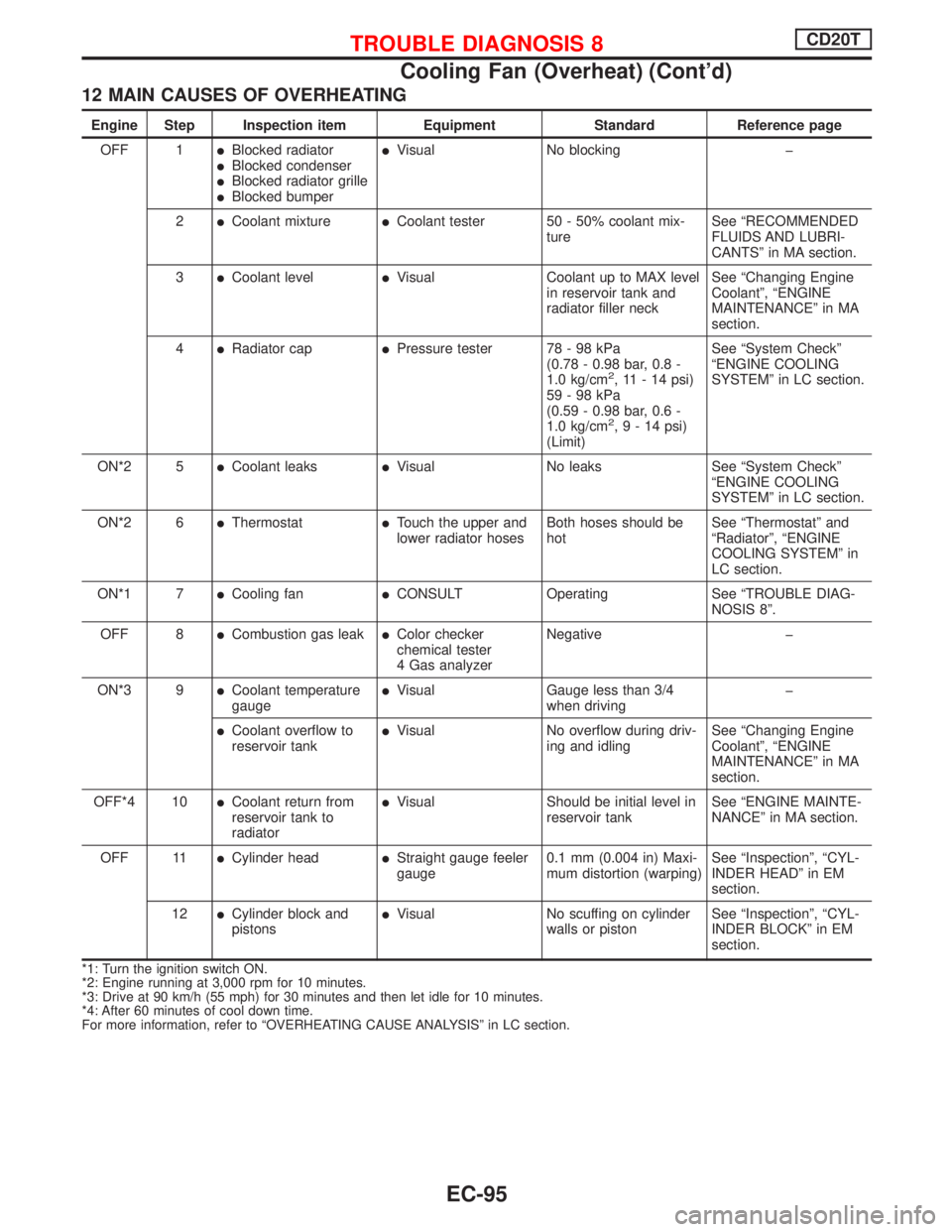
12 MAIN CAUSES OF OVERHEATING
Engine Step Inspection item Equipment Standard Reference page
OFF 1
lBlocked radiatorlBlocked condenserlBlocked radiator grillelBlocked bumper
lVisual No blocking þ
2
lCoolant mixturelCoolant tester 50 - 50% coolant mix-
tureSee ªRECOMMENDED
FLUIDS AND LUBRI-
CANTSº in MA section.
3
lCoolant levellVisual Coolant up to MAX level
in reservoir tank and
radiator filler neckSee ªChanging Engine
Coolantº, ªENGINE
MAINTENANCEº in MA
section.
4
lRadiator caplPressure tester 78 - 98 kPa
(0.78 - 0.98 bar, 0.8 -
1.0 kg/cm
2, 11 - 14 psi)
59-98kPa
(0.59 - 0.98 bar, 0.6 -
1.0 kg/cm
2,9-14psi)
(Limit)See ªSystem Checkº
ªENGINE COOLING
SYSTEMº in LC section.
ON*2 5
lCoolant leakslVisual No leaks See ªSystem Checkº
ªENGINE COOLING
SYSTEMº in LC section.
ON*2 6
lThermostatlTouch the upper and
lower radiator hosesBoth hoses should be
hotSee ªThermostatº and
ªRadiatorº, ªENGINE
COOLING SYSTEMº in
LC section.
ON*1 7
lCooling fanlCONSULT Operating See ªTROUBLE DIAG-
NOSIS 8º.
OFF 8
lCombustion gas leaklColor checker
chemical tester
4 Gas analyzerNegative þ
ON*3 9
lCoolant temperature
gaugelVisual Gauge less than 3/4
when drivingþ
lCoolant overflow to
reservoir tanklVisual No overflow during driv-
ing and idlingSee ªChanging Engine
Coolantº, ªENGINE
MAINTENANCEº in MA
section.
OFF*4 10
lCoolant return from
reservoir tank to
radiatorlVisual Should be initial level in
reservoir tankSee ªENGINE MAINTE-
NANCEº in MA section.
OFF 11
lCylinder headlStraight gauge feeler
gauge0.1 mm (0.004 in) Maxi-
mum distortion (warping)See ªInspectionº, ªCYL-
INDER HEADº in EM
section.
12
lCylinder block and
pistonslVisual No scuffing on cylinder
walls or pistonSee ªInspectionº, ªCYL-
INDER BLOCKº in EM
section.
*1: Turn the ignition switch ON.
*2: Engine running at 3,000 rpm for 10 minutes.
*3: Drive at 90 km/h (55 mph) for 30 minutes and then let idle for 10 minutes.
*4: After 60 minutes of cool down time.
For more information, refer to ªOVERHEATING CAUSE ANALYSISº in LC section.
TROUBLE DIAGNOSIS 8CD20T
Cooling Fan (Overheat) (Cont'd)
EC-95
Page 412 of 2267
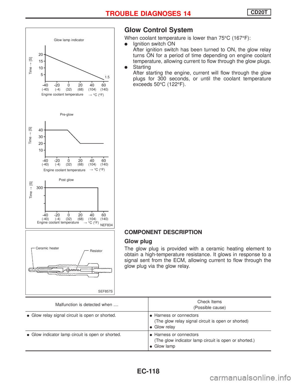
Glow Control System
When coolant temperature is lower than 75ÉC (167ÉF):
lIgnition switch ON
After ignition switch has been turned to ON, the glow relay
turns ON for a period of time depending on engine coolant
temperature, allowing current to flow through the glow plugs.
lStarting
After starting the engine, current will flow through the glow
plugs for 300 seconds, or until the coolant temperature
exceeds 50ÉC (122ÉF).
COMPONENT DESCRIPTION
Glow plug
The glow plug is provided with a ceramic heating element to
obtain a high-temperature resistance. It glows in response to a
signal sent from the ECM, allowing current to flow through the
glow plug via the glow relay.
Malfunction is detected when ....Check Items
(Possible cause)
lGlow relay signal circuit is open or shorted.lHarness or connectors
(The glow relay signal circuit is open or shorted)
lGlow relay
lGlow indicator lamp circuit is open or shorted.lHarness or connectors
(The glow indicator lamp circuit is open or shorted.)
lGlow lamp
Glow lamp indicator
Time,[S]
.
Engine coolant temperature
Pre-glow
Time,[S]
Engine coolant temperature.
Post glow
.Time,[S]
Engine coolant temperature
.1.5
.(-40) (-4) (32) (68) (104) (140)
.(-40) (-4) (32) (68) (104) (140)
.(-40) (-4) (32) (68) (104) (140),ÉC (ÉF).,ÉC (ÉF)
.,ÉC (ÉF)
NEF834
.
.
SEF857S Ceramic heater
Resistor
TROUBLE DIAGNOSES 14CD20T
EC-118
Page 418 of 2267
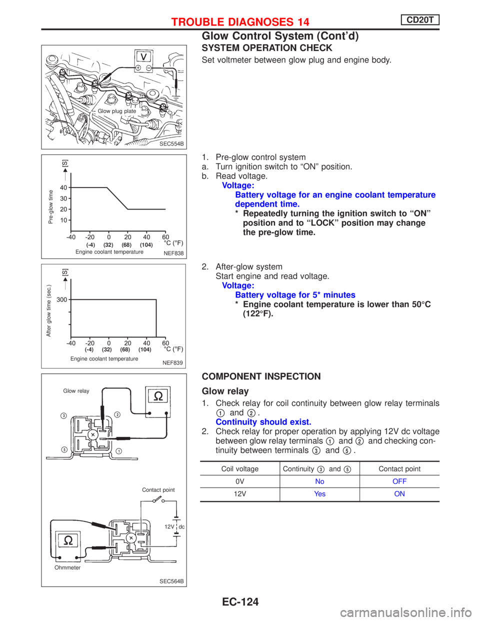
SYSTEM OPERATION CHECK
Set voltmeter between glow plug and engine body.
1. Pre-glow control system
a. Turn ignition switch to ªONº position.
b. Read voltage.
Voltage:
Battery voltage for an engine coolant temperature
dependent time.
* Repeatedly turning the ignition switch to ªONº
position and to ªLOCKº position may change
the pre-glow time.
2. After-glow system
Start engine and read voltage.
Voltage:
Battery voltage for 5* minutes
* Engine coolant temperature is lower than 50ÉC
(122ÉF).
COMPONENT INSPECTION
Glow relay
1. Check relay for coil continuity between glow relay terminals
p1andp2.
Continuity should exist.
2. Check relay for proper operation by applying 12V dc voltage
between glow relay terminals
p1andp2and checking con-
tinuity between terminals
p3andp5.
Coil voltage Continuityp3andp5Contact point
0VNo OFF
12VYe s O N
SEC554B Glow plug plate
NEF838
Pre-glow time
Engine coolant temperature
.(-4) (32) (68) (104)
NEF839 Engine coolant temperature
After glow time (sec.)
.(-4) (32) (68) (104)
SEC564B OhmmeterGlow relay
Contact point
12V dc
p2
p1
p3
p5
TROUBLE DIAGNOSES 14CD20T
Glow Control System (Cont'd)
EC-124
Page 420 of 2267
Air Conditioner Cut Control
The Air Conditioner relay is controlled by the ECM. During the
following conditions, the ECM will cut the power supply towards
the air conditioner relay:
lStarting engine
lQuick acceleration from low speed
lUndershooting of idle speed
lHigh engine coolant temperature [above 107ÉC (225ÉF)].
lMalfunctioning of engine speed sensor, accelerator position
sensor or vehicle speed sensor when engine speed is below
2,100 rpm.
Malfunction is detected when ....Check Items
(Possible cause)
lAir conditioner relay signal circuit is shorted.lHarness or connectors
(The air conditioner relay signal circuit is shorted).
lAir conditioner relay
DIAGNOSTIC TROUBLE CONFIRMATION
PROCEDURE
1) Turn ignition switch and air conditioner switch to the
ªONº position.
2) Select ªDATA MONITORº mode with CONSULT-II.
3) Wait at least 2 seconds.
TROUBLE DIAGNOSES 15CD20T
EC-126
Page 423 of 2267
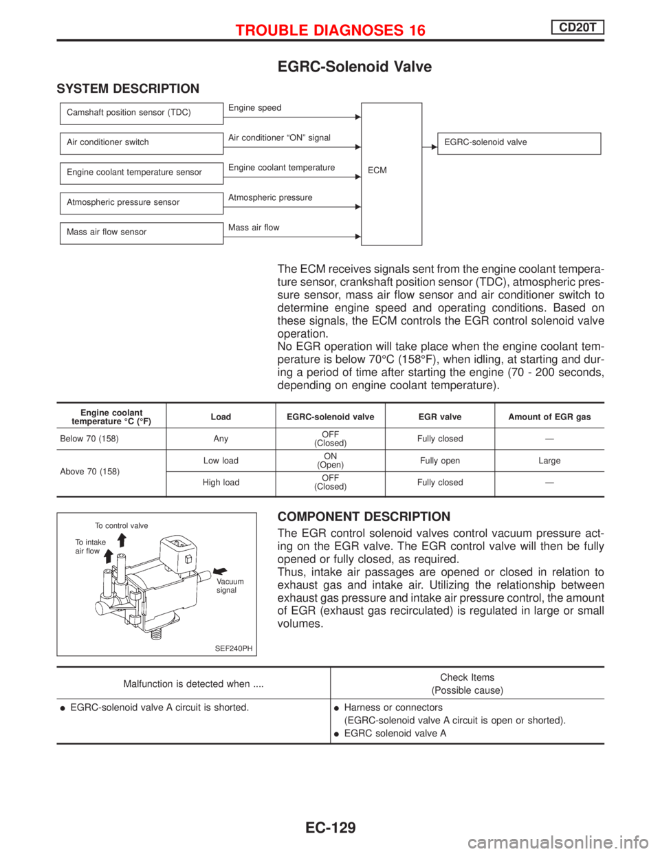
EGRC-Solenoid Valve
SYSTEM DESCRIPTION
Camshaft position sensor (TDC)EEngine speed
ECM
Air conditioner switchEAir conditioner ªONº signalEEGRC-solenoid valve
Engine coolant temperature sensorEEngine coolant temperature
Atmospheric pressure sensor
EAtmospheric pressure
Mass air flow sensor
EMass air flow
The ECM receives signals sent from the engine coolant tempera-
ture sensor, crankshaft position sensor (TDC), atmospheric pres-
sure sensor, mass air flow sensor and air conditioner switch to
determine engine speed and operating conditions. Based on
these signals, the ECM controls the EGR control solenoid valve
operation.
No EGR operation will take place when the engine coolant tem-
perature is below 70ÉC (158ÉF), when idling, at starting and dur-
ing a period of time after starting the engine (70 - 200 seconds,
depending on engine coolant temperature).
Engine coolant
temperature ÉC (ÉF)Load EGRC-solenoid valve EGR valve Amount of EGR gas
Below 70 (158) AnyOFF
(Closed)Fully closed Ð
Above 70 (158)Low loadON
(Open)Fully open Large
High loadOFF
(Closed)Fully closed Ð
COMPONENT DESCRIPTION
The EGR control solenoid valves control vacuum pressure act-
ing on the EGR valve. The EGR control valve will then be fully
opened or fully closed, as required.
Thus, intake air passages are opened or closed in relation to
exhaust gas and intake air. Utilizing the relationship between
exhaust gas pressure and intake air pressure control, the amount
of EGR (exhaust gas recirculated) is regulated in large or small
volumes.
Malfunction is detected when ....Check Items
(Possible cause)
lEGRC-solenoid valve A circuit is shorted.lHarness or connectors
(EGRC-solenoid valve A circuit is open or shorted).
lEGRC solenoid valve A
SEF240PH To control valve
To intake
air flow
Vacuum
signal
TROUBLE DIAGNOSES 16CD20T
EC-129
Page 441 of 2267
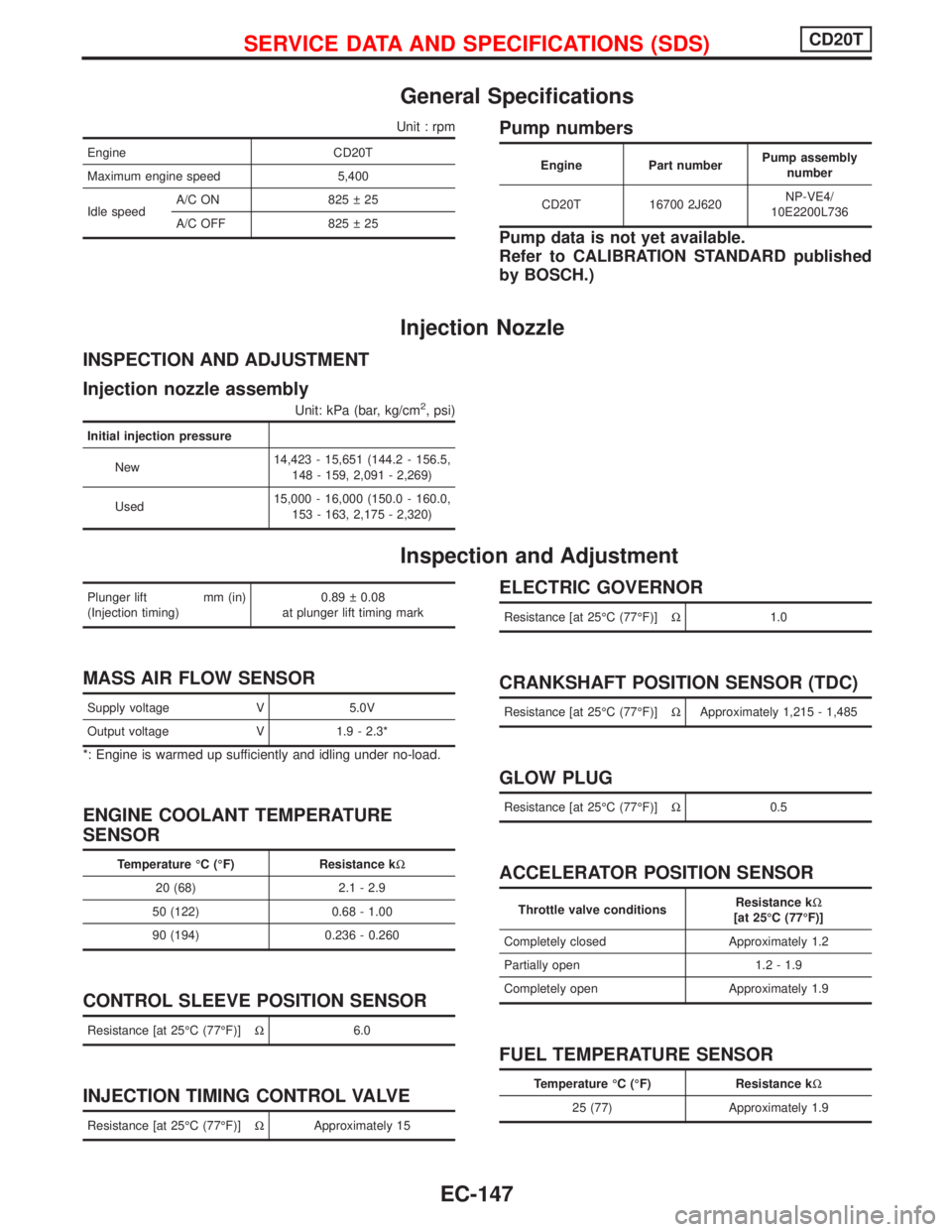
General Specifications
Unit : rpm
Engine CD20T
Maximum engine speed 5,400
Idle speedA/C ON 825 25
A/C OFF 825 25
Pump numbers
Engine Part numberPump assembly
number
CD20T 16700 2J620NP-VE4/
10E2200L736
Pump data is not yet available.
Refer to CALIBRATION STANDARD published
by BOSCH.)
Injection Nozzle
INSPECTION AND ADJUSTMENT
Injection nozzle assembly
Unit: kPa (bar, kg/cm2, psi)
Initial injection pressure
New14,423 - 15,651 (144.2 - 156.5,
148 - 159, 2,091 - 2,269)
Used15,000 - 16,000 (150.0 - 160.0,
153 - 163, 2,175 - 2,320)
Inspection and Adjustment
Plunger lift mm (in)
(Injection timing)0.89 0.08
at plunger lift timing mark
MASS AIR FLOW SENSOR
Supply voltage V 5.0V
Output voltage V 1.9 - 2.3*
*: Engine is warmed up sufficiently and idling under no-load.
ENGINE COOLANT TEMPERATURE
SENSOR
Temperature ÉC (ÉF) Resistance kW
20 (68) 2.1 - 2.9
50 (122) 0.68 - 1.00
90 (194) 0.236 - 0.260
CONTROL SLEEVE POSITION SENSOR
Resistance [at 25ÉC (77ÉF)]W6.0
INJECTION TIMING CONTROL VALVE
Resistance [at 25ÉC (77ÉF)]WApproximately 15
ELECTRIC GOVERNOR
Resistance [at 25ÉC (77ÉF)]W1.0
CRANKSHAFT POSITION SENSOR (TDC)
Resistance [at 25ÉC (77ÉF)]WApproximately 1,215 - 1,485
GLOW PLUG
Resistance [at 25ÉC (77ÉF)]W0.5
ACCELERATOR POSITION SENSOR
Throttle valve conditionsResistance kW
[at 25ÉC (77ÉF)]
Completely closed Approximately 1.2
Partially open 1.2 - 1.9
Completely open Approximately 1.9
FUEL TEMPERATURE SENSOR
Temperature ÉC (ÉF) Resistance kW
25 (77) Approximately 1.9
SERVICE DATA AND SPECIFICATIONS (SDS)CD20T
EC-147