1999 NISSAN PRIMERA engine coolant
[x] Cancel search: engine coolantPage 501 of 2267
![NISSAN PRIMERA 1999 Electronic Repair Manual DATA MONITOR MODENCEC0034S06
Monitored item [Unit]ECM
input
signalsMain
signalsDescription Remarks
ENG SPEED
[rpm]qqIIndicates the engine speed computed from the
POS signal of the crankshaft position NISSAN PRIMERA 1999 Electronic Repair Manual DATA MONITOR MODENCEC0034S06
Monitored item [Unit]ECM
input
signalsMain
signalsDescription Remarks
ENG SPEED
[rpm]qqIIndicates the engine speed computed from the
POS signal of the crankshaft position](/manual-img/5/57377/w960_57377-500.png)
DATA MONITOR MODENCEC0034S06
Monitored item [Unit]ECM
input
signalsMain
signalsDescription Remarks
ENG SPEED
[rpm]qqIIndicates the engine speed computed from the
POS signal of the crankshaft position sensor.IAccuracy becomes poor if
engine speed drops below the
idle rpm.
IIf the signal is interrupted while
the engine is running, an abnor-
mal value may be indicated.
MAS A/F SE-B1 [V]qqIThe signal voltage of the mass air flow sensor is
displayed.IWhen the engine is stopped, a
certain value is indicated.
COOLAN TEMP/S
[ÉC] or [ÉF]qqIThe engine coolant temperature (determined by
the signal voltage of the engine coolant tem-
perature sensor) is displayed.IWhen the engine coolant tem-
perature sensor is open or
short-circuited, ECM enters fail-
safe mode. The engine coolant
temperature determined by the
ECM is displayed.
HO2S1 (B1) [V]qqIThe signal voltage of the heated oxygen sensor
1 (front) is displayed.
HO2S2 (B1) [V]qIThe signal voltage of the heated oxygen sensor
2 (rear) is displayed.
HO2S1 MNTR (B1)
[RICH/LEAN]qIDisplay of heated oxygen sensor 1 (front) signal
during air-fuel ratio feedback control:
RICH ... means the mixture became ªrichº, and
control is being affected toward a leaner mix-
ture.
LEAN ... means the mixture became ªleanº, and
control is being affected toward a rich mixture.IAfter turning ON the ignition
switch, ªRICHº is displayed until
air-fuel mixture ratio feedback
control begins.
IWhen the air-fuel ratio feedback
is clamped, the value just
before the clamping is dis-
played continuously.
HO2S2 MNTR (B1)
[RICH/LEAN]qIDisplay of heated oxygen sensor 2 (rear) signal:
RICH ... means the amount of oxygen after
three way catalyst is relatively small.
LEAN ... means the amount of oxygen after
three way catalyst is relatively large.IWhen the engine is stopped, a
certain value is indicated.
VHCL SPEED SE
[km/h] or [mph]qqIThe vehicle speed computed from the vehicle
speed sensor signal or ABS actuator and elec-
tric unit (control unit) signal is displayed.
BATTERY VOLT [V]qIThe power supply voltage of ECM is displayed.
THRTL POS SEN [V]qqIThe throttle position sensor signal voltage is dis-
played.
EGR TEMP SEN [V]
(If so equipped)qqIThe signal voltage of the EGR temperature sen-
sor is displayed.
INT/A TEMP SE
[ÉC] or [ÉF]qIThe intake air temperature determined by the
signal voltage of the intake air temperature sen-
sor is indicated.
START SIGNAL
[ON/OFF]qqIIndicates [ON/OFF] condition from the starter
signal.IAfter starting the engine, [OFF]
is displayed regardless of the
starter signal.
CLSD THL POS
[ON/OFF]qqIIndicates idle position [ON/OFF] computed by
ECM according to the throttle position sensor
signal.
ON BOARD DIAGNOSTIC SYSTEM DESCRIPTIONQG16I18DE
CONSULT-II (Cont'd)
EC-59
Page 504 of 2267
![NISSAN PRIMERA 1999 Electronic Repair Manual DATA MONITOR (SPEC) MODENLEC1365S07
Monitored item [Unit]ECM
input
signalsMain
signalsDescription Remarks
MAS A/F SE-B1 [V]qqIThe signal voltage of the mass air flow sen-
sor specification is displaye NISSAN PRIMERA 1999 Electronic Repair Manual DATA MONITOR (SPEC) MODENLEC1365S07
Monitored item [Unit]ECM
input
signalsMain
signalsDescription Remarks
MAS A/F SE-B1 [V]qqIThe signal voltage of the mass air flow sen-
sor specification is displaye](/manual-img/5/57377/w960_57377-503.png)
DATA MONITOR (SPEC) MODENLEC1365S07
Monitored item [Unit]ECM
input
signalsMain
signalsDescription Remarks
MAS A/F SE-B1 [V]qqIThe signal voltage of the mass air flow sen-
sor specification is displayed.IWhen the engine is running, specifi-
cation range is indicated.
B/FUEL SCHDL
[msec]IªBase fuel scheduleº indicates the fuel injec-
tion pulse width programmed into ECM,
prior to any learned on board correction.IWhen the engine is running, specifi-
cation range is indicated.
A/F ALPHA-B1 [%]qIIndicates the mean value of the air-fuel ratio
feedback correction factor per cycle.IWhen the engine is running, specifi-
cation range is indicated.
IThis data also includes the data for
the air-fuel ratio learning control.
NOTE:
Any monitored item that does not match the vehicle being diagnosed is deleted from the display automatically.
ACTIVE TEST MODENCEC0034S07
TEST ITEM CONDITION JUDGEMENT CHECK ITEM (REMEDY)
FUEL INJECTIONIEngine: Return to the original
trouble condition
IChange the amount of fuel injec-
tion using CONSULT-II.If trouble symptom disappears, see
CHECK ITEM.IHarness and connector
IFuel injectors
IHeated oxygen sensor 1 (front)
IACV-AAC/V
OPENINGIEngine: After warming up, idle
the engine.
IChange the IACV-AAC valve
opening steps using CONSULT-
II.Engine speed changes according
to the opening steps.IHarness and connector
IIACV-AAC valve
ENG COOLANT
TEMPIEngine: Return to the original
trouble condition
IChange the engine coolant tem-
perature indication using CON-
SULT-II.If trouble symptom disappears, see
CHECK ITEM.IHarness and connector
IEngine coolant temperature sen-
sor
IFuel injectors
IGNITION TIMINGIEngine: Return to the original
trouble condition
ITiming light: Set
IRetard the ignition timing using
CONSULT-II.If trouble symptom disappears, see
CHECK ITEM.IªBase Idle Air Volume Initializingº
(Refer to EC-QG-33.)
ICamshaft position sensor
(PHASE)
ICrankshaft position sensor
(POS)
IEngine component parts and
installing conditions
POWER BAL-
ANCEIEngine: After warming up, idle
the engine.
IAir conditioner switch ªOFFº
IShift lever ªNº
ICut off each injector signal one
at a time using CONSULT-II.Engine runs rough or dies.IHarness and connector
ICompression
IInjectors
IPower transistor
ISpark plugs
IIgnition coils
COOLING FANIIgnition switch: ON
ITurn the cooling fan ªONº and
ªOFFº using CONSULT-II.Cooling fan moves and stops.IHarness and connector
ICooling fan motor
FUEL PUMP
RELAYIIgnition switch: ON
(Engine stopped)
ITurn the fuel pump relay ªONº
and ªOFFº using CONSULT-II
and listen to operating sound.Fuel pump relay makes the operat-
ing sound.IHarness and connector
IFuel pump relay
ON BOARD DIAGNOSTIC SYSTEM DESCRIPTIONQG16I18DE
CONSULT-II (Cont'd)
EC-62
Page 522 of 2267
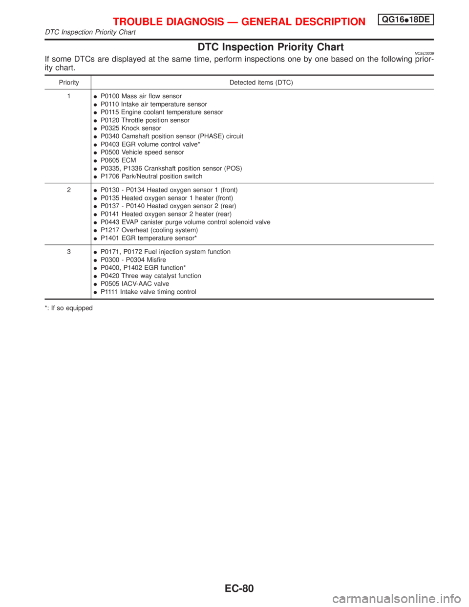
DTC Inspection Priority ChartNCEC0039If some DTCs are displayed at the same time, perform inspections one by one based on the following prior-
ity chart.
Priority Detected items (DTC)
1IP0100 Mass air flow sensor
IP0110 Intake air temperature sensor
IP0115 Engine coolant temperature sensor
IP0120 Throttle position sensor
IP0325 Knock sensor
IP0340 Camshaft position sensor (PHASE) circuit
IP0403 EGR volume control valve*
IP0500 Vehicle speed sensor
IP0605 ECM
IP0335, P1336 Crankshaft position sensor (POS)
IP1706 Park/Neutral position switch
2IP0130 - P0134 Heated oxygen sensor 1 (front)
IP0135 Heated oxygen sensor 1 heater (front)
IP0137 - P0140 Heated oxygen sensor 2 (rear)
IP0141 Heated oxygen sensor 2 heater (rear)
IP0443 EVAP canister purge volume control solenoid valve
IP1217 Overheat (cooling system)
IP1401 EGR temperature sensor*
3IP0171, P0172 Fuel injection system function
IP0300 - P0304 Misfire
IP0400, P1402 EGR function*
IP0420 Three way catalyst function
IP0505 IACV-AAC valve
IP 1111Intake valve timing control
*: If so equipped
TROUBLE DIAGNOSIS Ð GENERAL DESCRIPTIONQG16I18DE
DTC Inspection Priority Chart
EC-80
Page 523 of 2267
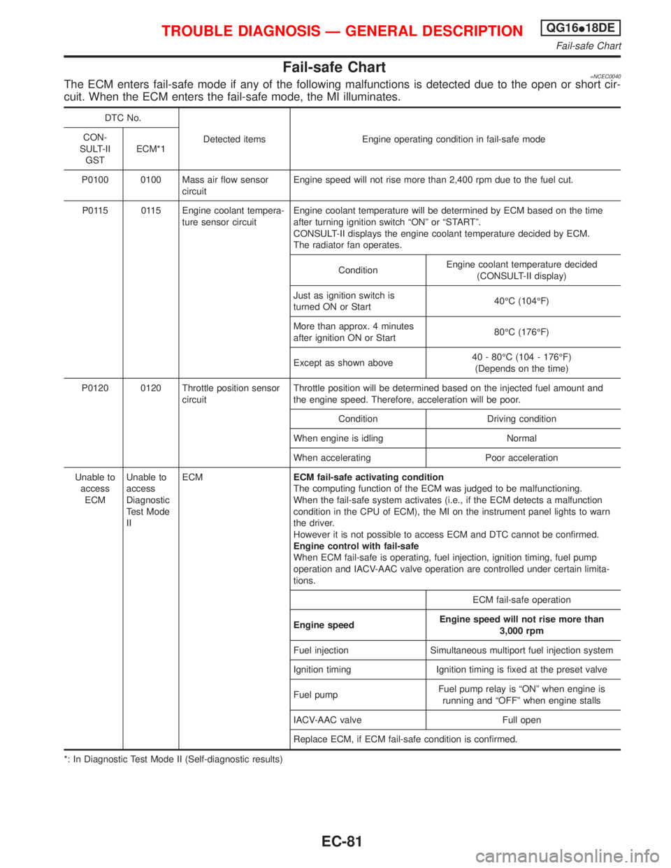
Fail-safe Chart=NCEC0040The ECM enters fail-safe mode if any of the following malfunctions is detected due to the open or short cir-
cuit. When the ECM enters the fail-safe mode, the MI illuminates.
DTC No.
Detected items Engine operating condition in fail-safe mode CON-
SULT-II
GSTECM*1
P0100 0100 Mass air flow sensor
circuitEngine speed will not rise more than 2,400 rpm due to the fuel cut.
P0115 0115 Engine coolant tempera-
ture sensor circuitEngine coolant temperature will be determined by ECM based on the time
after turning ignition switch ªONº or ªSTARTº.
CONSULT-II displays the engine coolant temperature decided by ECM.
The radiator fan operates.
ConditionEngine coolant temperature decided
(CONSULT-II display)
Just as ignition switch is
turned ON or Start40ÉC (104ÉF)
More than approx. 4 minutes
after ignition ON or Start80ÉC (176ÉF)
Except as shown above40 - 80ÉC (104 - 176ÉF)
(Depends on the time)
P0120 0120 Throttle position sensor
circuitThrottle position will be determined based on the injected fuel amount and
the engine speed. Therefore, acceleration will be poor.
Condition Driving condition
When engine is idling Normal
When accelerating Poor acceleration
Unable to
access
ECMUnable to
access
Diagnostic
Test Mode
IIECMECM fail-safe activating condition
The computing function of the ECM was judged to be malfunctioning.
When the fail-safe system activates (i.e., if the ECM detects a malfunction
condition in the CPU of ECM), the MI on the instrument panel lights to warn
the driver.
However it is not possible to access ECM and DTC cannot be confirmed.
Engine control with fail-safe
When ECM fail-safe is operating, fuel injection, ignition timing, fuel pump
operation and IACV-AAC valve operation are controlled under certain limita-
tions.
ECM fail-safe operation
Engine speedEngine speed will not rise more than
3,000 rpm
Fuel injection Simultaneous multiport fuel injection system
Ignition timing Ignition timing is fixed at the preset valve
Fuel pumpFuel pump relay is ªONº when engine is
running and ªOFFº when engine stalls
IACV-AAC valve Full open
Replace ECM, if ECM fail-safe condition is confirmed.
*: In Diagnostic Test Mode II (Self-diagnostic results)
TROUBLE DIAGNOSIS Ð GENERAL DESCRIPTIONQG16I18DE
Fail-safe Chart
EC-81
Page 525 of 2267
SYMPTOM
Reference
page
HARD/NO START/RESTART (EXCP. HA)
ENGINE STALL
HESITATION/SURGING/FLAT SPOT
SPARK KNOCK/DETONATION
LACK OF POWER/POOR ACCELERATION
HIGH IDLE/LOW IDLE
ROUGH IDLE/HUNTING
IDLING VIBRATION
SLOW/NO RETURN TO IDLE
OVERHEATS/WATER TEMPERATURE HIGH
EXCESSIVE FUEL CONSUMPTION
EXCESSIVE OIL CONSUMPTION
BATTERY DEAD (UNDER CHARGE)
Warranty symptom code AA AB AC AD AE AF AG AH AJ AK AL AM HA
Crankshaft position sensor (POS) circuit 2 2 EC-QG-232
Camshaft position sensor (PHASE) circuit 3 2 3 EC-QG-238
Mass air flow sensor circuit11222 22 2EC-QG-110
Heated oxygen sensor 1 (front) circuit1232 22 2EC-QG-132
Engine coolant temperature sensor circuit112323223 2EC-QG-120
Throttle position sensor circuit 1 222222 2EC-QG-125
Incorrect throttle position sensor adjust-
ment31 11111 1EC-QG-72
Vehicle speed sensor circuit or ABS
actuator and electric unit (control unit) cir-
cuit2 3 3 3 EC-QG-267
Knock sensor circuit 2 3 EC-QG-228
ECM 22333333333EC-QG-282,
81
Start signal circuit 2 EC-QG-332
PNP switch circuit 3 3 3 3 3 EC-QG-313
Power steering oil pressure switch circuit 2 3 3 EC-QG-342
Electrical load signal circuit 3 3 EC-QG-351
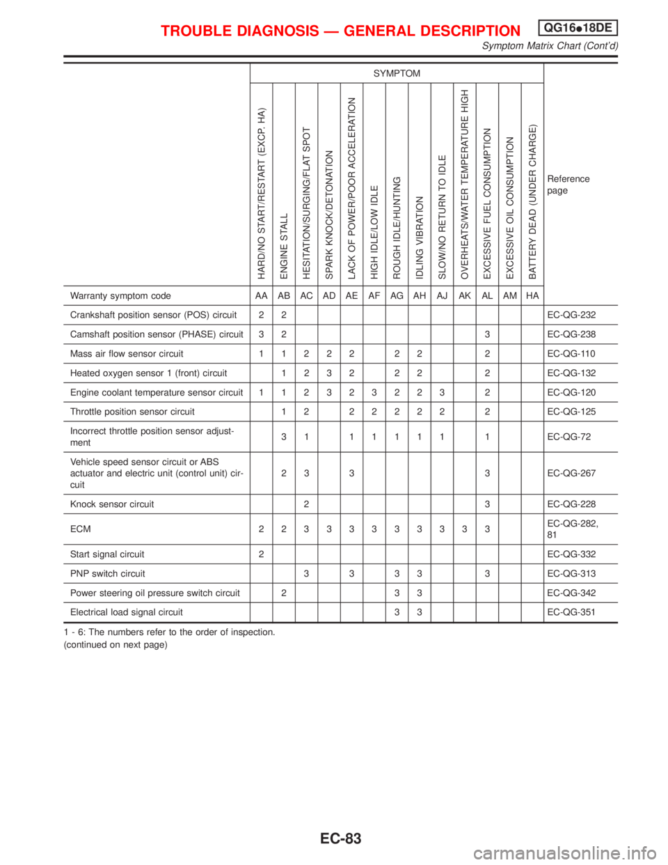
1 - 6: The numbers refer to the order of inspection.
(continued on next page)
TROUBLE DIAGNOSIS Ð GENERAL DESCRIPTIONQG16I18DE
Symptom Matrix Chart (Cont'd)
EC-83
Page 527 of 2267
SYMPTOM
Reference
page
HARD/NO START/RESTART (EXCP. HA)
ENGINE STALL
HESITATION/SURGING/FLAT SPOT
SPARK KNOCK/DETONATION
LACK OF POWER/POOR ACCELERATION
HIGH IDLE/LOW IDLE
ROUGH IDLE/HUNTING
IDLING VIBRATION
SLOW/NO RETURN TO IDLE
OVERHEATS/WATER TEMPERATURE HIGH
EXCESSIVE FUEL CONSUMPTION
EXCESSIVE OIL CONSUMPTION
BATTERY DEAD (UNDER CHARGE)
Warranty symptom code AA AB AC AD AE AF AG AH AJ AK AL AM HA
Engine Cylinder head
55555 55 5
EM section Cylinder head gasket 4 3
Cylinder block
66666 66 64 Piston
Piston ring
Connecting rod
Bearing
Crankshaft
Valve
mecha-
nismTiming chain
55555 55 5 EMsection Camshaft
Intake valve
3
Exhaust valve
Exhaust Exhaust manifold/Tube/Muffler/
Gasket
55555 55 5 FEsection
Three way catalyst
Lubrica-
tionOil pan/Oil strainer/Oil pump/Oil
filter/Oil gallery
55555 55 5MA, EM and
LC sections
Oil level (Low)/Filthy oil
LC section Cooling Radiator/Hose/Radiator filler cap
55555 55 45 Thermostat 5
Water pump
Water gallery
Cooling fan 5 EC-QG-289
Coolant level (low)/
Contaminated coolantMA section
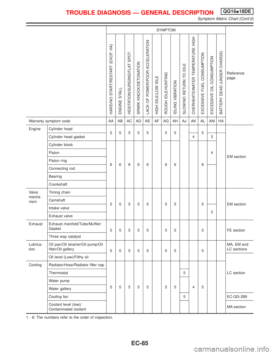
1 - 6: The numbers refer to the order of inspection.
TROUBLE DIAGNOSIS Ð GENERAL DESCRIPTIONQG16I18DE
Symptom Matrix Chart (Cont'd)
EC-85
Page 529 of 2267
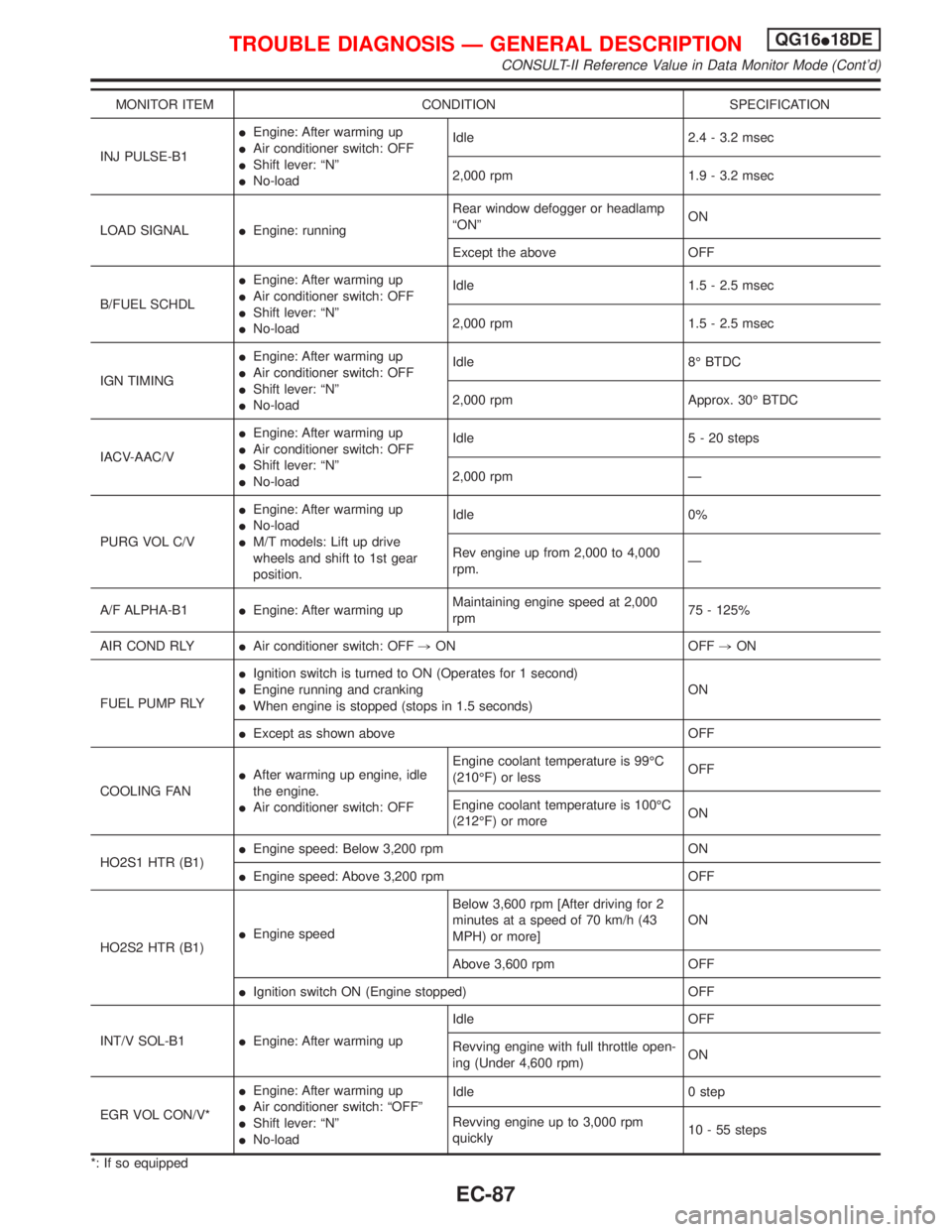
MONITOR ITEM CONDITION SPECIFICATION
INJ PULSE-B1IEngine: After warming up
IAir conditioner switch: OFF
IShift lever: ªNº
INo-loadIdle 2.4 - 3.2 msec
2,000 rpm 1.9 - 3.2 msec
LOAD SIGNALIEngine: runningRear window defogger or headlamp
ªONºON
Except the above OFF
B/FUEL SCHDLIEngine: After warming up
IAir conditioner switch: OFF
IShift lever: ªNº
INo-loadIdle 1.5 - 2.5 msec
2,000 rpm 1.5 - 2.5 msec
IGN TIMINGIEngine: After warming up
IAir conditioner switch: OFF
IShift lever: ªNº
INo-loadIdle 8É BTDC
2,000 rpm Approx. 30É BTDC
IACV-AAC/VIEngine: After warming up
IAir conditioner switch: OFF
IShift lever: ªNº
INo-loadIdle 5 - 20 steps
2,000 rpm Ð
PURG VOL C/VIEngine: After warming up
INo-load
IM/T models: Lift up drive
wheels and shift to 1st gear
position.Idle 0%
Rev engine up from 2,000 to 4,000
rpm.Ð
A/F ALPHA-B1IEngine: After warming upMaintaining engine speed at 2,000
rpm75 - 125%
AIR COND RLYIAir conditioner switch: OFF,ON OFF,ON
FUEL PUMP RLYIIgnition switch is turned to ON (Operates for 1 second)
IEngine running and cranking
IWhen engine is stopped (stops in 1.5 seconds)ON
IExcept as shown above OFF
COOLING FANIAfter warming up engine, idle
the engine.
IAir conditioner switch: OFFEngine coolant temperature is 99ÉC
(210ÉF) or lessOFF
Engine coolant temperature is 100ÉC
(212ÉF) or moreON
HO2S1 HTR (B1)IEngine speed: Below 3,200 rpm ON
IEngine speed: Above 3,200 rpm OFF
HO2S2 HTR (B1)IEngine speedBelow 3,600 rpm [After driving for 2
minutes at a speed of 70 km/h (43
MPH) or more]ON
Above 3,600 rpm OFF
IIgnition switch ON (Engine stopped) OFF
INT/V SOL-B1IEngine: After warming upIdle OFF
Revving engine with full throttle open-
ing (Under 4,600 rpm)ON
EGR VOL CON/V*IEngine: After warming up
IAir conditioner switch: ªOFFº
IShift lever: ªNº
INo-loadIdle 0 step
Revving engine up to 3,000 rpm
quickly10 - 55 steps
*: If so equipped
TROUBLE DIAGNOSIS Ð GENERAL DESCRIPTIONQG16I18DE
CONSULT-II Reference Value in Data Monitor Mode (Cont'd)
EC-87
Page 537 of 2267
![NISSAN PRIMERA 1999 Electronic Repair Manual TER-
MINAL
NO.WIRE
COLORITEM CONDITION DATA (DC Voltage)
66*
75W
WCamshaft position sen-
sor (PHASE)[Engine is running]
IWarm-up condition
IIdle speed2.0 - 3.0V
SEF977W
[Engine is running]
IEngine spe NISSAN PRIMERA 1999 Electronic Repair Manual TER-
MINAL
NO.WIRE
COLORITEM CONDITION DATA (DC Voltage)
66*
75W
WCamshaft position sen-
sor (PHASE)[Engine is running]
IWarm-up condition
IIdle speed2.0 - 3.0V
SEF977W
[Engine is running]
IEngine spe](/manual-img/5/57377/w960_57377-536.png)
TER-
MINAL
NO.WIRE
COLORITEM CONDITION DATA (DC Voltage)
66*
75W
WCamshaft position sen-
sor (PHASE)[Engine is running]
IWarm-up condition
IIdle speed2.0 - 3.0V
SEF977W
[Engine is running]
IEngine speed is 2,000 rpm2.0 - 3.0V
SEF978W
67 W/LPower supply for ECM
(Back-up)[Ignition switch ªOFFº]BATTERY VOLTAGE
(11 - 14V)
70 BR/YEngine coolant tem-
perature sensor[Engine is running]Approximately 0 - 4.8V
Output voltage varies with
engine coolant temperature
72* PUEGR temperature sen-
sor[Engine is running]
IWarm-up condition
IIdle speedLess than 4.5V
[Engine is running]
IWarm-up condition
IEGR system is operating0 - 1.0V
73 WMass air flow sensor
ground[Engine is running]
IWarm-up condition
IIdle speedApproximately 0V
74 R/LRefrigerant pressure
sensor[Engine is running]
IAir conditioner switch is ªONº
(Compressor operates)More than 1.5V
[Engine is running]
IAir conditioner switch is turned from ªONº to
ªOFFºVoltage is decreasing gradually
81 W Knock sensor[Engine is running]
IIdle speed1.0 - 4.0V
*: If so equipped
TROUBLE DIAGNOSIS Ð GENERAL DESCRIPTIONQG16I18DE
ECM Terminals and Reference Value (Cont'd)
EC-95