1999 NISSAN PRIMERA engine coolant
[x] Cancel search: engine coolantPage 444 of 2267
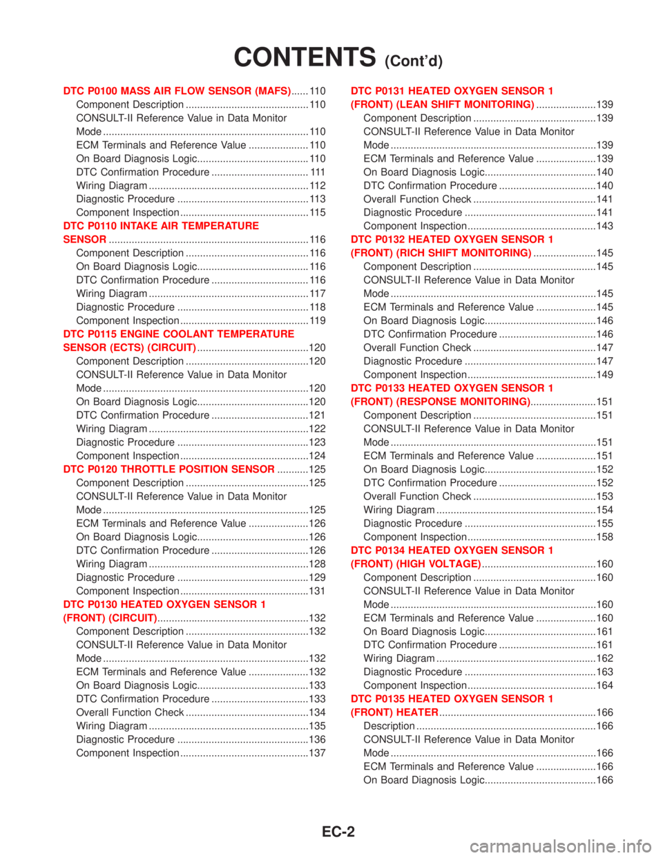
DTC P0100 MASS AIR FLOW SENSOR (MAFS)...... 110
Component Description ........................................... 110
CONSULT-II Reference Value in Data Monitor
Mode ........................................................................ 110
ECM Terminals and Reference Value ..................... 110
On Board Diagnosis Logic....................................... 110
DTC Confirmation Procedure .................................. 111
Wiring Diagram ........................................................ 112
Diagnostic Procedure .............................................. 113
Component Inspection ............................................. 115
DTC P0110 INTAKE AIR TEMPERATURE
SENSOR...................................................................... 116
Component Description ........................................... 116
On Board Diagnosis Logic....................................... 116
DTC Confirmation Procedure .................................. 116
Wiring Diagram ........................................................ 117
Diagnostic Procedure .............................................. 118
Component Inspection ............................................. 119
DTC P0115 ENGINE COOLANT TEMPERATURE
SENSOR (ECTS) (CIRCUIT).......................................120
Component Description ...........................................120
CONSULT-II Reference Value in Data Monitor
Mode ........................................................................120
On Board Diagnosis Logic.......................................120
DTC Confirmation Procedure ..................................121
Wiring Diagram ........................................................122
Diagnostic Procedure ..............................................123
Component Inspection .............................................124
DTC P0120 THROTTLE POSITION SENSOR...........125
Component Description ...........................................125
CONSULT-II Reference Value in Data Monitor
Mode ........................................................................125
ECM Terminals and Reference Value .....................126
On Board Diagnosis Logic.......................................126
DTC Confirmation Procedure ..................................126
Wiring Diagram ........................................................128
Diagnostic Procedure ..............................................129
Component Inspection .............................................131
DTC P0130 HEATED OXYGEN SENSOR 1
(FRONT) (CIRCUIT).....................................................132
Component Description ...........................................132
CONSULT-II Reference Value in Data Monitor
Mode ........................................................................132
ECM Terminals and Reference Value .....................132
On Board Diagnosis Logic.......................................133
DTC Confirmation Procedure ..................................133
Overall Function Check ...........................................134
Wiring Diagram ........................................................135
Diagnostic Procedure ..............................................136
Component Inspection .............................................137DTC P0131 HEATED OXYGEN SENSOR 1
(FRONT) (LEAN SHIFT MONITORING).....................139
Component Description ...........................................139
CONSULT-II Reference Value in Data Monitor
Mode ........................................................................139
ECM Terminals and Reference Value .....................139
On Board Diagnosis Logic.......................................140
DTC Confirmation Procedure ..................................140
Overall Function Check ...........................................141
Diagnostic Procedure ..............................................141
Component Inspection .............................................143
DTC P0132 HEATED OXYGEN SENSOR 1
(FRONT) (RICH SHIFT MONITORING)......................145
Component Description ...........................................145
CONSULT-II Reference Value in Data Monitor
Mode ........................................................................145
ECM Terminals and Reference Value .....................145
On Board Diagnosis Logic.......................................146
DTC Confirmation Procedure ..................................146
Overall Function Check ...........................................147
Diagnostic Procedure ..............................................147
Component Inspection .............................................149
DTC P0133 HEATED OXYGEN SENSOR 1
(FRONT) (RESPONSE MONITORING).......................151
Component Description ...........................................151
CONSULT-II Reference Value in Data Monitor
Mode ........................................................................151
ECM Terminals and Reference Value .....................151
On Board Diagnosis Logic.......................................152
DTC Confirmation Procedure ..................................152
Overall Function Check ...........................................153
Wiring Diagram ........................................................154
Diagnostic Procedure ..............................................155
Component Inspection .............................................158
DTC P0134 HEATED OXYGEN SENSOR 1
(FRONT) (HIGH VOLTAGE)........................................160
Component Description ...........................................160
CONSULT-II Reference Value in Data Monitor
Mode ........................................................................160
ECM Terminals and Reference Value .....................160
On Board Diagnosis Logic.......................................161
DTC Confirmation Procedure ..................................161
Wiring Diagram ........................................................162
Diagnostic Procedure ..............................................163
Component Inspection .............................................164
DTC P0135 HEATED OXYGEN SENSOR 1
(FRONT) HEATER.......................................................166
Description ...............................................................166
CONSULT-II Reference Value in Data Monitor
Mode ........................................................................166
ECM Terminals and Reference Value .....................166
On Board Diagnosis Logic.......................................166
CONTENTS(Cont'd)
EC-2
Page 447 of 2267
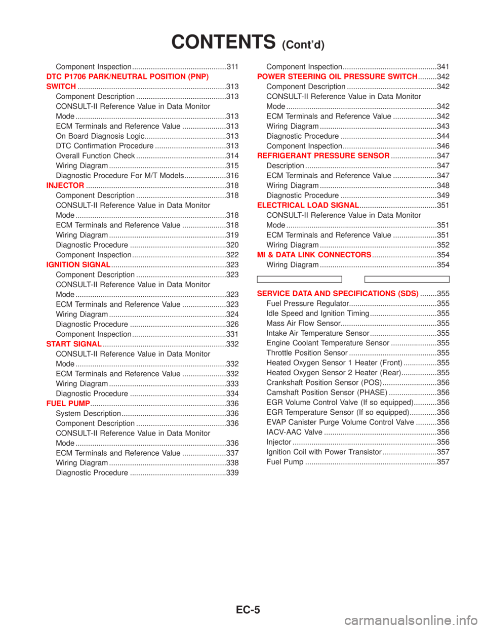
Component Inspection ............................................. 311
DTC P1706 PARK/NEUTRAL POSITION (PNP)
SWITCH.......................................................................313
Component Description ...........................................313
CONSULT-II Reference Value in Data Monitor
Mode ........................................................................313
ECM Terminals and Reference Value .....................313
On Board Diagnosis Logic.......................................313
DTC Confirmation Procedure ..................................313
Overall Function Check ...........................................314
Wiring Diagram ........................................................315
Diagnostic Procedure For M/T Models....................316
INJECTOR...................................................................318
Component Description ...........................................318
CONSULT-II Reference Value in Data Monitor
Mode ........................................................................318
ECM Terminals and Reference Value .....................318
Wiring Diagram ........................................................319
Diagnostic Procedure ..............................................320
Component Inspection .............................................322
IGNITION SIGNAL.......................................................323
Component Description ...........................................323
CONSULT-II Reference Value in Data Monitor
Mode ........................................................................323
ECM Terminals and Reference Value .....................323
Wiring Diagram ........................................................324
Diagnostic Procedure ..............................................326
Component Inspection .............................................331
START SIGNAL...........................................................332
CONSULT-II Reference Value in Data Monitor
Mode ........................................................................332
ECM Terminals and Reference Value .....................332
Wiring Diagram ........................................................333
Diagnostic Procedure ..............................................334
FUEL PUMP.................................................................336
System Description ..................................................336
Component Description ...........................................336
CONSULT-II Reference Value in Data Monitor
Mode ........................................................................336
ECM Terminals and Reference Value .....................337
Wiring Diagram ........................................................338
Diagnostic Procedure ..............................................339Component Inspection .............................................341
POWER STEERING OIL PRESSURE SWITCH.........342
Component Description ...........................................342
CONSULT-II Reference Value in Data Monitor
Mode ........................................................................342
ECM Terminals and Reference Value .....................342
Wiring Diagram ........................................................343
Diagnostic Procedure ..............................................344
Component Inspection .............................................346
REFRIGERANT PRESSURE SENSOR......................347
Description ...............................................................347
ECM Terminals and Reference Value .....................347
Wiring Diagram ........................................................348
Diagnostic Procedure ..............................................349
ELECTRICAL LOAD SIGNAL.....................................351
CONSULT-II Reference Value in Data Monitor
Mode ........................................................................351
ECM Terminals and Reference Value .....................351
Wiring Diagram ........................................................352
MI & DATA LINK CONNECTORS...............................354
Wiring Diagram ........................................................354
SERVICE DATA AND SPECIFICATIONS (SDS)........355
Fuel Pressure Regulator..........................................355
Idle Speed and Ignition Timing ................................355
Mass Air Flow Sensor..............................................355
Intake Air Temperature Sensor ................................355
Engine Coolant Temperature Sensor ......................355
Throttle Position Sensor ..........................................355
Heated Oxygen Sensor 1 Heater (Front) ................355
Heated Oxygen Sensor 2 Heater (Rear).................355
Crankshaft Position Sensor (POS) ..........................356
Camshaft Position Sensor (PHASE) .......................356
EGR Volume Control Valve (If so equipped)...........356
EGR Temperature Sensor (If so equipped).............356
EVAP Canister Purge Volume Control Valve ..........356
IACV-AAC Valve ......................................................356
Injector .....................................................................356
Ignition Coil with Power Transistor ..........................357
Fuel Pump ...............................................................357
CONTENTS(Cont'd)
EC-5
Page 449 of 2267
Items
(CONSULT-II screen terms)DTC*5
Reference page
CONSULT-II
GST*2ECM*1
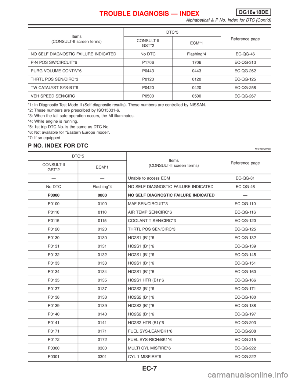
NO SELF DIAGNOSTIC FAILURE INDICATED No DTC Flashing*4 EC-QG-46
P-N POS SW/CIRCUIT*6 P1706 1706 EC-QG-313
PURG VOLUME CONT/V*6 P0443 0443 EC-QG-262
THRTL POS SEN/CIRC*3 P0120 0120 EC-QG-125
TW CATALYST SYS-B1*6 P0420 0420 EC-QG-258
VEH SPEED SEN/CIRC P0500 0500 EC-QG-267
*1: In Diagnostic Test Mode II (Self-diagnostic results). These numbers are controlled by NISSAN.
*2: These numbers are prescribed by ISO15031-6.
*3: When the fail-safe operation occurs, the MI illuminates.
*4: While engine is running.
*5: 1st trip DTC No. is the same as DTC No.
*6: Not available for ªEastern Europe modelº.
*7: If so equipped
P NO. INDEX FOR DTCNCEC0001S02
DTC*5
Items
(CONSULT-II screen terms)Reference page
CONSULT-II
GST*2ECM*1
Ð Ð Unable to access ECM EC-QG-81
No DTC Flashing*4 NO SELF DIAGNOSTIC FAILURE INDICATED EC-QG-46
P0000 0000 NO SELF DIAGNOSTIC FAILURE INDICATED Ð
P0100 0100 MAF SEN/CIRCUIT*3 EC-QG-110
P0110 0110 AIR TEMP SEN/CIRC*6 EC-QG-116
P0115 0115 COOLANT T SEN/CIRC*3 EC-QG-120
P0120 0120 THRTL POS SEN/CIRC*3 EC-QG-125
P0130 0130 HO2S1 (B1)*6 EC-QG-132
P0131 0131 HO2S1 (B1)*6 EC-QG-139
P0132 0132 HO2S1 (B1)*6 EC-QG-145
P0133 0133 HO2S1 (B1)*6 EC-QG-151
P0134 0134 HO2S1 (B1)*6 EC-QG-160
P0135 0135 HO2S1 HTR (B1)*6 EC-QG-166
P0137 0137 HO2S2 (B1)*6 EC-QG-171
P0138 0138 HO2S2 (B1)*6 EC-QG-180
P0139 0139 HO2S2 (B1)*6 EC-QG-188
P0140 0140 HO2S2 (B1)*6 EC-QG-197
P0141 0141 HO2S2 HTR (B1)*6 EC-QG-203
P0171 0171 FUEL SYS-LEAN/BK1*6 EC-QG-208
P0172 0172 FUEL SYS-RICH/BK1*6 EC-QG-215
P0300 0300 MULTI CYL MISFIRE*6 EC-QG-222
P0301 0301 CYL 1 MISFIRE*6 EC-QG-222
TROUBLE DIAGNOSIS Ð INDEXQG16I18DE
Alphabetical & P No. Index for DTC (Cont'd)
EC-7
Page 462 of 2267
System ChartNCEC0013
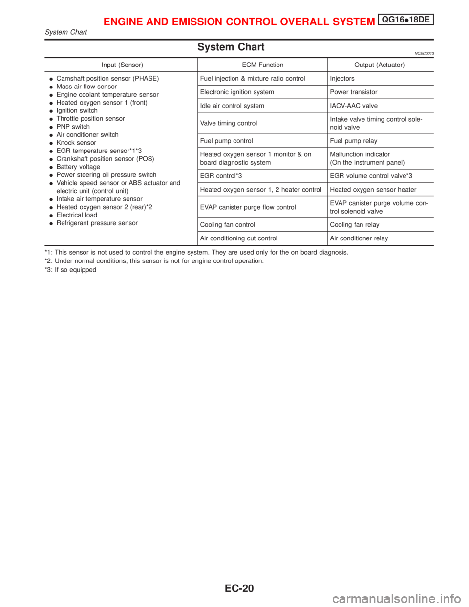
Input (Sensor) ECM Function Output (Actuator)
ICamshaft position sensor (PHASE)
IMass air flow sensor
IEngine coolant temperature sensor
IHeated oxygen sensor 1 (front)
IIgnition switch
IThrottle position sensor
IPNP switch
IAir conditioner switch
IKnock sensor
IEGR temperature sensor*1*3
ICrankshaft position sensor (POS)
IBattery voltage
IPower steering oil pressure switch
IVehicle speed sensor or ABS actuator and
electric unit (control unit)
IIntake air temperature sensor
IHeated oxygen sensor 2 (rear)*2
IElectrical load
IRefrigerant pressure sensorFuel injection & mixture ratio control Injectors
Electronic ignition system Power transistor
Idle air control system IACV-AAC valve
Valve timing controlIntake valve timing control sole-
noid valve
Fuel pump control Fuel pump relay
Heated oxygen sensor 1 monitor & on
board diagnostic systemMalfunction indicator
(On the instrument panel)
EGR control*3 EGR volume control valve*3
Heated oxygen sensor 1, 2 heater control Heated oxygen sensor heater
EVAP canister purge flow controlEVAP canister purge volume con-
trol solenoid valve
Cooling fan control Cooling fan relay
Air conditioning cut control Air conditioner relay
*1: This sensor is not used to control the engine system. They are used only for the on board diagnosis.
*2: Under normal conditions, this sensor is not for engine control operation.
*3: If so equipped
ENGINE AND EMISSION CONTROL OVERALL SYSTEMQG16I18DE
System Chart
EC-20
Page 463 of 2267
Multiport Fuel Injection (MFI) System
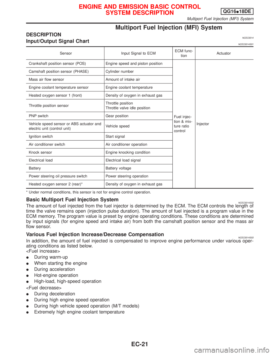
DESCRIPTIONNCEC0014Input/Output Signal ChartNCEC0014S01
Sensor Input Signal to ECMECM func-
tionActuator
Crankshaft position sensor (POS) Engine speed and piston position
Fuel injec-
tion & mix-
ture ratio
controlInjector Camshaft position sensor (PHASE) Cylinder number
Mass air flow sensor Amount of intake air
Engine coolant temperature sensor Engine coolant temperature
Heated oxygen sensor 1 (front) Density of oxygen in exhaust gas
Throttle position sensorThrottle position
Throttle valve idle position
PNP switch Gear position
Vehicle speed sensor or ABS actuator and
electric unit (control unit)Vehicle speed
Ignition switch Start signal
Air conditioner switch Air conditioner operation
Knock sensor Engine knocking condition
Electrical load Electrical load signal
Battery Battery voltage
Power steering oil pressure switch Power steering operation
Heated oxygen sensor 2 (rear)* Density of oxygen in exhaust gas
* Under normal conditions, this sensor is not for engine control operation.
Basic Multiport Fuel Injection SystemNCEC0014S02The amount of fuel injected from the fuel injector is determined by the ECM. The ECM controls the length of
time the valve remains open (injection pulse duration). The amount of fuel injected is a program value in the
ECM memory. The program value is preset by engine operating conditions. These conditions are determined
by input signals (for engine speed and intake air) from both the camshaft position sensor and the mass air
flow sensor.
Various Fuel Injection Increase/Decrease CompensationNCEC0014S03In addition, the amount of fuel injected is compensated to improve engine performance under various oper-
ating conditions as listed below.
IDuring warm-up
IWhen starting the engine
IDuring acceleration
IHot-engine operation
IHigh-load, high-speed operation
IDuring deceleration
IDuring high engine speed operation
IDuring high vehicle speed operation (M/T models)
IExtremely high engine coolant temperature
ENGINE AND EMISSION BASIC CONTROL
SYSTEM DESCRIPTIONQG16I18DE
Multiport Fuel Injection (MFI) System
EC-21
Page 464 of 2267
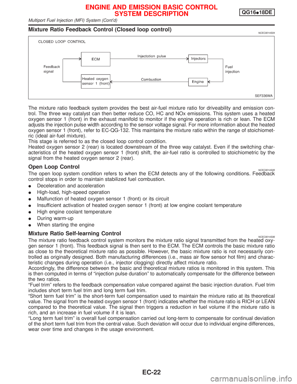
Mixture Ratio Feedback Control (Closed loop control)NCEC0014S04
The mixture ratio feedback system provides the best air-fuel mixture ratio for driveability and emission con-
trol. The three way catalyst can then better reduce CO, HC and NOx emissions. This system uses a heated
oxygen sensor 1 (front) in the exhaust manifold to monitor if the engine operation is rich or lean. The ECM
adjusts the injection pulse width according to the sensor voltage signal. For more information about the heated
oxygen sensor 1 (front), refer to EC-QG-132. This maintains the mixture ratio within the range of stoichiomet-
ric (ideal air-fuel mixture).
This stage is referred to as the closed loop control condition.
Heated oxygen sensor 2 (rear) is located downstream of the three way catalyst. Even if the switching char-
acteristics of the heated oxygen sensor 1 (front) shift, the air-fuel ratio is controlled to stoichiometric by the
signal from the heated oxygen sensor 2 (rear).
Open Loop ControlNCEC0014S05The open loop system condition refers to when the ECM detects any of the following conditions. Feedback
control stops in order to maintain stabilized fuel combustion.
IDeceleration and acceleration
IHigh-load, high-speed operation
IMalfunction of heated oxygen sensor 1 (front) or its circuit
IInsufficient activation of heated oxygen sensor 1 (front) at low engine coolant temperature
IHigh engine coolant temperature
IDuring warm-up
IWhen starting the engine
Mixture Ratio Self-learning ControlNCEC0014S06The mixture ratio feedback control system monitors the mixture ratio signal transmitted from the heated oxy-
gen sensor 1 (front). This feedback signal is then sent to the ECM. The ECM controls the basic mixture ratio
as close to the theoretical mixture ratio as possible. However, the basic mixture ratio is not necessarily con-
trolled as originally designed. Both manufacturing differences (i.e., mass air flow sensor hot film) and charac-
teristic changes during operation (i.e., injector clogging) directly affect mixture ratio.
Accordingly, the difference between the basic and theoretical mixture ratios is monitored in this system. This
is then computed in terms of ªinjection pulse durationº to automatically compensate for the difference between
the two ratios.
ªFuel trimº refers to the feedback compensation value compared against the basic injection duration. Fuel trim
includes short term fuel trim and long term fuel trim.
ªShort term fuel trimº is the short-term fuel compensation used to maintain the mixture ratio at its theoretical
value. The signal from the heated oxygen sensor 1 (front) indicates whether the mixture ratio is RICH or LEAN
compared to the theoretical value. The signal then triggers a reduction in fuel volume if the mixture ratio is
rich, and an increase in fuel volume if it is lean.
ªLong term fuel trimº is overall fuel compensation carried out long-term to compensate for continual deviation
of the short term fuel trim from the central value. Such deviation will occur due to individual engine differences,
wear over time and changes in the usage environment.
SEF336WA
ENGINE AND EMISSION BASIC CONTROL
SYSTEM DESCRIPTIONQG16I18DE
Multiport Fuel Injection (MFI) System (Cont'd)
EC-22
Page 465 of 2267
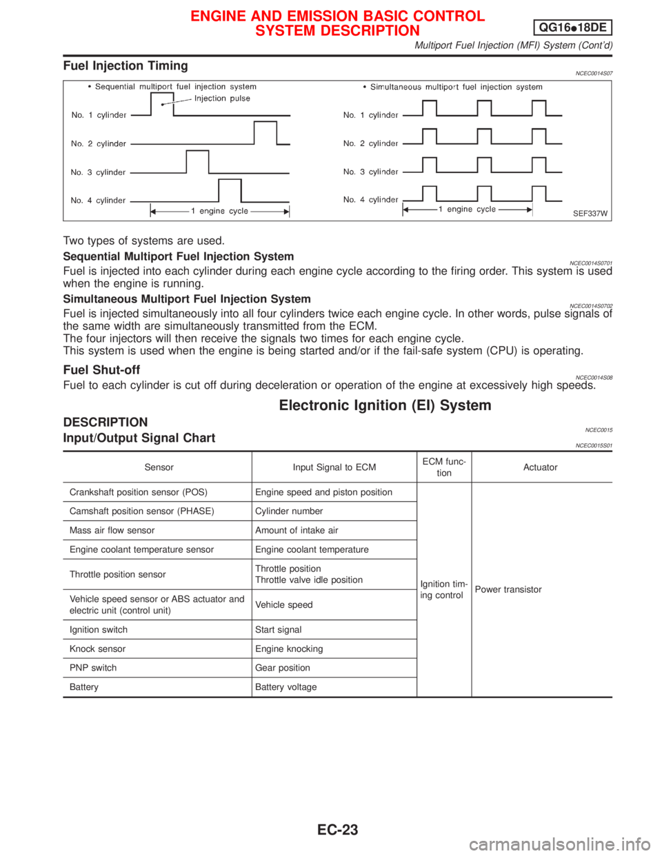
Fuel Injection TimingNCEC0014S07
Two types of systems are used.
Sequential Multiport Fuel Injection System
NCEC0014S0701Fuel is injected into each cylinder during each engine cycle according to the firing order. This system is used
when the engine is running.
Simultaneous Multiport Fuel Injection System
NCEC0014S0702Fuel is injected simultaneously into all four cylinders twice each engine cycle. In other words, pulse signals of
the same width are simultaneously transmitted from the ECM.
The four injectors will then receive the signals two times for each engine cycle.
This system is used when the engine is being started and/or if the fail-safe system (CPU) is operating.
Fuel Shut-offNCEC0014S08Fuel to each cylinder is cut off during deceleration or operation of the engine at excessively high speeds.
Electronic Ignition (EI) System
DESCRIPTIONNCEC0015Input/Output Signal ChartNCEC0015S01
Sensor Input Signal to ECMECM func-
tionActuator
Crankshaft position sensor (POS) Engine speed and piston position
Ignition tim-
ing controlPower transistor Camshaft position sensor (PHASE) Cylinder number
Mass air flow sensor Amount of intake air
Engine coolant temperature sensor Engine coolant temperature
Throttle position sensorThrottle position
Throttle valve idle position
Vehicle speed sensor or ABS actuator and
electric unit (control unit)Vehicle speed
Ignition switch Start signal
Knock sensor Engine knocking
PNP switch Gear position
Battery Battery voltage
SEF337W
ENGINE AND EMISSION BASIC CONTROL
SYSTEM DESCRIPTIONQG16I18DE
Multiport Fuel Injection (MFI) System (Cont'd)
EC-23
Page 466 of 2267
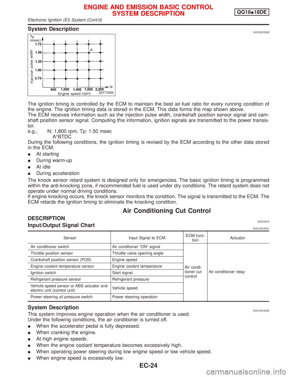
System DescriptionNCEC0015S02
The ignition timing is controlled by the ECM to maintain the best air-fuel ratio for every running condition of
the engine. The ignition timing data is stored in the ECM. This data forms the map shown above.
The ECM receives information such as the injection pulse width, crankshaft position sensor signal and cam-
shaft position sensor signal. Computing this information, ignition signals are transmitted to the power transis-
tor.
e.g., N: 1,800 rpm, Tp: 1.50 msec
AÉBTDC
During the following conditions, the ignition timing is revised by the ECM according to the other data stored
in the ECM.
IAt starting
IDuring warm-up
IAt idle
IDuring acceleration
The knock sensor retard system is designed only for emergencies. The basic ignition timing is programmed
within the anti-knocking zone, if recommended fuel is used under dry conditions. The retard system does not
operate under normal driving conditions.
If engine knocking occurs, the knock sensor monitors the condition. The signal is transmitted to the ECM. The
ECM retards the ignition timing to eliminate the knocking condition.
Air Conditioning Cut Control
DESCRIPTIONNCEC0016Input/Output Signal ChartNCEC0016S01
Sensor Input Signal to ECMECM func-
tionActuator
Air conditioner switch Air conditioner ªONº signal
Air condi-
tioner cut
controlAir conditioner relay Throttle position sensor Throttle valve opening angle
Crankshaft position sensor (POS) Engine speed
Engine coolant temperature sensor Engine coolant temperature
Ignition switch Start signal
Refrigerant pressure sensor Refrigerant pressure
Vehicle speed sensor or ABS actuator and
electric unit (control unit)Vehicle speed
Power steering oil pressure switch Power steering operation
System DescriptionNCEC0016S02This system improves engine operation when the air conditioner is used.
Under the following conditions, the air conditioner is turned off.
IWhen the accelerator pedal is fully depressed.
IWhen cranking the engine.
IAt high engine speeds.
IWhen the engine coolant temperature becomes excessively high.
IWhen operating power steering during low engine speed or low vehicle speed.
IWhen engine speed is excessively low.
SEF742M
ENGINE AND EMISSION BASIC CONTROL
SYSTEM DESCRIPTIONQG16I18DE
Electronic Ignition (EI) System (Cont'd)
EC-24