1999 NISSAN PRIMERA engine coolant
[x] Cancel search: engine coolantPage 739 of 2267
12 CHECK RADIATOR CAP
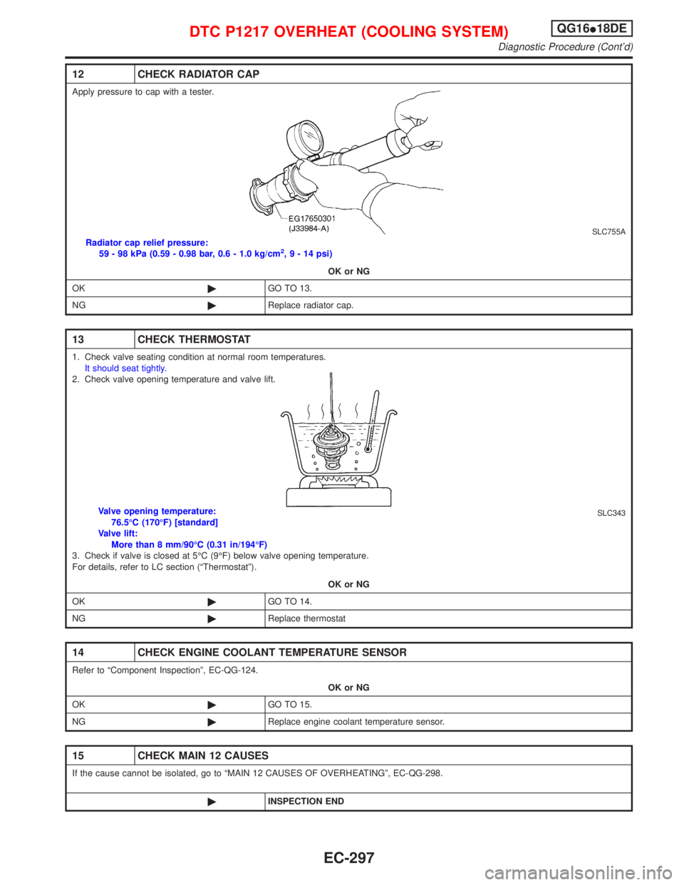
Apply pressure to cap with a tester.
SLC755ARadiator cap relief pressure:
59 - 98 kPa (0.59 - 0.98 bar, 0.6 - 1.0 kg/cm2,9-14psi)
OK or NG
OK©GO TO 13.
NG©Replace radiator cap.
13 CHECK THERMOSTAT
1. Check valve seating condition at normal room temperatures.
It should seat tightly.
2. Check valve opening temperature and valve lift.
SLC343Valve opening temperature:
76.5ÉC (170ÉF) [standard]
Valve lift:
More than 8 mm/90ÉC (0.31 in/194ÉF)
3. Check if valve is closed at 5ÉC (9ÉF) below valve opening temperature.
For details, refer to LC section (ªThermostatº).
OK or NG
OK©GO TO 14.
NG©Replace thermostat
14 CHECK ENGINE COOLANT TEMPERATURE SENSOR
Refer to ªComponent Inspectionº, EC-QG-124.
OK or NG
OK©GO TO 15.
NG©Replace engine coolant temperature sensor.
15 CHECK MAIN 12 CAUSES
If the cause cannot be isolated, go to ªMAIN 12 CAUSES OF OVERHEATINGº, EC-QG-298.
©INSPECTION END
DTC P1217 OVERHEAT (COOLING SYSTEM)QG16I18DE
Diagnostic Procedure (Cont'd)
EC-297
Page 740 of 2267
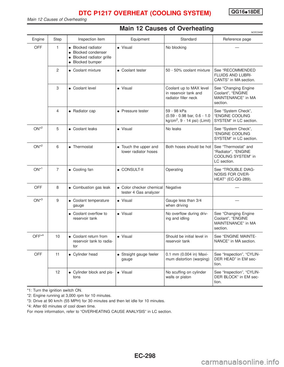
Main 12 Causes of OverheatingNCEC0492
Engine Step Inspection item Equipment Standard Reference page
OFF 1IBlocked radiator
IBlocked condenser
IBlocked radiator grille
IBlocked bumperIVisual No blocking Ð
2ICoolant mixtureICoolant tester 50 - 50% coolant mixture See ªRECOMMENDED
FLUIDS AND LUBRI-
CANTSº in MA section.
3ICoolant levelIVisual Coolant up to MAX level
in reservoir tank and
radiator filler neckSee ªChanging Engine
Coolantº, ªENGINE
MAINTENANCEº in MA
section.
4IRadiator capIPressure tester 59 - 98 kPa
(0.59 - 0.98 bar, 0.6 - 1.0
kg/cm
2,9-14psi) (Limit)See ªSystem Checkº,
ªENGINE COOLING
SYSTEMº in LC section.
ON*
25ICoolant leaksIVisual No leaks See ªSystem Checkº,
ªENGINE COOLING
SYSTEMº in LC section.
ON*
26IThermostatITouch the upper and
lower radiator hosesBoth hoses should be hot See ªThermostatº and
ªRadiatorº, ªENGINE
COOLING SYSTEMº in
LC section.
ON*
17ICooling fanICONSULT-II Operating See ªTROUBLE DIAG-
NOSIS FOR OVER-
HEATº (EC-QG-289).
OFF 8ICombustion gas leakIColor checker chemical
tester 4 Gas analyzerNegative Ð
ON*
39ICoolant temperature
gaugeIVisual Gauge less than 3/4
when drivingÐ
ICoolant overflow to
reservoir tankIVisual No overflow during driv-
ing and idlingSee ªChanging Engine
Coolantº, ªENGINE
MAINTENANCEº in MA
section.
OFF*
410ICoolant return from
reservoir tank to radia-
torIVisual Should be initial level in
reservoir tankSee ªENGINE MAINTE-
NANCEº in MA section.
OFF 11ICylinder headIStraight gauge feeler
gauge0.1 mm (0.004 in) Maxi-
mum distortion (warping)See ªInspectionº, ªCYLIN-
DER HEADº in EM sec-
tion.
12ICylinder block and pis-
tonsIVisual No scuffing on cylinder
walls or pistonSee ªInspectionº, ªCYLIN-
DER BLOCKº in EM sec-
tion.
*1: Turn the ignition switch ON.
*2: Engine running at 3,000 rpm for 10 minutes.
*3: Drive at 90 km/h (55 MPH) for 30 minutes and then let idle for 10 minutes.
*4: After 60 minutes of cool down time.
For more information, refer to ªOVERHEATING CAUSE ANALYSISº in LC section.
DTC P1217 OVERHEAT (COOLING SYSTEM)QG16I18DE
Main 12 Causes of Overheating
EC-298
Page 743 of 2267
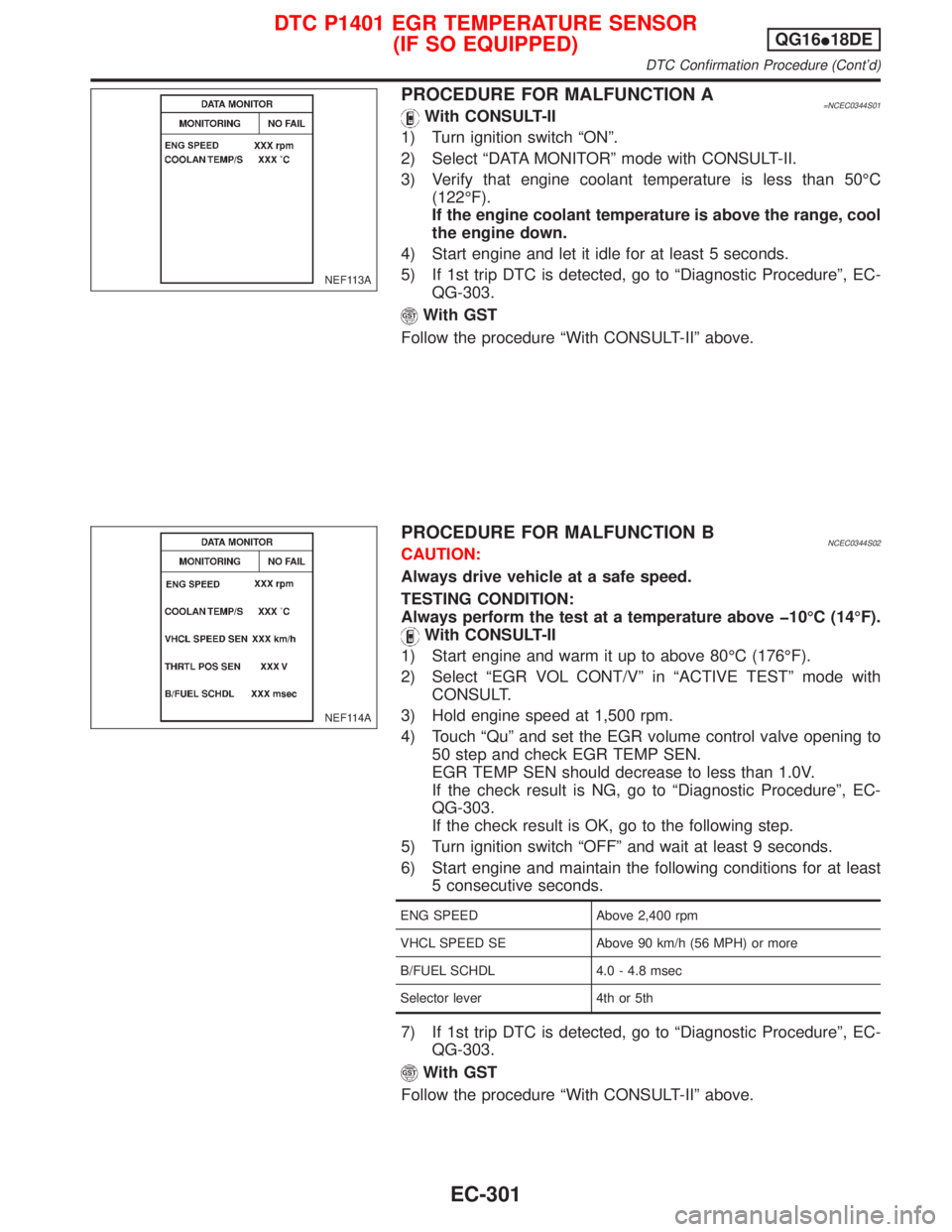
PROCEDURE FOR MALFUNCTION A=NCEC0344S01With CONSULT-II
1) Turn ignition switch ªONº.
2) Select ªDATA MONITORº mode with CONSULT-II.
3) Verify that engine coolant temperature is less than 50ÉC
(122ÉF).
If the engine coolant temperature is above the range, cool
the engine down.
4) Start engine and let it idle for at least 5 seconds.
5) If 1st trip DTC is detected, go to ªDiagnostic Procedureº, EC-
QG-303.
With GST
Follow the procedure ªWith CONSULT-IIº above.
PROCEDURE FOR MALFUNCTION BNCEC0344S02CAUTION:
Always drive vehicle at a safe speed.
TESTING CONDITION:
Always perform the test at a temperature above þ10ÉC (14ÉF).
With CONSULT-II
1) Start engine and warm it up to above 80ÉC (176ÉF).
2) Select ªEGR VOL CONT/Vº in ªACTIVE TESTº mode with
CONSULT.
3) Hold engine speed at 1,500 rpm.
4) Touch ªQuº and set the EGR volume control valve opening to
50 step and check EGR TEMP SEN.
EGR TEMP SEN should decrease to less than 1.0V.
If the check result is NG, go to ªDiagnostic Procedureº, EC-
QG-303.
If the check result is OK, go to the following step.
5) Turn ignition switch ªOFFº and wait at least 9 seconds.
6) Start engine and maintain the following conditions for at least
5 consecutive seconds.
ENG SPEED Above 2,400 rpm
VHCL SPEED SE Above 90 km/h (56 MPH) or more
B/FUEL SCHDL 4.0 - 4.8 msec
Selector lever 4th or 5th
7) If 1st trip DTC is detected, go to ªDiagnostic Procedureº, EC-
QG-303.
With GST
Follow the procedure ªWith CONSULT-IIº above.
NEF113A
NEF114A
DTC P1401 EGR TEMPERATURE SENSOR
(IF SO EQUIPPED)QG16I18DE
DTC Confirmation Procedure (Cont'd)
EC-301
Page 747 of 2267
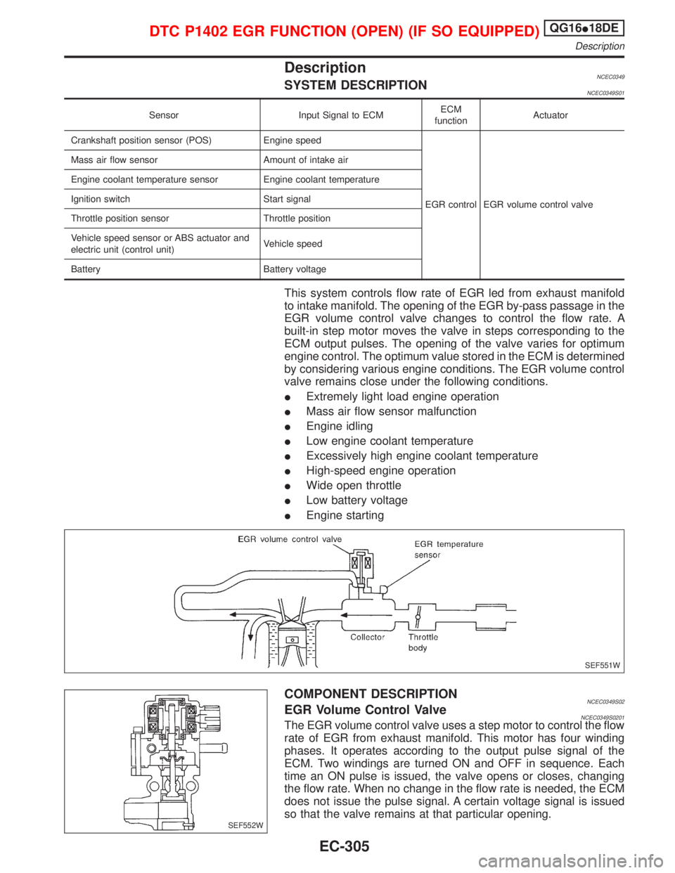
DescriptionNCEC0349SYSTEM DESCRIPTIONNCEC0349S01
Sensor Input Signal to ECMECM
functionActuator
Crankshaft position sensor (POS) Engine speed
EGR control EGR volume control valve Mass air flow sensor Amount of intake air
Engine coolant temperature sensor Engine coolant temperature
Ignition switch Start signal
Throttle position sensor Throttle position
Vehicle speed sensor or ABS actuator and
electric unit (control unit)Vehicle speed
Battery Battery voltage
This system controls flow rate of EGR led from exhaust manifold
to intake manifold. The opening of the EGR by-pass passage in the
EGR volume control valve changes to control the flow rate. A
built-in step motor moves the valve in steps corresponding to the
ECM output pulses. The opening of the valve varies for optimum
engine control. The optimum value stored in the ECM is determined
by considering various engine conditions. The EGR volume control
valve remains close under the following conditions.
IExtremely light load engine operation
IMass air flow sensor malfunction
IEngine idling
ILow engine coolant temperature
IExcessively high engine coolant temperature
IHigh-speed engine operation
IWide open throttle
ILow battery voltage
IEngine starting
COMPONENT DESCRIPTIONNCEC0349S02EGR Volume Control ValveNCEC0349S0201The EGR volume control valve uses a step motor to control the flow
rate of EGR from exhaust manifold. This motor has four winding
phases. It operates according to the output pulse signal of the
ECM. Two windings are turned ON and OFF in sequence. Each
time an ON pulse is issued, the valve opens or closes, changing
the flow rate. When no change in the flow rate is needed, the ECM
does not issue the pulse signal. A certain voltage signal is issued
so that the valve remains at that particular opening.
SEF551W
SEF552W
DTC P1402 EGR FUNCTION (OPEN) (IF SO EQUIPPED)QG16I18DE
Description
EC-305
Page 749 of 2267
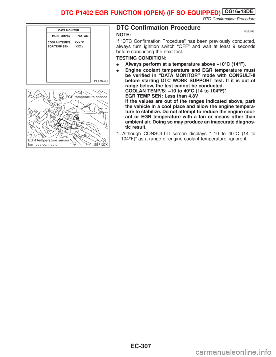
DTC Confirmation ProcedureNCEC0351NOTE:
If ªDTC Confirmation Procedureº has been previously conducted,
always turn ignition switch ªOFFº and wait at least 9 seconds
before conducting the next test.
TESTING CONDITION:
IAlways perform at a temperature above þ10ÉC (14ÉF).
IEngine coolant temperature and EGR temperature must
be verified in ªDATA MONITORº mode with CONSULT-II
before starting DTC WORK SUPPORT test. If it is out of
range below, the test cannot be conducted.
COOLAN TEMP/S: þ10 to 40ÉC (14 to 104ÉF)*
EGR TEMP SEN: Less than 4.8V
If the values are out of the ranges indicated above, park
the vehicle in a cool place and allow the engine tempera-
ture to stabilize. Do not attempt to reduce the engine cool-
ant or EGR temperature with a fan or means other than
ambient air. Doing so may produce an inaccurate diagnos-
tic result.
*: Although CONSULT-II screen displays ªþ10 to 40ÉC (14 to
104ÉF)º as a range of engine coolant temperature, ignore it.
PEF347U
SEF127X
DTC P1402 EGR FUNCTION (OPEN) (IF SO EQUIPPED)QG16I18DE
DTC Confirmation Procedure
EC-307
Page 750 of 2267
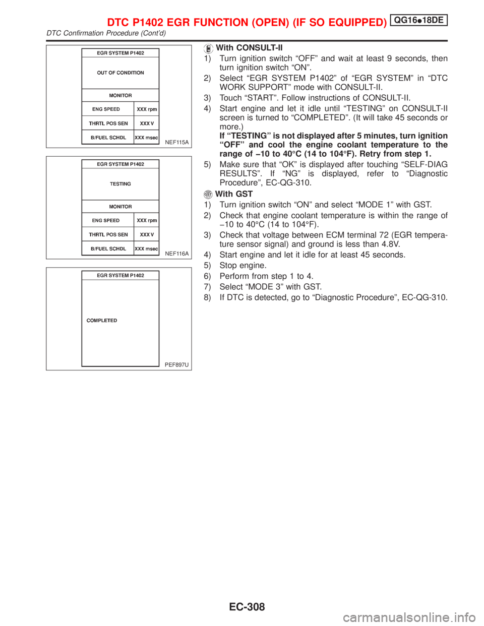
With CONSULT-II
1) Turn ignition switch ªOFFº and wait at least 9 seconds, then
turn ignition switch ªONº.
2) Select ªEGR SYSTEM P1402º of ªEGR SYSTEMº in ªDTC
WORK SUPPORTº mode with CONSULT-II.
3) Touch ªSTARTº. Follow instructions of CONSULT-II.
4) Start engine and let it idle until ªTESTINGº on CONSULT-II
screen is turned to ªCOMPLETEDº. (It will take 45 seconds or
more.)
If ªTESTINGº is not displayed after 5 minutes, turn ignition
ªOFFº and cool the engine coolant temperature to the
range of þ10 to 40ÉC (14 to 104ÉF). Retry from step 1.
5) Make sure that ªOKº is displayed after touching ªSELF-DIAG
RESULTSº. If ªNGº is displayed, refer to ªDiagnostic
Procedureº, EC-QG-310.
With GST
1) Turn ignition switch ªONº and select ªMODE 1º with GST.
2) Check that engine coolant temperature is within the range of
þ10 to 40ÉC (14 to 104ÉF).
3) Check that voltage between ECM terminal 72 (EGR tempera-
ture sensor signal) and ground is less than 4.8V.
4) Start engine and let it idle for at least 45 seconds.
5) Stop engine.
6) Perform from step 1 to 4.
7) Select ªMODE 3º with GST.
8) If DTC is detected, go to ªDiagnostic Procedureº, EC-QG-310.
NEF115A
NEF116A
PEF897U
DTC P1402 EGR FUNCTION (OPEN) (IF SO EQUIPPED)QG16I18DE
DTC Confirmation Procedure (Cont'd)
EC-308
Page 797 of 2267
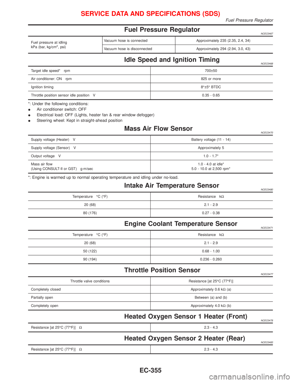
Fuel Pressure RegulatorNCEC0467
Fuel pressure at idling
kPa (bar, kg/cm2, psi)Vacuum hose is connected Approximately 235 (2.35, 2.4, 34)
Vacuum hose is disconnected Approximately 294 (2.94, 3.0, 43)
Idle Speed and Ignition TimingNCEC0468
Target idle speed* rpm700 50
Air conditioner: ON rpm825 or more
Ignition timing8É 5É BTDC
Throttle position sensor idle position V 0.35 - 0.65
*: Under the following conditions:
IAir conditioner switch: OFF
IElectrical load: OFF (Lights, heater fan & rear window defogger)
ISteering wheel: Kept in straight-ahead position
Mass Air Flow SensorNCEC0470
Supply voltage (Heater) VBattery voltage (11 - 14)
Supply voltage (Sensor) VApproximately 5
Output voltage V1.0 - 1.7*
Mass air flow
(Using CONSULT-II or GST) g×m/sec1.0 - 4.0 at idle*
5.0 - 10.0 at 2,500 rpm*
*: Engine is warmed up to normal operating temperature and idling under no-load.
Intake Air Temperature SensorNCEC0480
Temperature ÉC (ÉF) Resistance kW
20 (68) 2.1 - 2.9
80 (176) 0.27 - 0.38
Engine Coolant Temperature SensorNCEC0471
Temperature ÉC (ÉF) Resistance kW
20 (68) 2.1 - 2.9
50 (122) 0.68 - 1.00
90 (194) 0.236 - 0.260
Throttle Position SensorNCEC0477
Throttle valve conditions Resistance [at 25ÉC (77ÉF)]
Completely closedApproximately 0.6 kW(a)
Partially openBetween (a) and (b)
Completely openApproximately 4.0 kW(b)
Heated Oxygen Sensor 1 Heater (Front)NCEC0478
Resistance [at 25ÉC (77ÉF)]W2.3 - 4.3
Heated Oxygen Sensor 2 Heater (Rear)NCEC0483
Resistance [at 25ÉC (77ÉF)]W2.3 - 4.3
SERVICE DATA AND SPECIFICATIONS (SDS)
Fuel Pressure Regulator
EC-355
Page 802 of 2267
DTC P0100 MASS AIR FLOW SENSOR (MAFS)......120
Component Description ...........................................120
CONSULT-II Reference Value in Data Monitor
Mode ........................................................................120
ECM Terminals and Reference Value .....................120
On Board Diagnosis Logic.......................................120
DTC Confirmation Procedure ..................................121
Wiring Diagram ........................................................122
Diagnostic Procedure ..............................................123
Component Inspection .............................................126
DTC P0110 INTAKE AIR TEMPERATURE
SENSOR......................................................................127
Component Description ...........................................127
On Board Diagnosis Logic.......................................127
DTC Confirmation Procedure ..................................127
Wiring Diagram ........................................................128
Diagnostic Procedure ..............................................129
Component Inspection .............................................131
DTC P0115 ENGINE COOLANT TEMPERATURE
SENSOR (ECTS) (CIRCUIT).......................................132
Component Description ...........................................132
CONSULT-II Reference Value in Data Monitor
Mode ........................................................................132
On Board Diagnosis Logic.......................................132
DTC Confirmation Procedure ..................................133
Wiring Diagram ........................................................134
Diagnostic Procedure ..............................................135
Component Inspection .............................................136
DTC P0120 THROTTLE POSITION SENSOR...........137
Component Description ...........................................137
CONSULT-II Reference Value in Data Monitor
Mode ........................................................................137
ECM Terminals and Reference Value .....................138
On Board Diagnosis Logic.......................................138
DTC Confirmation Procedure ..................................138
Wiring Diagram ........................................................140
Diagnostic Procedure ..............................................141
Component Inspection .............................................142
DTC P0130 HEATED OXYGEN SENSOR 1
(FRONT) (CIRCUIT).....................................................144
Component Description ...........................................144
CONSULT-II Reference Value in Data Monitor
Mode ........................................................................144
ECM Terminals and Reference Value .....................144
On Board Diagnosis Logic.......................................145
DTC Confirmation Procedure ..................................145
Overall Function Check ...........................................146
Wiring Diagram ........................................................147
Diagnostic Procedure ..............................................148
Component Inspection .............................................149DTC P0131 HEATED OXYGEN SENSOR 1
(FRONT) (LEAN SHIFT MONITORING).....................150
Component Description ...........................................150
CONSULT-II Reference Value in Data Monitor
Mode ........................................................................150
ECM Terminals and Reference Value .....................150
On Board Diagnosis Logic.......................................151
DTC Confirmation Procedure ..................................151
Overall Function Check ...........................................152
Diagnostic Procedure ..............................................153
Component Inspection .............................................154
DTC P0132 HEATED OXYGEN SENSOR 1
(FRONT) (RICH SHIFT MONITORING)......................156
Component Description ...........................................156
CONSULT-II Reference Value in Data Monitor
Mode ........................................................................156
ECM Terminals and Reference Value .....................156
On Board Diagnosis Logic.......................................157
DTC Confirmation Procedure ..................................157
Overall Function Check ...........................................158
Diagnostic Procedure ..............................................159
Component Inspection .............................................160
DTC P0133 HEATED OXYGEN SENSOR 1
(FRONT) (RESPONSE MONITORING).......................162
Component Description ...........................................162
CONSULT-II Reference Value in Data Monitor
Mode ........................................................................162
ECM Terminals and Reference Value .....................162
On Board Diagnosis Logic.......................................163
DTC Confirmation Procedure ..................................163
Overall Function Check ...........................................164
Wiring Diagram ........................................................165
Diagnostic Procedure ..............................................166
Component Inspection .............................................169
DTC P0134 HEATED OXYGEN SENSOR 1
(FRONT) (HIGH VOLTAGE)........................................170
Component Description ...........................................170
CONSULT-II Reference Value in Data Monitor
Mode ........................................................................170
ECM Terminals and Reference Value .....................170
On Board Diagnosis Logic.......................................171
DTC Confirmation Procedure ..................................171
Wiring Diagram ........................................................172
Diagnostic Procedure ..............................................173
Component Inspection .............................................174
DTC P0135 HEATED OXYGEN SENSOR 1
(FRONT) HEATER.......................................................175
Description ...............................................................175
CONSULT-II Reference Value in Data Monitor
Mode ........................................................................175
ECM Terminals and Reference Value .....................175
On Board Diagnosis Logic.......................................175
CONTENTS(Cont'd)
EC-2