1999 NISSAN PRIMERA engine coolant
[x] Cancel search: engine coolantPage 875 of 2267
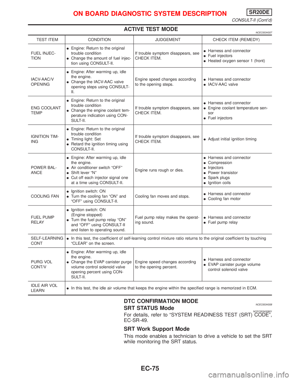
ACTIVE TEST MODENCEC0034S07
TEST ITEM CONDITION JUDGEMENT CHECK ITEM (REMEDY)
FUEL INJEC-
TIONIEngine: Return to the original
trouble condition
IChange the amount of fuel injec-
tion using CONSULT-II.If trouble symptom disappears, see
CHECK ITEM.IHarness and connector
IFuel injectors
IHeated oxygen sensor 1 (front)
IACV-AAC/V
OPENINGIEngine: After warming up, idle
the engine.
IChange the IACV-AAC valve
opening steps using CONSULT-
II.Engine speed changes according
to the opening steps.IHarness and connector
IIACV-AAC valve
ENG COOLANT
TEMPIEngine: Return to the original
trouble condition
IChange the engine coolant tem-
perature indication using CON-
SULT-II.If trouble symptom disappears, see
CHECK ITEM.IHarness and connector
IEngine coolant temperature sen-
sor
IFuel injectors
IGNITION TIM-
INGIEngine: Return to the original
trouble condition
ITiming light: Set
IRetard the ignition timing using
CONSULT-II.If trouble symptom disappears, see
CHECK ITEM.IAdjust initial ignition timing
POWER BAL-
ANCEIEngine: After warming up, idle
the engine.
IAir conditioner switch ªOFFº
IShift lever ªNº
ICut off each injector signal one
at a time using CONSULT-II.Engine runs rough or dies.IHarness and connector
ICompression
IInjectors
IPower transistor
ISpark plugs
IIgnition coils
COOLING FANIIgnition switch: ON
ITurn the cooling fan ªONº and
ªOFFº using CONSULT-II.Cooling fan moves and stops.IHarness and connector
ICooling fan motor
FUEL PUMP
RELAYIIgnition switch: ON
(Engine stopped)
ITurn the fuel pump relay ªONº
and ªOFFº using CONSULT-II
and listen to operating sound.Fuel pump relay makes the operat-
ing sound.IHarness and connector
IFuel pump relay
SELF-LEARNING
CONTIIn this test, the coefficient of self-learning control mixture ratio returns to the original coefficient by touching
ªCLEARº on the screen.
PURG VOL
CONT/VIEngine: After warming up, idle
the engine.
IChange the EVAP canister purge
volume control solenoid valve
opening percent using CON-
SULT-II.Engine speed changes according
to the opening percent.IHarness and connector
IEVAP canister purge volume
control solenoid valve
IDLE AIR VOL
LEARNIIn this test, the idle air volume that keeps the engine within the specified range is memorized in ECM.
DTC CONFIRMATION MODENCEC0034S08SRT STATUS ModeNCEC0034S0801For details, refer to ªSYSTEM READINESS TEST (SRT) CODEº,
EC-SR-49.
SRT Work Support Mode
This mode enables a technician to drive a vehicle to set the SRT
while monitoring the SRT status.
ON BOARD DIAGNOSTIC SYSTEM DESCRIPTIONSR20DE
CONSULT-II (Cont'd)
EC-75
Page 892 of 2267
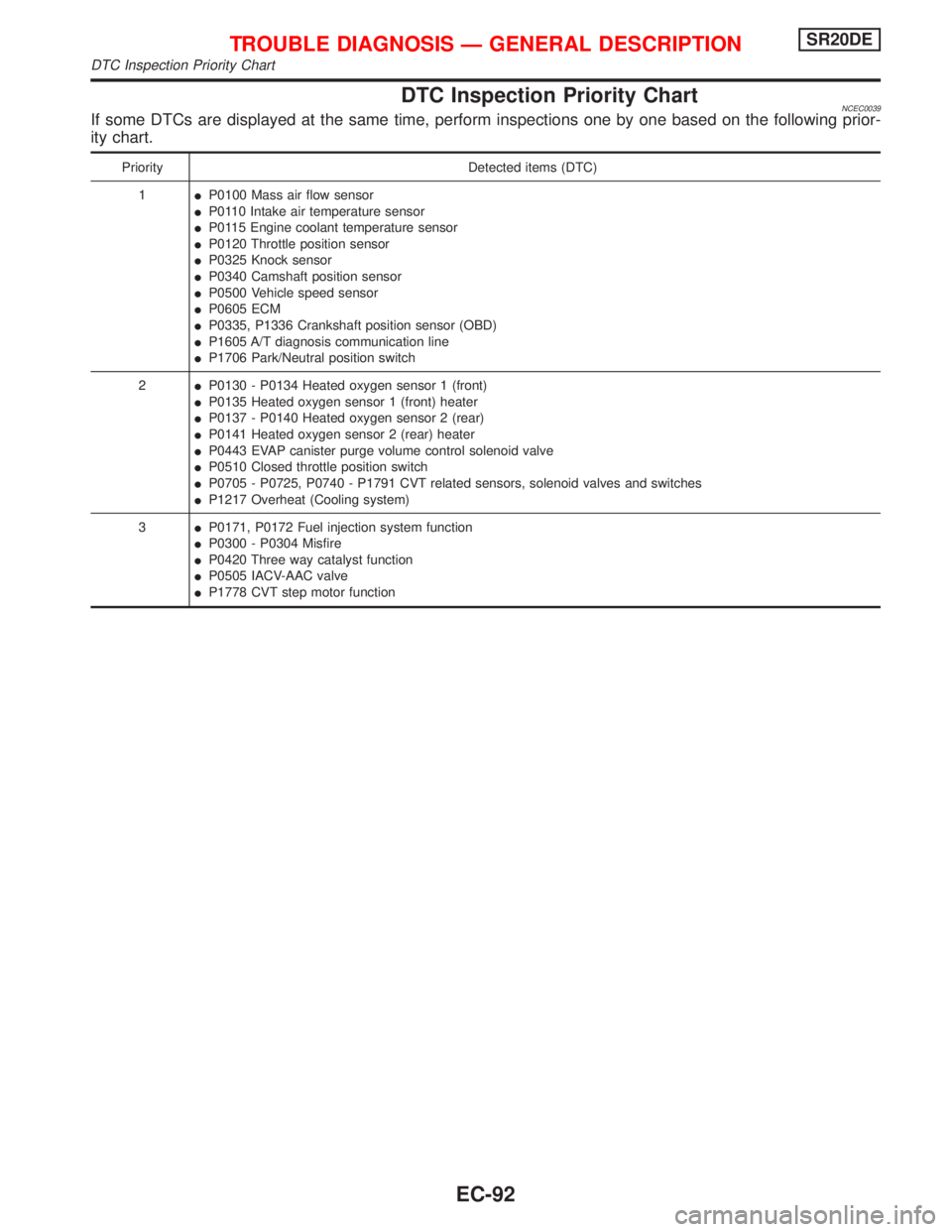
DTC Inspection Priority ChartNCEC0039If some DTCs are displayed at the same time, perform inspections one by one based on the following prior-
ity chart.
Priority Detected items (DTC)
1IP0100 Mass air flow sensor
IP0110 Intake air temperature sensor
IP0115 Engine coolant temperature sensor
IP0120 Throttle position sensor
IP0325 Knock sensor
IP0340 Camshaft position sensor
IP0500 Vehicle speed sensor
IP0605 ECM
IP0335, P1336 Crankshaft position sensor (OBD)
IP1605 A/T diagnosis communication line
IP1706 Park/Neutral position switch
2IP0130 - P0134 Heated oxygen sensor 1 (front)
IP0135 Heated oxygen sensor 1 (front) heater
IP0137 - P0140 Heated oxygen sensor 2 (rear)
IP0141 Heated oxygen sensor 2 (rear) heater
IP0443 EVAP canister purge volume control solenoid valve
IP0510 Closed throttle position switch
IP0705 - P0725, P0740 - P1791 CVT related sensors, solenoid valves and switches
IP1217 Overheat (Cooling system)
3IP0171, P0172 Fuel injection system function
IP0300 - P0304 Misfire
IP0420 Three way catalyst function
IP0505 IACV-AAC valve
IP1778 CVT step motor function
TROUBLE DIAGNOSIS Ð GENERAL DESCRIPTIONSR20DE
DTC Inspection Priority Chart
EC-92
Page 893 of 2267
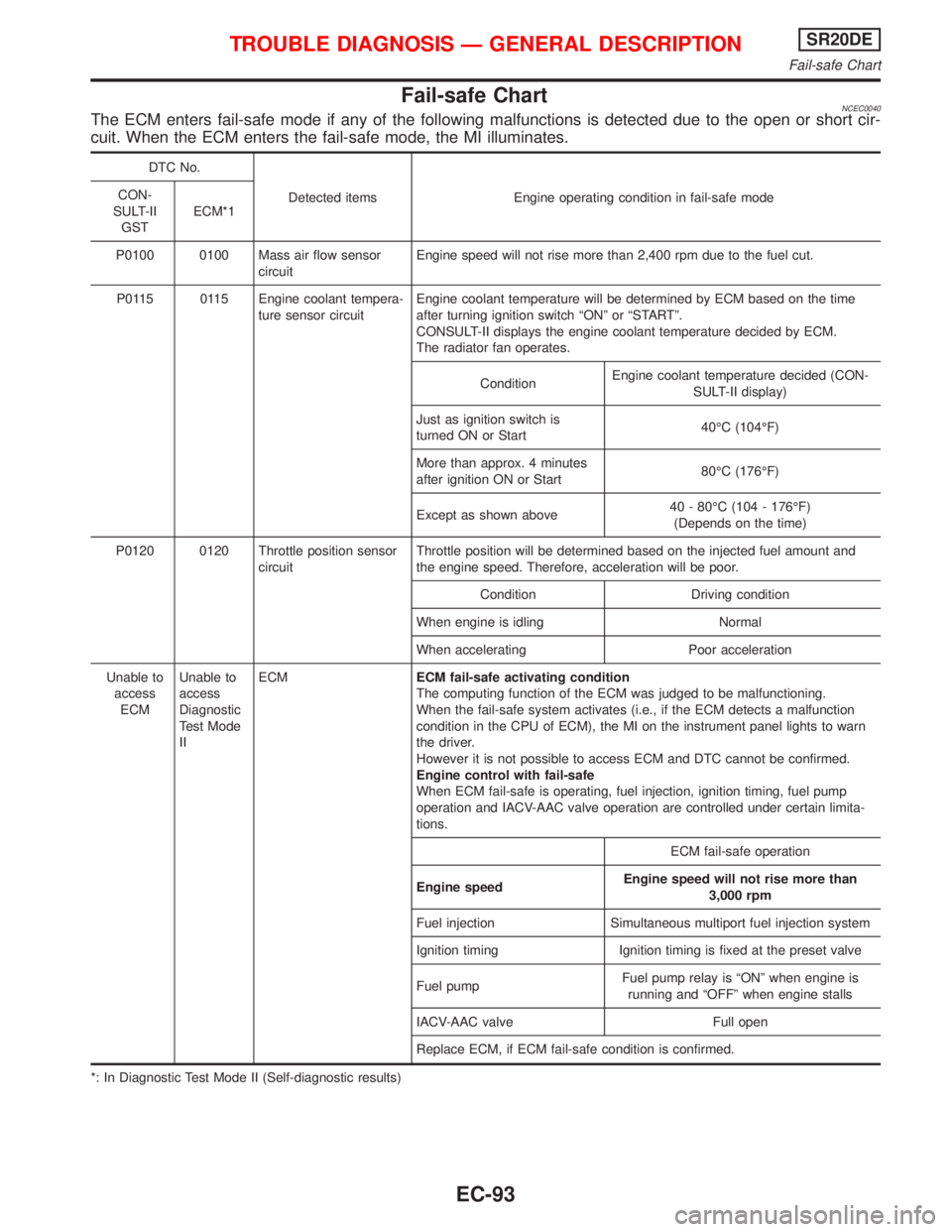
Fail-safe ChartNCEC0040The ECM enters fail-safe mode if any of the following malfunctions is detected due to the open or short cir-
cuit. When the ECM enters the fail-safe mode, the MI illuminates.
DTC No.
Detected items Engine operating condition in fail-safe mode CON-
SULT-II
GSTECM*1
P0100 0100 Mass air flow sensor
circuitEngine speed will not rise more than 2,400 rpm due to the fuel cut.
P0115 0115 Engine coolant tempera-
ture sensor circuitEngine coolant temperature will be determined by ECM based on the time
after turning ignition switch ªONº or ªSTARTº.
CONSULT-II displays the engine coolant temperature decided by ECM.
The radiator fan operates.
ConditionEngine coolant temperature decided (CON-
SULT-II display)
Just as ignition switch is
turned ON or Start40ÉC (104ÉF)
More than approx. 4 minutes
after ignition ON or Start80ÉC (176ÉF)
Except as shown above40 - 80ÉC (104 - 176ÉF)
(Depends on the time)
P0120 0120 Throttle position sensor
circuitThrottle position will be determined based on the injected fuel amount and
the engine speed. Therefore, acceleration will be poor.
Condition Driving condition
When engine is idling Normal
When accelerating Poor acceleration
Unable to
access
ECMUnable to
access
Diagnostic
Test Mode
IIECMECM fail-safe activating condition
The computing function of the ECM was judged to be malfunctioning.
When the fail-safe system activates (i.e., if the ECM detects a malfunction
condition in the CPU of ECM), the MI on the instrument panel lights to warn
the driver.
However it is not possible to access ECM and DTC cannot be confirmed.
Engine control with fail-safe
When ECM fail-safe is operating, fuel injection, ignition timing, fuel pump
operation and IACV-AAC valve operation are controlled under certain limita-
tions.
ECM fail-safe operation
Engine speedEngine speed will not rise more than
3,000 rpm
Fuel injection Simultaneous multiport fuel injection system
Ignition timing Ignition timing is fixed at the preset valve
Fuel pumpFuel pump relay is ªONº when engine is
running and ªOFFº when engine stalls
IACV-AAC valve Full open
Replace ECM, if ECM fail-safe condition is confirmed.
*: In Diagnostic Test Mode II (Self-diagnostic results)
TROUBLE DIAGNOSIS Ð GENERAL DESCRIPTIONSR20DE
Fail-safe Chart
EC-93
Page 895 of 2267
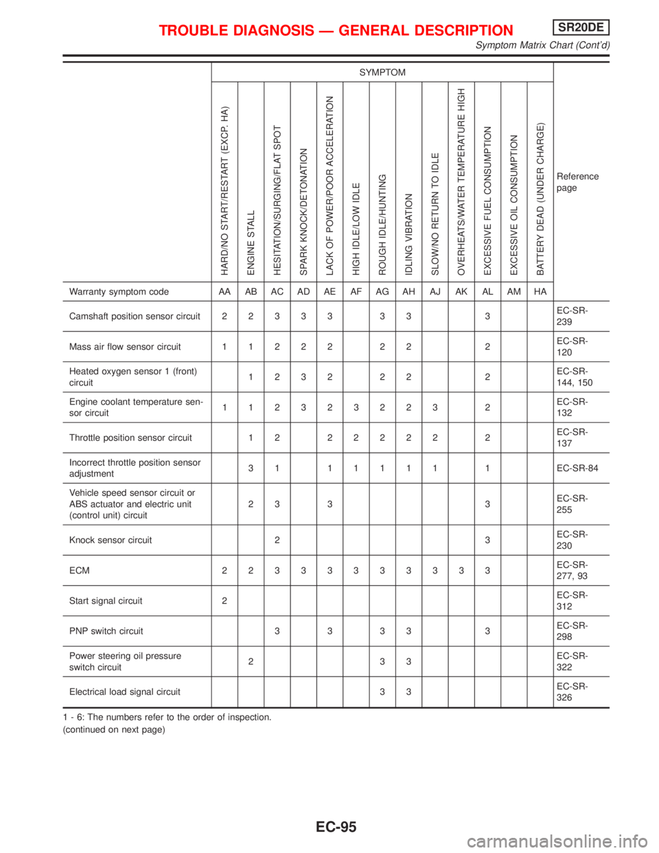
SYMPTOM
Reference
page
HARD/NO START/RESTART (EXCP. HA)
ENGINE STALL
HESITATION/SURGING/FLAT SPOT
SPARK KNOCK/DETONATION
LACK OF POWER/POOR ACCELERATION
HIGH IDLE/LOW IDLE
ROUGH IDLE/HUNTING
IDLING VIBRATION
SLOW/NO RETURN TO IDLE
OVERHEATS/WATER TEMPERATURE HIGH
EXCESSIVE FUEL CONSUMPTION
EXCESSIVE OIL CONSUMPTION
BATTERY DEAD (UNDER CHARGE)
Warranty symptom code AA AB AC AD AE AF AG AH AJ AK AL AM HA
Camshaft position sensor circuit22333 33 3EC-SR-
239
Mass air flow sensor circuit11222 22 2EC-SR-
120
Heated oxygen sensor 1 (front)
circuit1232 22 2EC-SR-
144, 150
Engine coolant temperature sen-
sor circuit112323223 2EC-SR-
132
Throttle position sensor circuit 1 222222 2EC-SR-
137
Incorrect throttle position sensor
adjustment31 11111 1EC-SR-84
Vehicle speed sensor circuit or
ABS actuator and electric unit
(control unit) circuit23 3 3EC-SR-
255
Knock sensor circuit 2 3EC-SR-
230
ECM 22333333333EC-SR-
277, 93
Start signal circuit 2EC-SR-
312
PNP switch circuit 3 3 3 3 3EC-SR-
298
Power steering oil pressure
switch circuit233EC-SR-
322
Electrical load signal circuit 3 3EC-SR-
326
1 - 6: The numbers refer to the order of inspection.
(continued on next page)
TROUBLE DIAGNOSIS Ð GENERAL DESCRIPTIONSR20DE
Symptom Matrix Chart (Cont'd)
EC-95
Page 897 of 2267
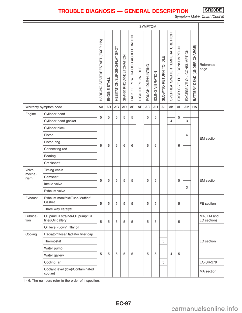
SYMPTOM
Reference
page
HARD/NO START/RESTART (EXCP. HA)
ENGINE STALL
HESITATION/SURGING/FLAT SPOT
SPARK KNOCK/DETONATION
LACK OF POWER/POOR ACCELERATION
HIGH IDLE/LOW IDLE
ROUGH IDLE/HUNTING
IDLING VIBRATION
SLOW/NO RETURN TO IDLE
OVERHEATS/WATER TEMPERATURE HIGH
EXCESSIVE FUEL CONSUMPTION
EXCESSIVE OIL CONSUMPTION
BATTERY DEAD (UNDER CHARGE)
Warranty symptom code AA AB AC AD AE AF AG AH AJ AK AL AM HA
Engine Cylinder head
55555 55 5
EM section Cylinder head gasket 4 3
Cylinder block
66666 66 64 Piston
Piston ring
Connecting rod
Bearing
Crankshaft
Valve
mecha-
nismTiming chain
55555 55 5 EMsection Camshaft
Intake valve
3
Exhaust valve
Exhaust Exhaust manifold/Tube/Muffler/
Gasket
55555 55 5 FEsection
Three way catalyst
Lubrica-
tionOil pan/Oil strainer/Oil pump/Oil
filter/Oil gallery
55555 55 5MA, EM and
LC sections
Oil level (Low)/Filthy oil
LC section Cooling Radiator/Hose/Radiator filler cap
55555 55 45 Thermostat 5
Water pump
Water gallery
Cooling fan 5 EC-SR-279
Coolant level (low)/Contaminated
coolantMA section
1 - 6: The numbers refer to the order of inspection.
TROUBLE DIAGNOSIS Ð GENERAL DESCRIPTIONSR20DE
Symptom Matrix Chart (Cont'd)
EC-97
Page 899 of 2267
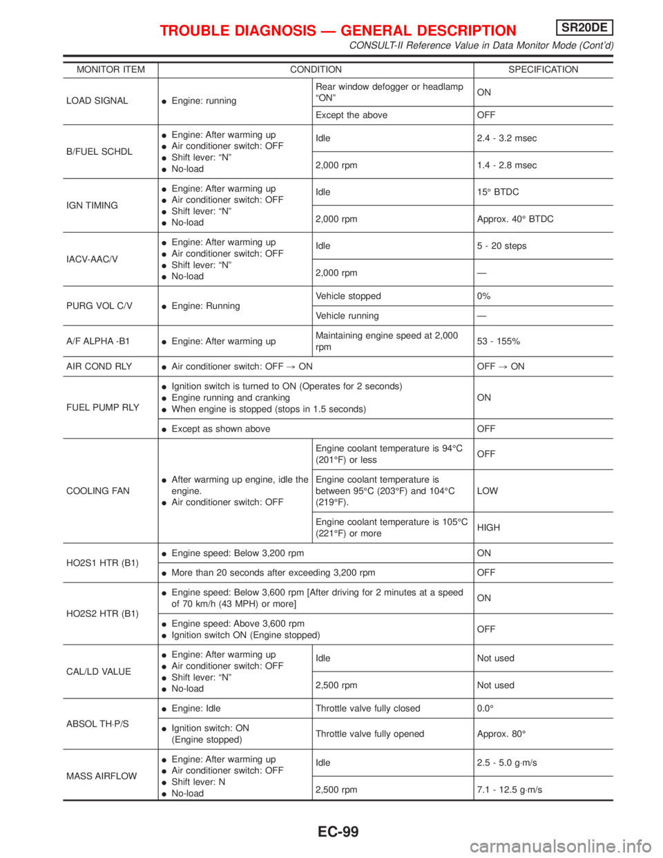
MONITOR ITEM CONDITION SPECIFICATION
LOAD SIGNALIEngine: runningRear window defogger or headlamp
ªONºON
Except the above OFF
B/FUEL SCHDLIEngine: After warming up
IAir conditioner switch: OFF
IShift lever: ªNº
INo-loadIdle 2.4 - 3.2 msec
2,000 rpm 1.4 - 2.8 msec
IGN TIMINGIEngine: After warming up
IAir conditioner switch: OFF
IShift lever: ªNº
INo-loadIdle 15É BTDC
2,000 rpm Approx. 40É BTDC
IACV-AAC/VIEngine: After warming up
IAir conditioner switch: OFF
IShift lever: ªNº
INo-loadIdle 5 - 20 steps
2,000 rpm Ð
PURG VOL C/VIEngine: RunningVehicle stopped 0%
Vehicle running Ð
A/F ALPHA -B1IEngine: After warming upMaintaining engine speed at 2,000
rpm53 - 155%
AIR COND RLYIAir conditioner switch: OFF,ON OFF,ON
FUEL PUMP RLYIIgnition switch is turned to ON (Operates for 2 seconds)
IEngine running and cranking
IWhen engine is stopped (stops in 1.5 seconds)ON
IExcept as shown above OFF
COOLING FANIAfter warming up engine, idle the
engine.
IAir conditioner switch: OFFEngine coolant temperature is 94ÉC
(201ÉF) or lessOFF
Engine coolant temperature is
between 95ÉC (203ÉF) and 104ÉC
(219ÉF).LOW
Engine coolant temperature is 105ÉC
(221ÉF) or moreHIGH
HO2S1 HTR (B1)IEngine speed: Below 3,200 rpm ON
IMore than 20 seconds after exceeding 3,200 rpm OFF
HO2S2 HTR (B1)IEngine speed: Below 3,600 rpm [After driving for 2 minutes at a speed
of 70 km/h (43 MPH) or more]ON
IEngine speed: Above 3,600 rpm
IIgnition switch ON (Engine stopped)OFF
CAL/LD VALUEIEngine: After warming up
IAir conditioner switch: OFF
IShift lever: ªNº
INo-loadIdle Not used
2,500 rpm Not used
ABSOL TH×P/SIEngine: Idle Throttle valve fully closed 0.0É
IIgnition switch: ON
(Engine stopped)Throttle valve fully opened Approx. 80É
MASS AIRFLOWIEngine: After warming up
IAir conditioner switch: OFF
IShift lever: N
INo-loadIdle 2.5 - 5.0 g×m/s
2,500 rpm 7.1 - 12.5 g×m/s
TROUBLE DIAGNOSIS Ð GENERAL DESCRIPTIONSR20DE
CONSULT-II Reference Value in Data Monitor Mode (Cont'd)
EC-99
Page 908 of 2267
![NISSAN PRIMERA 1999 Electronic Repair Manual TERMI-
NAL
NO.WIRE
COLORITEM CONDITION DATA (DC Voltage)
66*2
75L
LCamshaft position sen-
sor (REF)[Engine is running]
IWarm-up condition
IIdle speed0.1 - 0.4V
SEF006W
[Engine is running]
IEngine spee NISSAN PRIMERA 1999 Electronic Repair Manual TERMI-
NAL
NO.WIRE
COLORITEM CONDITION DATA (DC Voltage)
66*2
75L
LCamshaft position sen-
sor (REF)[Engine is running]
IWarm-up condition
IIdle speed0.1 - 0.4V
SEF006W
[Engine is running]
IEngine spee](/manual-img/5/57377/w960_57377-907.png)
TERMI-
NAL
NO.WIRE
COLORITEM CONDITION DATA (DC Voltage)
66*2
75L
LCamshaft position sen-
sor (REF)[Engine is running]
IWarm-up condition
IIdle speed0.1 - 0.4V
SEF006W
[Engine is running]
IEngine speed is 2,000 rpm0.1 - 0.4V
SEF007W
67 W/LPower supply for ECM
(Back-up)[Ignition switch ªOFFº]BATTERY VOLTAGE
(11 - 14V)
70 BR/YEngine coolant tem-
perature sensor[Engine is running]Approximately 0 - 4.8V
Output voltage varies with
engine coolant temperature
71
92Ð
YThrottle position sensor[Engine is running]
IAccelerator pedal released0.35 - 0.65V
[Ignition switch ªONº]
IAccelerator pedal fully depressedApproximately 4V
73 WMass air flow sensor
ground[Engine is running]
IWarm-up condition
IIdle speedApproximately 0V
74 R/LRefrigerant pressure
sensor[Engine is running]
IWarm-up condition
IIdle speed
IAir conditioner is ªONºMore than 1.5V
81 W Knock sensor[Engine is running]
IIdle speed2.0 - 3.0V
85 B/WCamshaft position sen-
sor (Position signal)[Engine is running]
IWarm-up condition
IIdle speedApproximately 2.5V
SEF004W
[Engine is running]
IEngine speed is 2,000 rpmApproximately 2.4V
SEF005W
*2: Models before VIN - P11U0548750
TROUBLE DIAGNOSIS Ð GENERAL DESCRIPTIONSR20DE
ECM Terminals and Reference Value (Cont'd)
EC-108
Page 910 of 2267
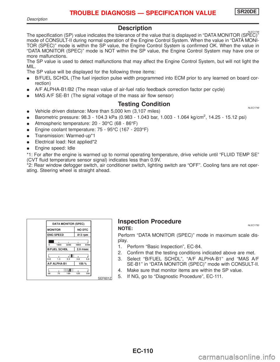
DescriptionNLEC1748The specification (SP) value indicates the tolerance of the value that is displayed in ªDATA MONITOR (SPEC)º
mode of CONSULT-II during normal operation of the Engine Control System. When the value in ªDATA MONI-
TOR (SPEC)º mode is within the SP value, the Engine Control System is confirmed OK. When the value in
ªDATA MONITOR (SPEC)º mode is NOT within the SP value, the Engine Control System may have one or
more malfunctions.
The SP value is used to detect malfunctions that may affect the Engine Control System, but will not light the
MIL.
The SP value will be displayed for the following three items:
IB/FUEL SCHDL (The fuel injection pulse width programmed into ECM prior to any learned on board cor-
rection)
IA/F ALPHA-B1/B2 (The mean value of air-fuel ratio feedback correction factor per cycle)
IMAS A/F SE-B1 (The signal voltage of the mass air flow sensor)
Testing ConditionNLEC1749IVehicle driven distance: More than 5,000 km (3,107 miles)
IBarometric pressure: 98.3 - 104.3 kPa (0.983 - 1.043 bar, 1.003 - 1.064 kg/cm2, 14.25 - 15.12 psi)
IAtmospheric temperature: 20 - 30ÉC (68 - 86ÉF)
IEngine coolant temperature: 75 - 95ÉC (167 - 203ÉF)
ITransmission: Warmed-up*1
IElectrical load: Not applied*2
IEngine speed: Idle
*1: For after the engine is warmed up to normal operating temperature, drive vehicle until ªFLUID TEMP SEº
(CVT fluid temperature sensor signal) indicates less than 0.9V.
*2: Rear window defogger switch, air conditioner switch, lighting switch are ªOFFº. Cooling fans are not oper-
ating. Steering wheel is straight ahead.
SEF601Z
Inspection ProcedureNLEC1750NOTE:
Perform ªDATA MONITOR (SPEC)º mode in maximum scale dis-
play.
1. Perform ªBasic Inspectionº, EC-84.
2. Confirm that the testing conditions indicated above are met.
3. Select ªB/FUEL SCHDLº, ªA/F ALPHA-B1º and ªMAS A/F
SE-B1º in ªDATA MONITOR (SPEC)º mode with CONSULT-II.
4. Make sure that monitor items are within the SP value.
5. If NG, go to ªDiagnostic Procedureº, EC-111.
TROUBLE DIAGNOSIS Ð SPECIFICATION VALUESR20DE
Description
EC-110