Page 1645 of 2267
17. Install rocker cover and oil separator.
IBe sure to install washers between bolts and rocker cover.
ITightening procedure
STEP 1: Tighten bolts1-10-11-13-8inthat order.
STEP 2: Tighten bolts1-13inthat order.
:8-10N×m (0.8 - 1.0 kg-m, 69 - 87 in-lb)
18. Install the following parts:
ISpark plugs and leads
IRadiator
Refit hoses and refill with coolant.
Refer to MA-29, ªChanging Engine Coolantº.
IFront RH wheel
IEngine undercovers
19. Connect the following:
IVacuum hoses
IFuel hoses
IWire harnesses and connectors
IAir duct to intake manifold
IFront exhaust tube
SEM052G Engine
front
Tighten in numerical order.Rocker cover
CYLINDER HEADSR20DE
Installation (Cont'd)
EM-105
Page 1647 of 2267
WARNING:
IPosition vehicle on a flat and solid surface.
IPlace chocks at front and back of rear wheels.
IDo not remove engine until exhaust system has com-
pletely cooled;
Otherwise, you may burn yourself and/or fire may break
out in fuel line.
IBefore disconnecting fuel hose, release fuel pressure
from fuel line.
Refer to ªReleasing Fuel Pressureº in EC section.
IBe sure to hoist engine and transaxle in a safe manner.
IFor engines not equipped with engine slingers, attach
slingers and bolts described in PARTS CATALOG.
CAUTION:
IWhen lifting engine, be sure to clear surrounding parts.
Use special care for accelerator cable, brake lines and
brake master cylinder.
IIn hoisting the engine, always use engine slingers in a
safe manner.
IWhen removing drive shaft, be careful not to damage
grease seal of transaxle.
Removal
1. Remove engine under cover and hood.
2. Drain coolant from both cylinder block, and radiator.
3. Drain engine oil.
4. Remove vacuum hoses, fuel hoses, wires, harness and con-
nectors.
5. Remove exhaust tubes, ball joints and drive shafts.
6. Remove radiator and fans.
7. Remove drive belts.
8. Remove alternator, compressor and power steering oil pump
from engine.
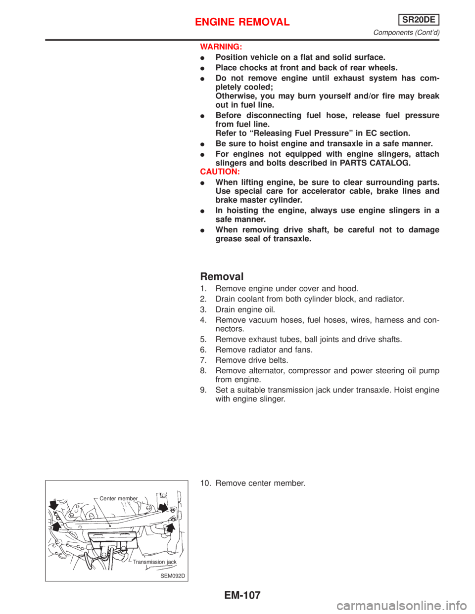
9. Set a suitable transmission jack under transaxle. Hoist engine
with engine slinger.
10. Remove center member.
SEM092D Center member
Transmission jack
ENGINE REMOVALSR20DE
Components (Cont'd)
EM-107
Page 1671 of 2267
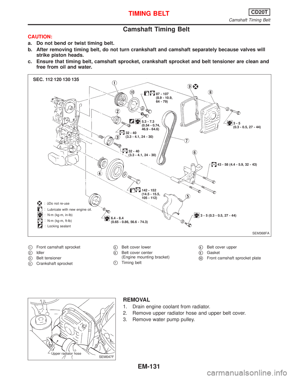
Camshaft Timing Belt
CAUTION:
a. Do not bend or twist timing belt.
b. After removing timing belt, do not turn crankshaft and camshaft separately because valves will
strike piston heads.
c. Ensure that timing belt, camshaft sprocket, crankshaft sprocket and belt tensioner are clean and
free from oil and water.
p1Front camshaft sprocket
p2Idler
p3Belt tensioner
p4Crankshaft sprocket
p5Belt cover lower
p6Belt cover center
(Engine mounting bracket)
p7Timing belt
p8Belt cover upper
p9Gasket
p10Front camshaft sprocket plate
REMOVAL
1. Drain engine coolant from radiator.
2. Remove upper radiator hose and upper belt cover.
3. Remove water pump pulley.
SEM368FA 6.4 - 8.4
(0.65 - 0.86, 56.6 - 74.3) Lubricate with new engine oil.
N´m (kg-m, in-lb)
N´m (kg-m, ft-lb)
Locking sealant5.3 - 7.3
(0.54 - 0.74,
46.9 - 64.6)3-5
(0.3 - 0.5, 27 - 44) 87 - 107
(8.9 - 10.9,
64 - 79)
32-40
(3.3 - 4.1, 24 - 30)
32-40
(3.3 - 4.1, 24 - 30)
142 - 152
(14.5 - 15.5,
105 - 112)
3 - 5 (0.3 - 0.5, 27 - 44)43 - 58 (4.4 - 5.9, 32 - 43)
SEC. 112×120×130×135
: îDo not re-use
SEM047F Upper radiator hose
TIMING BELTCD20T
Camshaft Timing Belt
EM-131
Page 1673 of 2267
Inspection
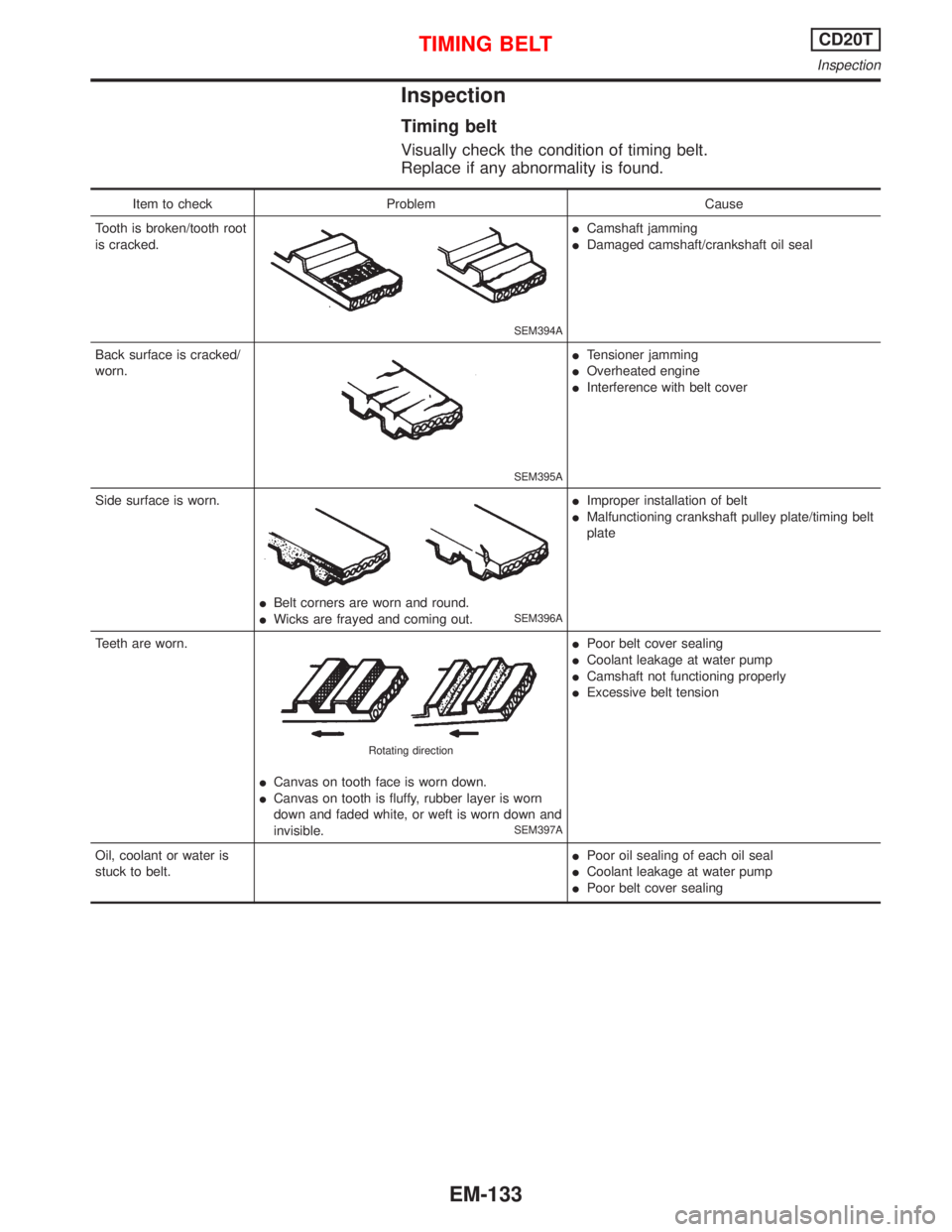
Timing belt
Visually check the condition of timing belt.
Replace if any abnormality is found.
Item to check Problem Cause
Tooth is broken/tooth root
is cracked.
SEM394A
ICamshaft jamming
IDamaged camshaft/crankshaft oil seal
Back surface is cracked/
worn.
SEM395A
ITensioner jamming
IOverheated engine
IInterference with belt cover
Side surface is worn.
IBelt corners are worn and round.
IWicks are frayed and coming out.SEM396A
IImproper installation of belt
IMalfunctioning crankshaft pulley plate/timing belt
plate
Teeth are worn.
ICanvas on tooth face is worn down.
ICanvas on tooth is fluffy, rubber layer is worn
down and faded white, or weft is worn down and
invisible.
SEM397A Rotating direction
IPoor belt cover sealing
ICoolant leakage at water pump
ICamshaft not functioning properly
IExcessive belt tension
Oil, coolant or water is
stuck to belt.IPoor oil sealing of each oil seal
ICoolant leakage at water pump
IPoor belt cover sealing
TIMING BELTCD20T
Inspection
EM-133
Page 1696 of 2267
Removal
1. Disconnect radiator lower hose and drain coolant.
2. Drain coolant from cylinder block.
3. Remove engine under cover.
4. Remove front exhaust tube.
5. Remove air inlet hose from turbocharger unit.
6. Remove connector bolts of turbocharger oil feed tube and
hoses for turbocharger water feed and return tubes.
7. Remove EGR tube.
8. Remove exhaust manifold cover.
9. Remove insulator.
10. Remove turbocharger oil return hose from oil pan.
11. Remove exhaust manifold fixing nuts and bolts.
NEM204
.Turbocharger water
return tube
.Turbocharger water
feed tube
.Turbocharger oil
feed tube
NEM202 Exhaust
manifold
coverAir inlet
hose EGR
tube
Insulator
.NEM203
.Turbocharger
oil return hose
.Oil pan
NEM205 Loosen in numerical order
p1p2
p3p4
TURBOCHARGERCD20T
Removal
EM-156
Page 1703 of 2267
WARNING:
ISituate vehicle on a flat and solid surface.
IPlace chocks at front and back of rear wheels.
IDo not remove engine until exhaust system has com-
pletely cooled down.
IFor safety during subsequent steps, the tension of wires
should be slackened against the engine.
IBefore removing front axle from transaxle, place safety
stands under designated front supporting points. Refer to
GI section for lifting points and towing.
IBe sure to hoist engine and transaxle in a safe manner.
IFor engines not equipped with engine slingers, attach
proper slingers and bolts described in PARTS CATALOG
or Eurofast.
CAUTION:
IWhen lifting engine, be careful not to strike adjacent parts,
especially accelerator wire casing, brake lines, and brake
master cylinder.
IAlways use engine slingers when hoisting the engine.
IWhen removing drive shaft, be careful not to damage tran-
saxle oil seal.
1. Remove engine undercovers and splash covers.
2. Remove front exhaust tube.
3. Disconnect lower water hose from radiator and drain coolant.
4. Drain transaxle oil.
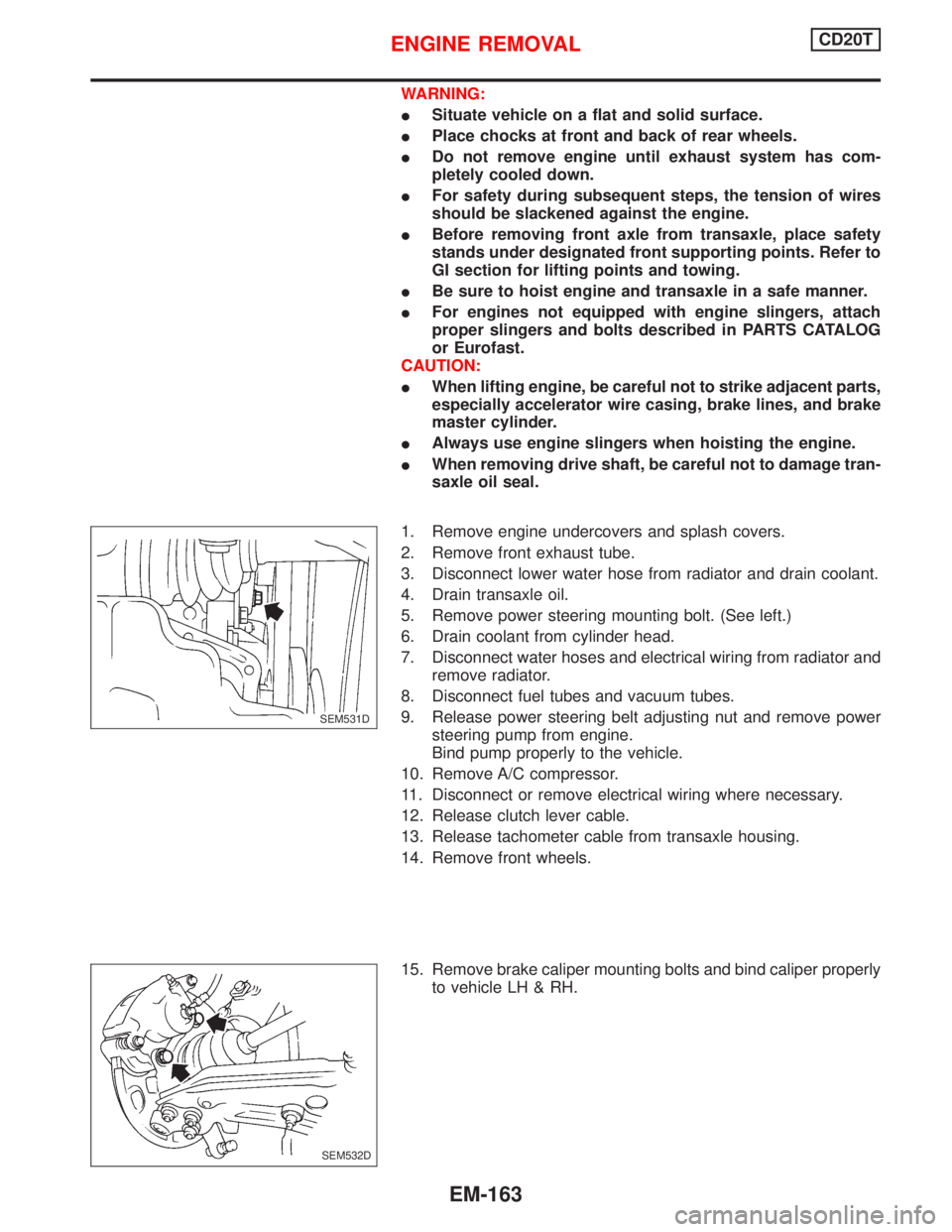
5. Remove power steering mounting bolt. (See left.)
6. Drain coolant from cylinder head.
7. Disconnect water hoses and electrical wiring from radiator and
remove radiator.
8. Disconnect fuel tubes and vacuum tubes.
9. Release power steering belt adjusting nut and remove power
steering pump from engine.
Bind pump properly to the vehicle.
10. Remove A/C compressor.
11. Disconnect or remove electrical wiring where necessary.
12. Release clutch lever cable.
13. Release tachometer cable from transaxle housing.
14. Remove front wheels.
15. Remove brake caliper mounting bolts and bind caliper properly
to vehicle LH & RH.
.SEM531D
SEM532D
ENGINE REMOVALCD20T
EM-163
Page 1707 of 2267
Preparation
IDrill a hole into the attachment (KV10108101).
Disassembly
PISTON AND CRANKSHAFT
1. Place engine on a work stand.
2. Drain coolant and oil.
3. Remove timing belt.
4. Remove water pump.
5. Remove oil pan and oil pump.
6. Remove cylinder head.
7. Remove pistons with connecting rods.
When disassembling piston and connecting rod, heat piston
to 60 to 70ÉC (140 to 158ÉF) or use piston pin press stand at
room temperature.
8. Remove main bearing cap and crankshaft.
Place the bearings and caps in their proper order.
Upper bearings (cylinder block side) have oil groove.
9. Remove piston rings with a tool.
SEM707D
SEM895
SEM360D Piston with connecting rod
Heater
SEM359F Engine front
Loosen in numerical order
SEM291
CYLINDER BLOCKCD20T
Preparation
EM-167
Page 1744 of 2267
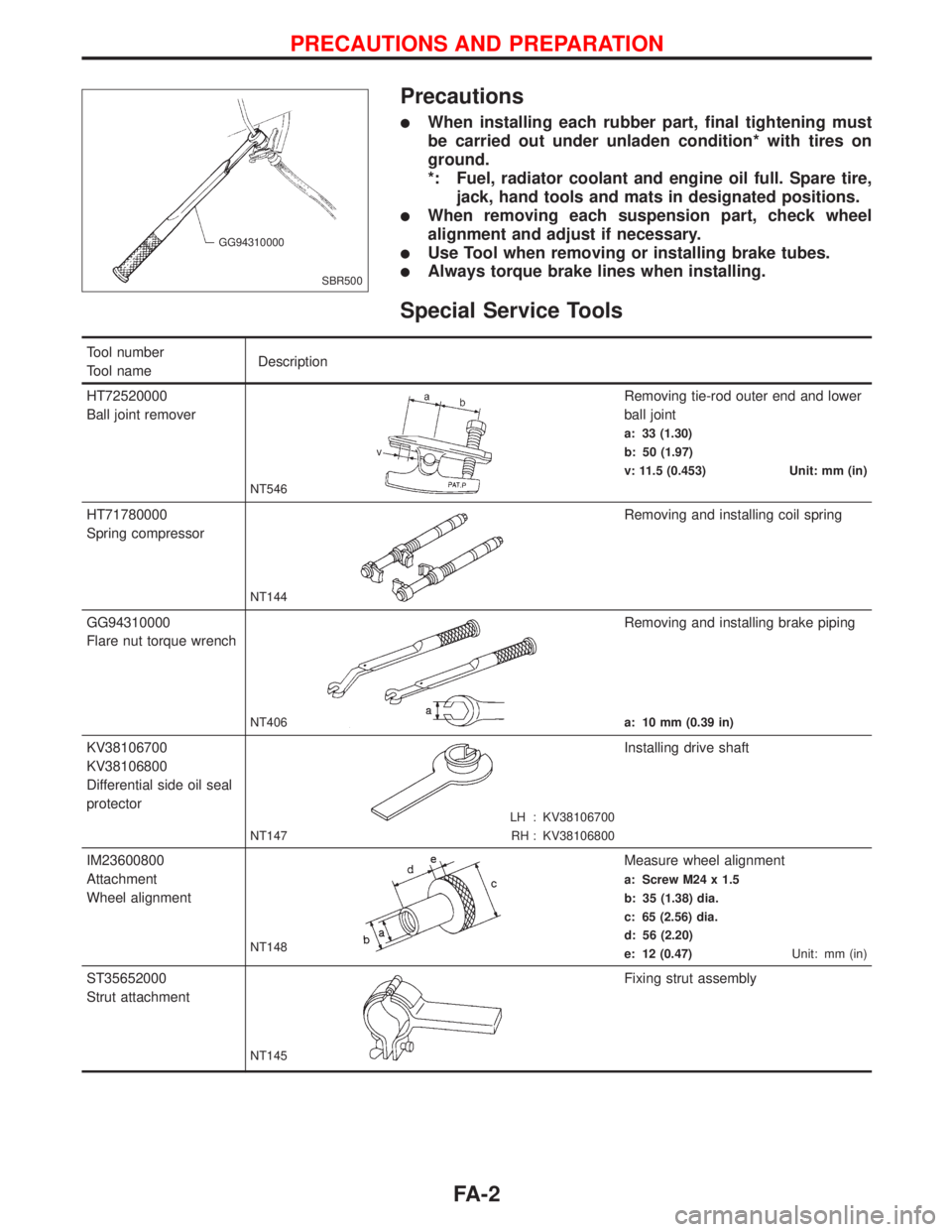
Precautions
lWhen installing each rubber part, final tightening must
be carried out under unladen condition* with tires on
ground.
*: Fuel, radiator coolant and engine oil full. Spare tire,
jack, hand tools and mats in designated positions.
lWhen removing each suspension part, check wheel
alignment and adjust if necessary.
lUse Tool when removing or installing brake tubes.
lAlways torque brake lines when installing.
Special Service Tools
Tool number
Tool nameDescription
HT72520000
Ball joint remover
NT546
Removing tie-rod outer end and lower
ball joint
a: 33 (1.30)
b: 50 (1.97)
v: 11.5 (0.453) Unit: mm (in)
HT71780000
Spring compressor
NT144
Removing and installing coil spring
GG94310000
Flare nut torque wrench
NT406
Removing and installing brake piping
a: 10 mm (0.39 in)
KV38106700
KV38106800
Differential side oil seal
protector
LH : KV38106700
RH : KV38106800 NT147
Installing drive shaft
IM23600800
Attachment
Wheel alignment
NT148
Measure wheel alignment
a: Screw M24 x 1.5
b: 35 (1.38) dia.
c: 65 (2.56) dia.
d: 56 (2.20)
e: 12 (0.47)Unit: mm (in)
ST35652000
Strut attachment
NT145
Fixing strut assembly
SBR500 GG94310000
PRECAUTIONS AND PREPARATION
FA-2