Page 2000 of 2267
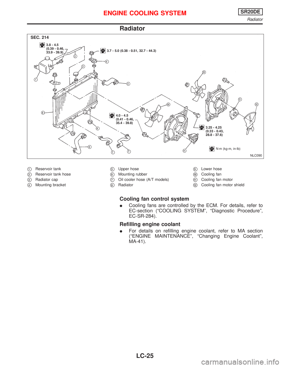
Radiator
�1Reservoir tank
�2Reservoir tank hose
�3Radiator cap
�4Mounting bracket
�5Upper hose
�6Mounting rubber
�7Oil cooler hose (A/T models)
�8Radiator
�9Lower hose
�10Cooling fan
�11Cooling fan motor
�12Cooling fan motor shield
Cooling fan control system
�Cooling fans are controlled by the ECM. For details, refer to
EC-section (“COOLING SYSTEM”,“Diagnostic Procedure”,
EC-SR-284).
Refilling engine coolant
�For details on refilling engine coolant, refer to MA section
(“ENGINE MAINTENANCE”,“Changing Engine Coolant”,
MA-41).
NLC090
3.8 - 4.5
(0.39 - 0.46,
33.9 - 39.9)
3.7 - 5.0 (0.38 - 0.51, 32.7 - 44.3)
4.0 - 4.5
(0.41 - 0.46,
35.4 - 39.8)
3.25 - 4.25
(0.33 - 0.43,
28.8 - 37.6)
�1
�2
�3�4
�5
�6
�7
�8
�9
�10
�11
�11
�10
�7
SEC. 214
�12
N·m (kg-m, in-lb)
ENGINE COOLING SYSTEMSR20DE
Radiator
LC-25
Page 2002 of 2267

Oil Pressure Check
WARNING:
�Be careful not to burn yourself, as the engine and oil may
be hot.
�Oil pressure check should be done in“Neutral”gear posi-
tion.
1. Check oil level.
2. Remove oil pressure switch.
3. Install pressure gauge.
4. Start engine and warm it up to normal operating temperature.
5. Check oil pressure with engine running under no-load.
Engine rpm Approximate discharge pressure
kPa (bar, kg/cm2, psi)
Idle speedMore than 59 (0.59, 0.6, 9)
2,000294 (2.9, 3, 43)
If difference is extreme, check oil passage and oil pump for oil
leaks.
6. Install oil pressure switch with sealant.
Oil Pump
REMOVAL AND INSTALLATION
1. Drain engine coolant and engine oil.
2. Remove upper radiator hose, drive belts, crank pulley, timing
belt covers and timing belt. (Refer to EM section).
3. Remove exhaust front tube, timing belt pulley and rear engine
gusset (bar type), then remove oil pan. (Refer to EM section).
4. Remove crankshaft position sensor (TDC).
5. Remove oil pump assembly with oil strainer.
6. Reinstall any part removed. Refill engine oil and engine cool-
ant.
�Apply liquid gasket to oil pump.
�Apply liquid gasket to oil pan.
�Apply liquid gasket to both ends of oil pan oil seals.
�Install oil pan, fitting oil seals in the correct position.
SLC461
Oil filter
Oil pressure switch
SLC926-A ST2051001
ST25052000
SLC462A Rear engine gusset
SLC087B
9.2 - 10.8 N·m
(0.94 - 1.10 kg-m,
81.4 - 95.6 in-lb)Crankshaft
position
sensor
(TDC)
12 - 16 N·m
(1.2 - 1.6 kg-m,
9 - 12 ft-lb)
ENGINE LUBRICATION SYSTEMCD20T
Oil Pressure Check
LC-27
Page 2005 of 2267
OIL PRESSURE RELIEF VALVE INSPECTION
Inspect oil pressure relief valve (indicated by arrow) for movement,
cracks and breaks by pushing the ball. If replacement is necessary,
remove valve by prying it out with a suitable tool. Install a new valve
by tapping it into place.
Oil Cooler
�1Oil cooler
�2Connector�3O-ring
�4Oil filter bracket�5Gasket
�6Gasket
INSPECTION
1. Check oil cooler element and housing for cracks.
2. Check coolant inlet of oil cooler for clogging by blowing through
it.
Replace it if necessary.
SLC446
SLC084B
34 - 44
(3.5 - 4.5, 25 - 33)
16 - 21
(1.6 - 2.1, 12 - 15)
16 - 21
(1.6 - 2.1, 12 - 15)Front
N·m (kg-m, ft-lb)
Do not re-use
.
�6
SEC. 150⋅213
SLC465A Oil cooler
ENGINE LUBRICATION SYSTEMCD20T
Oil Pump (Cont’d)
LC-30
Page 2008 of 2267

Water Pump
REMOVAL AND INSTALLATION
CAUTION:
�When removing water pump assembly, be careful not to
get coolant on drive belt.
�Water pump cannot be disassembled and should be
replaced as a unit.
�After installing water pump, connect hose and clamp
securely, then check for leaks using radiator cap tester.
1. Remove radiator lower hose from radiator and drain engine
coolant.
2. Drain engine coolant from cylinder block.
3. Remove upper radiator hose, timing belt covers, front engine
mounting bracket and timing belt. (Refer to EM section).
4. Remove timing belt tensioner and idler and timing belt lower
back cover.
5. Remove water pump.
�When installing water pump, replace the gasket with a new
one.
INSPECTION
�Check body assembly for rust or corrosion.
�Check for rough operation due to excessive end play.
.NLC040
.Radiator
.Radiator lower.hose
NLC041 Drain plug
(cylinder block)
.SLC562AA Water pump
SLC086B
22 - 25 N·m (2.2 - 2.6 kg-m, 16 - 19 ft-lb)
SLC760
ENGINE COOLING SYSTEMCD20T
Water Pump
LC-33
Page 2009 of 2267
Thermostat
REMOVAL AND INSTALLATION
1. Drain engine coolant.
2. Remove lower radiator hose.
3. Remove water inlet, then take out thermostat.
4. Before installing thermostat, remove all traces of liquid gasket
from mating surface of each part using a scraper.
5. Apply liquid gasket to water outlet, thermostat housing and
water inlet.
6. Install thermostat with jiggle valve uppermost.
�After installation, run engine for a few minutes, and check
for leaks.
SLC564AA
SEC. 210-211Water outlet
16 - 21 (1.6 - 2.1, 12 - 15)
From oil cooler
From heater unit
16 - 21 (1.6 - 2.1, 12 - 15)
Up
Thermostat
Thermostat housing
Water inlet
16 - 21 (1.6 - 2.1, 12 - 15)
2.5±0.5
(0.098±0.020)
dia.2.5 (0.098)
3.5 (0.138)
Bolt hole
2.5±0.5 (0.098±0.020) dia.
2.5±0.5
(0.098±0.020) dia.Bolt hole
2.5±0.5 (0.098±0.020) dia.
2.5±0.5
(0.098±0.020) dia.
Unit: mm (in)
:N·m (kg-m, ft-lb)
SLC097 Air bleederUpper
Jiggle valve
ENGINE COOLING SYSTEMCD20T
Thermostat
LC-34
Page 2011 of 2267
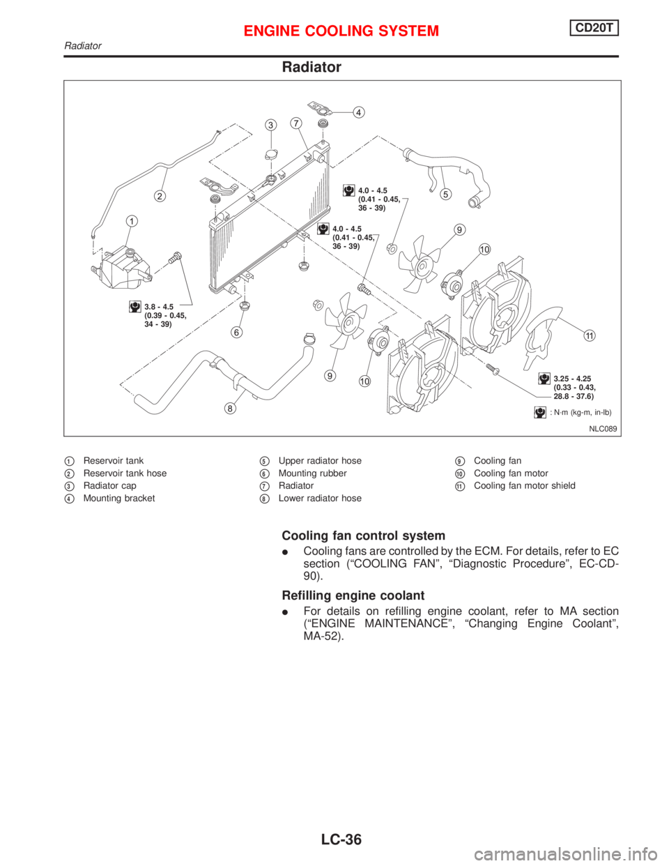
Radiator
�1Reservoir tank
�2Reservoir tank hose
�3Radiator cap
�4Mounting bracket
�5Upper radiator hose
�6Mounting rubber
�7Radiator
�8Lower radiator hose
�9Cooling fan
�10Cooling fan motor
�11Cooling fan motor shield
Cooling fan control system
�Cooling fans are controlled by the ECM. For details, refer to EC
section (“COOLING FAN”,“Diagnostic Procedure”, EC-CD-
90).
Refilling engine coolant
�For details on refilling engine coolant, refer to MA section
(“ENGINE MAINTENANCE”,“Changing Engine Coolant”,
MA-52).
NLC089
3.8 - 4.5
(0.39 - 0.45,
34 - 39)
4.0 - 4.5
(0.41 - 0.45,
36 - 39)
4.0 - 4.5
(0.41 - 0.45,
36 - 39)
3.25 - 4.25
(0.33 - 0.43,
28.8 - 37.6)
:N·m (kg-m, in-lb)
ENGINE COOLING SYSTEMCD20T
Radiator
LC-36
Page 2012 of 2267
Overheating Cause AnalysisNCLC0028
Symptom Check items
Cooling sys-
tem parts
malfunctionPoor heat transferWater pump malfunction Worn or loose drive belt
— Thermostat stuck closed—
Damaged finsDust contamination or
paper clogging
Mechanical damage
Clogged radiator cooling
tubeExcess foreign material
(rust, dirt, sand, etc.)
Reduced air flowCooling fan does not oper-
ate
—— High resistance to fan rota-
tion
Damaged fan blades
Damaged radiator shroud———
Improper coolant mixture
ratio———
Poor coolant quality———
Insufficient coolantCoolant leaksCooling hoseLoose clamp
Cracked hose
Water pump Poor sealing
Radiator capLoose
Poor sealing
RadiatorO-ring for damage, deterio-
ration or improper fitting
Cracked radiator tank
Cracked radiator core
Reservoir tank Cracked reservoir tank
Overflowing reservoir tankExhaust gas leaks into
cooling systemCylinder head deterioration
Cylinder head gasket dete-
rioration
ENGINE COOLING SYSTEM
Overheating Cause Analysis
LC-37
Page 2018 of 2267

MAINTENANCE
SECTION
MA
CONTENTS
PRECAUTIONS AND PREPARATION.......................... 3
Special Service Tools ................................................ 3
Commercial Service Tool ........................................... 3
PRE-DELIVERY INSPECTION ITEMS.......................... 4
GENERAL MAINTENANCE.......................................... 5
PERIODIC MAINTENANCE.......................................... 6
Maintenance Schedule for Petrol Engines
(Annual Mileage < 30,000 km/year) .......................... 6
Chassis and Body Maintenance ................................ 7
Maintenance Schedule for Diesel Engines
(Annual Mileage < 30,000 km/year) .......................... 8
Chassis and Body Maintenance ................................ 9
Maintenance Under Severe Driving Conditions
(Annual Driving Distance < 30,000 km/year) .......... 10
Maintenance Schedule for Petrol Engines
(Annual Mileage > 30,000 km/year) ......................... 11
Chassis and Body Maintenance .............................. 12
Maintenance Schedule for Diesel Engines
(Annual Mileage > 30,000 km/year) ........................ 13
Chassis and Body Maintenance .............................. 14
Maintenance Under Severe Driving Conditions
(Annual Driving Distance > 30,000 km) .................. 15
RECOMMENDED FLUIDS AND LUBRICANTS......... 16
Fluids and Lubricants .............................................. 16
SAE Viscosity Number ............................................ 17
QG
ENGINE MAINTENANCE............................................ 18
Checking Drive Belts ............................................... 18
Changing Engine Coolant........................................ 19
Checking Cooling System ....................................... 21
Checking Radiator Cap ........................................... 21
Checking Fuel Lines ................................................ 22Changing Fuel Filter ................................................ 23
Changing Air Cleaner Filter ..................................... 23
Changing Engine Oil................................................ 24
Changing Engine Oil Filter ...................................... 24
Checking and Changing Spark Plugs ..................... 25
Checking Positive Crankcase Ventilation (PCV)
System ..................................................................... 26
Checking Vacuum Hoses and Connections ............ 26
Checking EVAP Vapour Lines ................................. 26
Checking Front Heated Oxygen Sensor (HO2S) .... 27
SR20DE
ENGINE MAINTENANCE............................................ 28
Checking Drive Belts ............................................... 28
Changing Engine Coolant........................................ 29
Checking Cooling System ....................................... 31
Checking Fuel Lines ................................................ 33
Changing Fuel Filter ................................................ 33
Changing Air Cleaner Filter ..................................... 34
Changing Engine Oil................................................ 34
Changing Engine Oil Filter ...................................... 35
Checking and Changing Spark Plugs ..................... 35
Checking Ignition Leads .......................................... 36
Checking Positive Crankcase Ventilation (PCV)
System ..................................................................... 36
Checking Vacuum Hoses and Connections ............ 37
Checking EVAP Vapor Lines ................................... 37
Checking Front Heated Oxygen Sensor (HO2S) .... 38
CD20T
ENGINE MAINTENANCE............................................ 39
Checking Drive Belts ............................................... 39
Changing Engine Coolant........................................ 40
MA
 for movement,
cracks and breaks by pushing the ball. If replacement is necessary,
remove valve by prying it")