1999 NISSAN PRIMERA engine coolant
[x] Cancel search: engine coolantPage 1746 of 2267
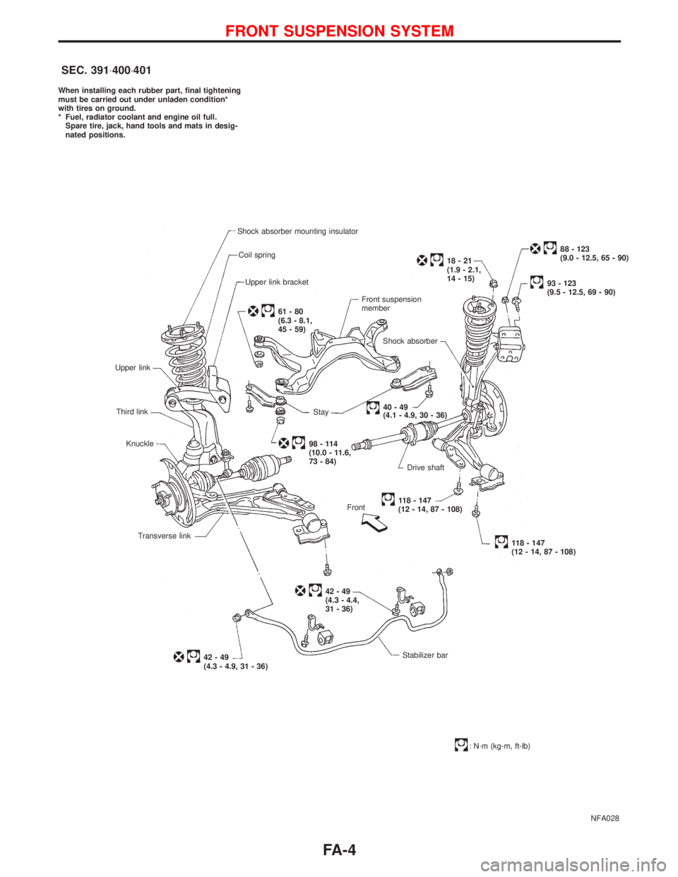
NFA028 When installing each rubber part, final tightening
must be carried out under unladen condition*
with tires on ground.
* Fuel, radiator coolant and engine oil full.
Spare tire, jack, hand tools and mats in desig-
nated positions.
Shock absorber mounting insulator
Coil spring
Upper link bracket
Upper link
Third link
Knuckle
Transverse link
42-49
(4.3 - 4.9, 31 - 36)
61-80
(6.3 - 8.1,
45 - 59)
98-114
(10.0 - 11.6,
73 - 84)
Front
42-49
(4.3 - 4.4,
31 - 36)Front suspension
member
Shock absorber
18-21
(1.9 - 2.1,
14 - 15)
88 - 123
(9.0 - 12.5, 65 - 90)
93 - 123
(9.5 - 12.5, 69 - 90)
Stay
40-49
(4.1 - 4.9, 30 - 36)
Drive shaft
118 - 147
(12 - 14, 87 - 108)
118 - 147
(12 - 14, 87 - 108)
Stabilizer bar
: N´m (kg-m, ft-lb)
SEC. 391×400×401
FRONT SUSPENSION SYSTEM
FA-4
Page 1748 of 2267
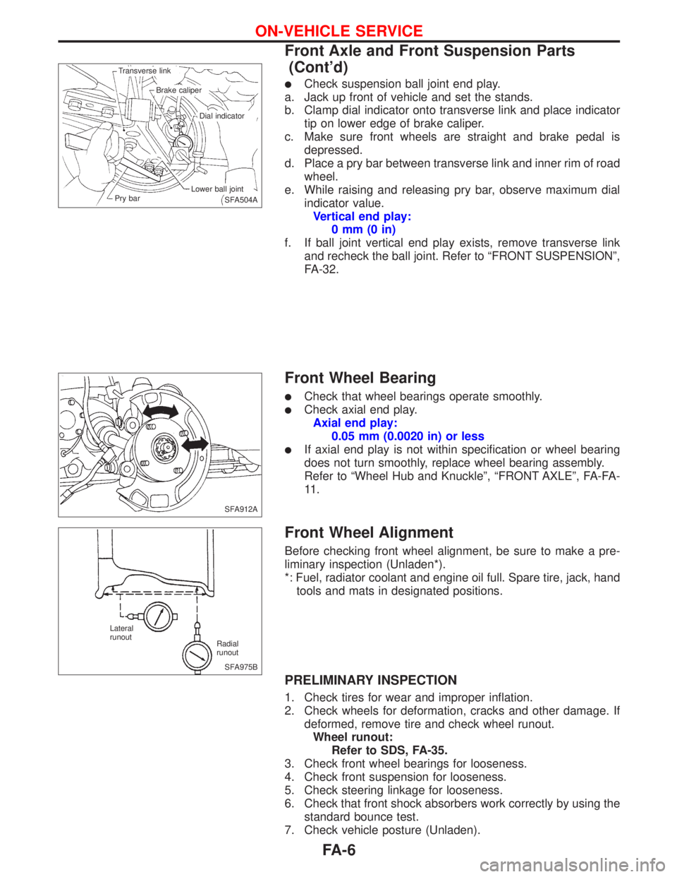
lCheck suspension ball joint end play.
a. Jack up front of vehicle and set the stands.
b. Clamp dial indicator onto transverse link and place indicator
tip on lower edge of brake caliper.
c. Make sure front wheels are straight and brake pedal is
depressed.
d. Place a pry bar between transverse link and inner rim of road
wheel.
e. While raising and releasing pry bar, observe maximum dial
indicator value.
Vertical end play:
0mm(0in)
f. If ball joint vertical end play exists, remove transverse link
and recheck the ball joint. Refer to ªFRONT SUSPENSIONº,
FA-32.
Front Wheel Bearing
lCheck that wheel bearings operate smoothly.
lCheck axial end play.
Axial end play:
0.05 mm (0.0020 in) or less
lIf axial end play is not within specification or wheel bearing
does not turn smoothly, replace wheel bearing assembly.
Refer to ªWheel Hub and Knuckleº, ªFRONT AXLEº, FA-FA-
11 .
Front Wheel Alignment
Before checking front wheel alignment, be sure to make a pre-
liminary inspection (Unladen*).
*: Fuel, radiator coolant and engine oil full. Spare tire, jack, hand
tools and mats in designated positions.
PRELIMINARY INSPECTION
1. Check tires for wear and improper inflation.
2. Check wheels for deformation, cracks and other damage. If
deformed, remove tire and check wheel runout.
Wheel runout:
Refer to SDS, FA-35.
3. Check front wheel bearings for looseness.
4. Check front suspension for looseness.
5. Check steering linkage for looseness.
6. Check that front shock absorbers work correctly by using the
standard bounce test.
7. Check vehicle posture (Unladen).
SFA504A Transverse link
Brake caliper
Dial indicator
Lower ball joint
Pry bar
SFA912A
SFA975B Lateral
runout
Radial
runout
ON-VEHICLE SERVICE
Front Axle and Front Suspension Parts
(Cont'd)
FA-6
Page 1768 of 2267
MODELS BEFORE VIN - P11U0559000
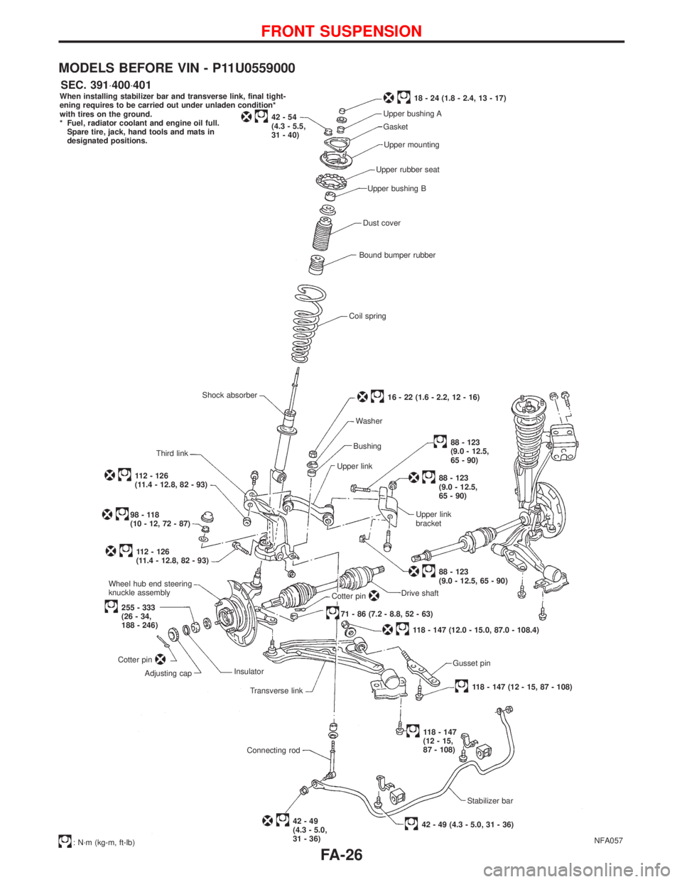
NFA057 When installing stabilizer bar and transverse link, final tight-
ening requires to be carried out under unladen condition*
with tires on the ground.
* Fuel, radiator coolant and engine oil full.
Spare tire, jack, hand tools and mats in
designated positions.
42-54
(4.3 - 5.5,
31 - 40)
18 - 24 (1.8 - 2.4, 13 - 17)
Upper bushing A
Gasket
Upper mounting
Upper rubber seat
Upper bushing B
Dust cover
Bound bumper rubber
Coil spring
16 - 22 (1.6 - 2.2, 12 - 16)
Washer
Bushing
Upper link
88 - 123
(9.0 - 12.5,
65 - 90)
88 - 123
(9.0 - 12.5,
65 - 90)
Upper link
bracket
88 - 123
(9.0 - 12.5, 65 - 90)
Drive shaft
Cotter pin.71 - 86 (7.2 - 8.8, 52 - 63)
118 - 147 (12.0 - 15.0, 87.0 - 108.4)
Gusset pin
118 - 147 (12 - 15, 87 - 108)
118 - 147
(12 - 15,
87 - 108)
Stabilizer bar
42 - 49 (4.3 - 5.0, 31 - 36)42-49
(4.3 - 5.0,
31 - 36) Connecting rodTransverse link Insulator
Adjusting cap Cotter pin
255 - 333
(26 - 34,
188 - 246) Wheel hub end steering
knuckle assembly
112 - 126
(11.4 - 12.8, 82 - 93)
98-118
(10 - 12, 72 - 87)
112 - 126
(11.4 - 12.8, 82 - 93)Third linkShock absorber
: N´m (kg-m, ft-lb)
SEC. 391×400×401
FRONT SUSPENSION
FA-26
Page 1777 of 2267
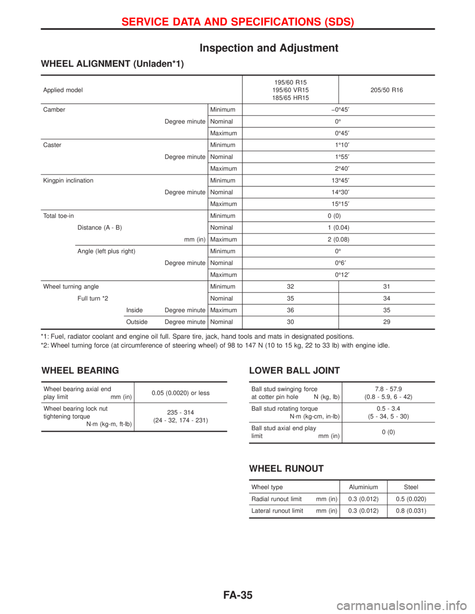
Inspection and Adjustment
WHEEL ALIGNMENT (Unladen*1)
Applied model195/60 R15
195/60 VR15
185/65 HR15205/50 R16
Camber Minimum þ0É45¢
Degree minute Nominal 0É
Maximum 0É45¢
Caster Minimum 1É10¢
Degree minute Nominal 1É55¢
Maximum 2É40¢
Kingpin inclination Minimum 13É45¢
Degree minute Nominal 14É30¢
Maximum 15É15¢
Total toe-in Minimum 0 (0)
Distance (A - B) Nominal 1 (0.04)
mm (in) Maximum 2 (0.08)
Angle (left plus right) Minimum 0É
Degree minute Nominal 0É6¢
Maximum 0É12¢
Wheel turning angle Minimum 32 31
Full turn *2 Nominal 35 34
Inside Degree minute Maximum 36 35
Outside Degree minute Nominal 30 29
*1: Fuel, radiator coolant and engine oil full. Spare tire, jack, hand tools and mats in designated positions.
*2: Wheel turning force (at circumference of steering wheel) of 98 to 147 N (10 to 15 kg, 22 to 33 lb) with engine idle.
WHEEL BEARING
Wheel bearing axial end
play limit mm (in)0.05 (0.0020) or less
Wheel bearing lock nut
tightening torque
N´m (kg-m, ft-lb)235 - 314
(24 - 32, 174 - 231)
LOWER BALL JOINT
Ball stud swinging force
at cotter pin hole N (kg, lb)7.8 - 57.9
(0.8 - 5.9, 6 - 42)
Ball stud rotating torque
N´m (kg-cm, in-lb)0.5 - 3.4
(5 - 34, 5 - 30)
Ball stud axial end play
limit mm (in)0 (0)
WHEEL RUNOUT
Wheel type Aluminium Steel
Radial runout limit mm (in) 0.3 (0.012) 0.5 (0.020)
Lateral runout limit mm (in) 0.3 (0.012) 0.8 (0.031)
SERVICE DATA AND SPECIFICATIONS (SDS)
FA-35
Page 1815 of 2267
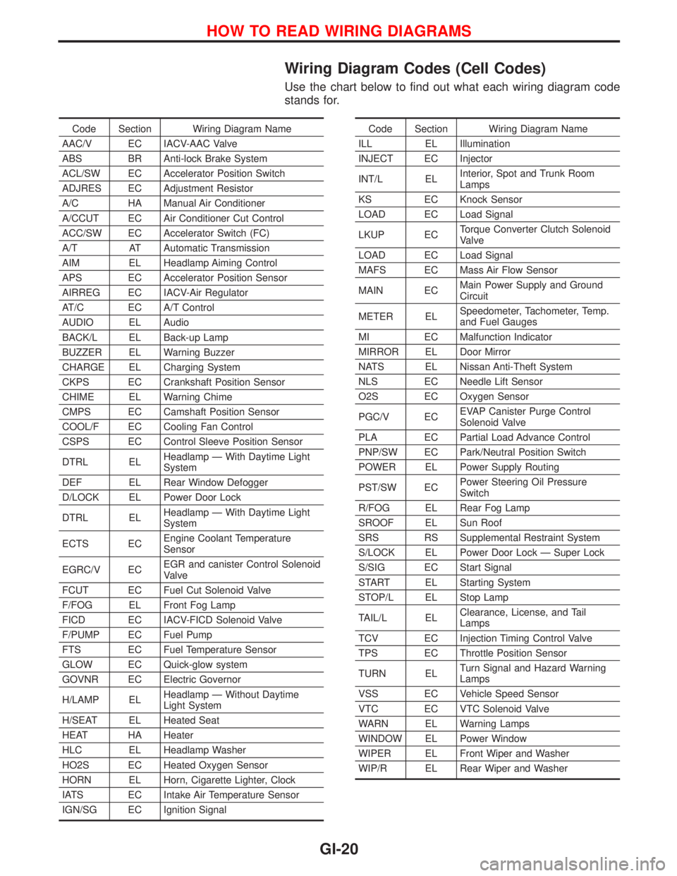
Wiring Diagram Codes (Cell Codes)
Use the chart below to find out what each wiring diagram code
stands for.
Code Section Wiring Diagram Name
AAC/V EC IACV-AAC Valve
ABS BR Anti-lock Brake System
ACL/SW EC Accelerator Position Switch
ADJRES EC Adjustment Resistor
A/C HA Manual Air Conditioner
A/CCUT EC Air Conditioner Cut Control
ACC/SW EC Accelerator Switch (FC)
A/T AT Automatic Transmission
AIM EL Headlamp Aiming Control
APS EC Accelerator Position Sensor
AIRREG EC IACV-Air Regulator
AT/C EC A/T Control
AUDIO EL Audio
BACK/L EL Back-up Lamp
BUZZER EL Warning Buzzer
CHARGE EL Charging System
CKPS EC Crankshaft Position Sensor
CHIME EL Warning Chime
CMPS EC Camshaft Position Sensor
COOL/F EC Cooling Fan Control
CSPS EC Control Sleeve Position Sensor
DTRL ELHeadlamp Ð With Daytime Light
System
DEF EL Rear Window Defogger
D/LOCK EL Power Door Lock
DTRL ELHeadlamp Ð With Daytime Light
System
ECTS ECEngine Coolant Temperature
Sensor
EGRC/V ECEGR and canister Control Solenoid
Valve
FCUT EC Fuel Cut Solenoid Valve
F/FOG EL Front Fog Lamp
FICD EC IACV-FICD Solenoid Valve
F/PUMP EC Fuel Pump
FTS EC Fuel Temperature Sensor
GLOW EC Quick-glow system
GOVNR EC Electric Governor
H/LAMP ELHeadlamp Ð Without Daytime
Light System
H/SEAT EL Heated Seat
HEAT HA Heater
HLC EL Headlamp Washer
HO2S EC Heated Oxygen Sensor
HORN EL Horn, Cigarette Lighter, Clock
IATS EC Intake Air Temperature Sensor
IGN/SG EC Ignition SignalCode Section Wiring Diagram Name
ILL EL Illumination
INJECT EC Injector
INT/L ELInterior, Spot and Trunk Room
Lamps
KS EC Knock Sensor
LOAD EC Load Signal
LKUP ECTorque Converter Clutch Solenoid
Valve
LOAD EC Load Signal
MAFS EC Mass Air Flow Sensor
MAIN ECMain Power Supply and Ground
Circuit
METER ELSpeedometer, Tachometer, Temp.
and Fuel Gauges
MI EC Malfunction Indicator
MIRROR EL Door Mirror
NATS EL Nissan Anti-Theft System
NLS EC Needle Lift Sensor
O2S EC Oxygen Sensor
PGC/V ECEVAP Canister Purge Control
Solenoid Valve
PLA EC Partial Load Advance Control
PNP/SW EC Park/Neutral Position Switch
POWER EL Power Supply Routing
PST/SW ECPower Steering Oil Pressure
Switch
R/FOG EL Rear Fog Lamp
SROOF EL Sun Roof
SRS RS Supplemental Restraint System
S/LOCK EL Power Door Lock Ð Super Lock
S/SIG EC Start Signal
START EL Starting System
STOP/L EL Stop Lamp
TAIL/L ELClearance, License, and Tail
Lamps
TCV EC Injection Timing Control Valve
TPS EC Throttle Position Sensor
TURN ELTurn Signal and Hazard Warning
Lamps
VSS EC Vehicle Speed Sensor
VTC EC VTC Solenoid Valve
WARN EL Warning Lamps
WINDOW EL Power Window
WIPER EL Front Wiper and Washer
WIP/R EL Rear Wiper and Washer
HOW TO READ WIRING DIAGRAMS
GI-20
Page 1846 of 2267
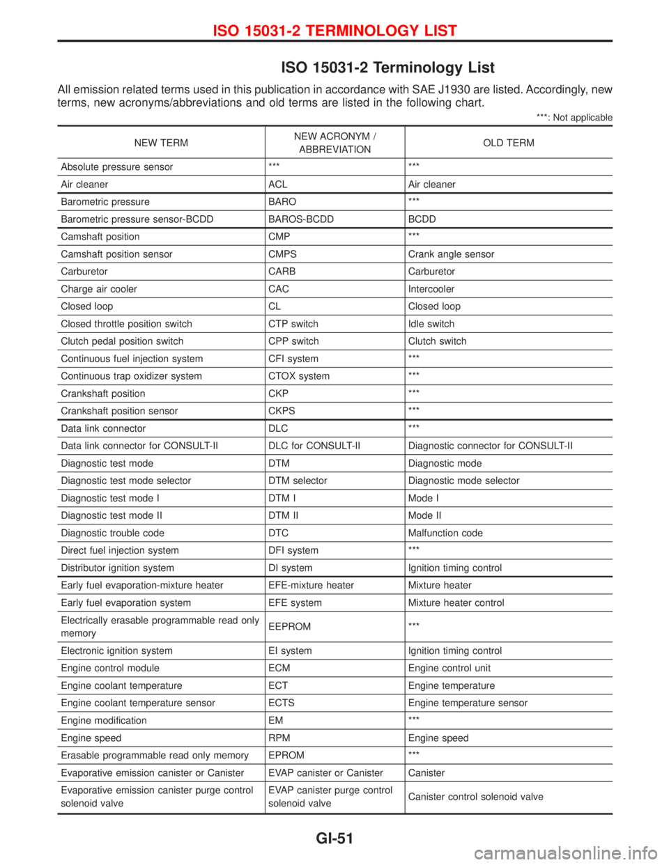
ISO 15031-2 Terminology List
All emission related terms used in this publication in accordance with SAE J1930 are listed. Accordingly, new
terms, new acronyms/abbreviations and old terms are listed in the following chart.
***: Not applicable
NEW TERMNEW ACRONYM /
ABBREVIATIONOLD TERM
Absolute pressure sensor *** ***
Air cleaner ACL Air cleaner
Barometric pressure BARO ***
Barometric pressure sensor-BCDD BAROS-BCDD BCDD
Camshaft position CMP ***
Camshaft position sensor CMPS Crank angle sensor
Carburetor CARB Carburetor
Charge air cooler CAC Intercooler
Closed loop CL Closed loop
Closed throttle position switch CTP switch Idle switch
Clutch pedal position switch CPP switch Clutch switch
Continuous fuel injection system CFI system ***
Continuous trap oxidizer system CTOX system ***
Crankshaft position CKP ***
Crankshaft position sensor CKPS ***
Data link connector DLC ***
Data link connector for CONSULT-II DLC for CONSULT-II Diagnostic connector for CONSULT-II
Diagnostic test mode DTM Diagnostic mode
Diagnostic test mode selector DTM selector Diagnostic mode selector
Diagnostic test mode I DTM I Mode I
Diagnostic test mode II DTM II Mode II
Diagnostic trouble code DTC Malfunction code
Direct fuel injection system DFI system ***
Distributor ignition system DI system Ignition timing control
Early fuel evaporation-mixture heater EFE-mixture heater Mixture heater
Early fuel evaporation system EFE system Mixture heater control
Electrically erasable programmable read only
memoryEEPROM ***
Electronic ignition system EI system Ignition timing control
Engine control module ECM Engine control unit
Engine coolant temperature ECT Engine temperature
Engine coolant temperature sensor ECTS Engine temperature sensor
Engine modification EM ***
Engine speed RPM Engine speed
Erasable programmable read only memory EPROM ***
Evaporative emission canister or Canister EVAP canister or Canister Canister
Evaporative emission canister purge control
solenoid valveEVAP canister purge control
solenoid valveCanister control solenoid valve
ISO 15031-2 TERMINOLOGY LIST
GI-51
Page 1869 of 2267
Introduction
The automatic temperature control (ATC) system provides automatic regulation of the discharged air tem-
perature and the discharged air volume (Blower speed).
The air outlet door, intake door and compressor magnet clutch are controlled by the manual operation of
each switch.
Features
Air mix door control (Automatic temperature control)
The air mix door is automatically controlled so that in-vehicle temperature will reach, and be maintained at
the operator selected ªset temperatureº. For a given set temperature, the air mix door position will depend
on: Ambient temperature, in-vehicle temperature, amount of sunload, set temperature and A/C switch sig-
nals.
Fan speed control
When the fan control switch is in the Auto position, the blower speed is automatically controlled, depending
on: Ambient temperature, in-vehicle temperature, amount of sunload, set temperature, and A/C switch sig-
nals. It is also controlled by the manual operation of the fan control switch.
Starting fan speed control
When engine coolant temperature is low, the air outlet door position is detected by the A/C control panel
and if this is set in B/L, FOOT or FOOT/DEF blower speed is controlled to prevent a large amount of cold
air from being discharged into the floor area.
Outlet door control
This can be selected by operation of the mode control knob.
Intake door control
This can be selected by changing the REC switch position.
Compressor magnet clutch control
System with CR-14 compressor
When the A/C switch is ON, the thermistor detects evaporator temperature. The thermo control amplifier
controls clutch ON/OFF operation depending on the evaporator temperature.
System with CSV613 compressor
Under normal operating conditions, when the A/C is switched on, the compressor runs continuously, and the
evaporator pressure, and therefore temperature, is controlled by the CSV613 variable displacement com-
pressor to prevent freeze up.
DESCRIPTIONAUTO
HA-20
Page 1947 of 2267
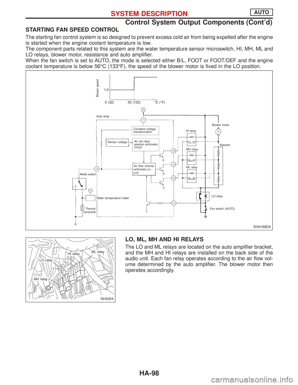
STARTING FAN SPEED CONTROL
The starting fan control system is so designed to prevent excess cold air from being expelled after the engine
is started when the engine coolant temperature is low.
The component parts related to this system are the water temperature sensor microswitch, HI, MH, ML and
LO relays, blower motor, resistance and auto amplifier.
When the fan switch is set to AUTO, the mode is selected either B/L, FOOT or FOOT/DEF and the engine
coolant temperature is below 56ÉC (133ÉF), the speed of the blower motor is fixed in the LO position.
LO, ML, MH AND HI RELAYS
The LO and ML relays are located on the auto amplifier bracket,
and the MH and HI relays are installed on the back side of the
audio unit. Each fan relay operates according to the air flow vol-
ume determined by the auto amplifier. The blower motor then
operates accordingly.
SHA188DA
Blower speed
1.0
0 (32) 50 (122) ÉC (ÉF)
Auto amp.
.Constant voltage
transformation
Sensor voltage
.Air mix door
position arithmetic
circuit
Air flow volume
arithmetic cir-
cuit
Mode switch
Water temperature meter
Thermal
transmitterFan switch (AUTO)LO relay ML relay MH relay HI relay
.Blower motor
Resistor
NHA304
.LO relay
.ML relay.HI relay
.MH relay
SYSTEM DESCRIPTIONAUTO
Control System Output Components (Cont'd)
HA-98