Page 2058 of 2267
Air relief plug:
:8-9N·m (0.8 - 0.9 kg-m, 5.9 - 6.6 ft-lb)
�Use genuine NISSAN Anti-Freeze Coolant or equivalent.
Refer to“RECOMMENDED FLUIDS AND LUBRICANTS”,
MA-16.
Coolant capacity (With reservoir tank):
Unit:�(Imp qt)
CD20T6.1 (5-3/8)
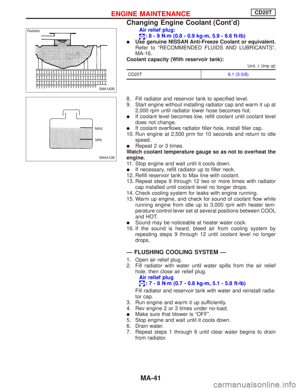
8. Fill radiator and reservoir tank to specified level.
9. Start engine without installing radiator cap and warm it up at
2,000 rpm until radiator lower hose becomes hot.
�If coolant level becomes low, refill coolant until coolant level
does not change.
�If coolant overflows radiator filler hole, install filler cap.
10. Run engine at 2,500 prm for 10 seconds and return to idle
speed.
�Repeat 2 or 3 times.
Watch coolant temperature gauge so as not to overheat the
engine.
11. Stop engine and wait until it cools down.
�If necessary, refill radiator up to filler neck.
12. Refill reservoir tank to Max line with coolant.
13. Repeat steps 9 through 12 two or more times with radiator
cap installed until coolant level no longer drops.
14. Check cooling system for leaks with engine running.
15. Warm up engine, and check for sound of coolant flow while
running engine from idle up to 3,000 rpm with heater tem-
perature control lever set at several positions between COOL
and HOT.
�Sound may be noticeable at heater water cock.
16. If the sound is heard, bleed air from cooling system by
repeating steps 9 through 12 until coolant level no longer
drops.
—FLUSHING COOLING SYSTEM—
1. Open air relief plug.
2. Fill radiator with water until water spills from the air relief
hole, then close air relief plug.
Air relief plug
:7-8N·m (0.7 - 0.8 kg-m, 5.1 - 5.8 ft-lb)
Fill radiator and reservoir tank with water and reinstall radia-
tor cap.
3. Run engine and warm it up sufficiently.
4. Rev engine 2 or 3 times under no-load.
�Make sure that blower is“OFF”.
5. Stop engine and wait until it cools down.
6. Drain water.
7. Repeat steps 1 through 6 until clear water begins to drain
from radiator.
SMA182B Radiator
SMA412B MAX.
MIN.
ENGINE MAINTENANCECD20T
Changing Engine Coolant (Cont’d)
MA-41
Page 2059 of 2267
Checking Cooling System
CHECKING HOSES
Check hoses for proper attachment and for leaks, cracks,
damage, loose connections, chafing and deterioration.
CHECKING RADIATOR
Check radiator for mud or clogging. If necessary, clean radiator
as follows.
�Be careful not to bend or damage the radiator fins.
�When radiator is cleaned without removal, remove all sur-
rounding parts such as cooling fan, radiator shroud and
horns. Then tape the harness and connectors to prevent
water from entering.
1. Apply water by hose to the back side of the radiator core
vertically downward.
2. Apply water again to all radiator core surfaces once per
minute.
3. Stop washing if any stains no longer flow out from the radia-
tor.
4. Blow air into the back side of radiator core vertically down-
ward.
�Use compressed air lower than 5 kg/cm2and keep distance
more than 30 cm (11.8 in).
5. Blow air again into all the radiator core surfaces once per
minute until no water sprays out.
CHECKING RADIATOR CAP
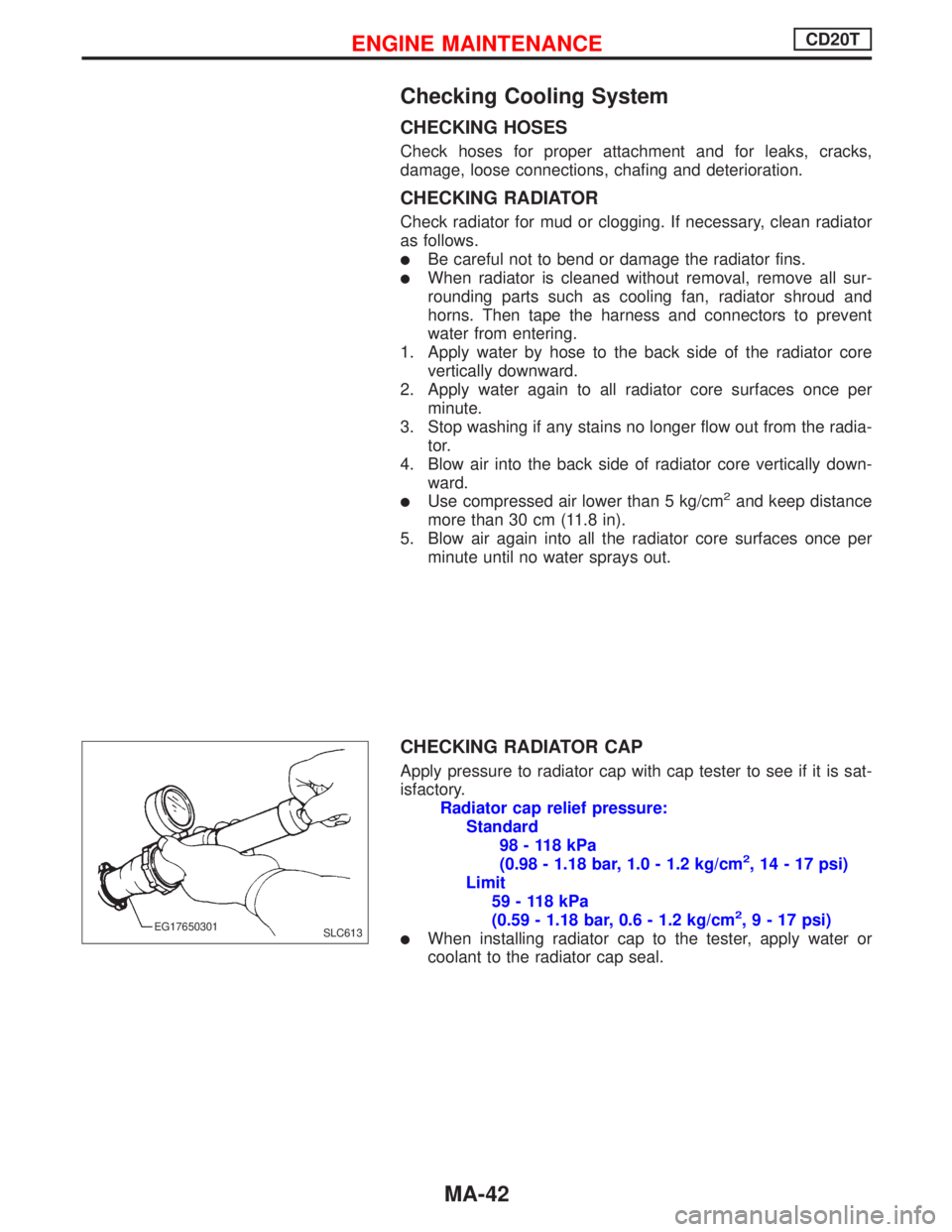
Apply pressure to radiator cap with cap tester to see if it is sat-
isfactory.
Radiator cap relief pressure:
Standard
98 - 118 kPa
(0.98 - 1.18 bar, 1.0 - 1.2 kg/cm
2, 14 - 17 psi)
Limit
59 - 118 kPa
(0.59 - 1.18 bar, 0.6 - 1.2 kg/cm
2,9-17psi)
�When installing radiator cap to the tester, apply water or
coolant to the radiator cap seal.SLC613 EG17650301
ENGINE MAINTENANCECD20T
MA-42
Page 2073 of 2267
Engine Maintenance
INSPECTION AND ADJUSTMENT
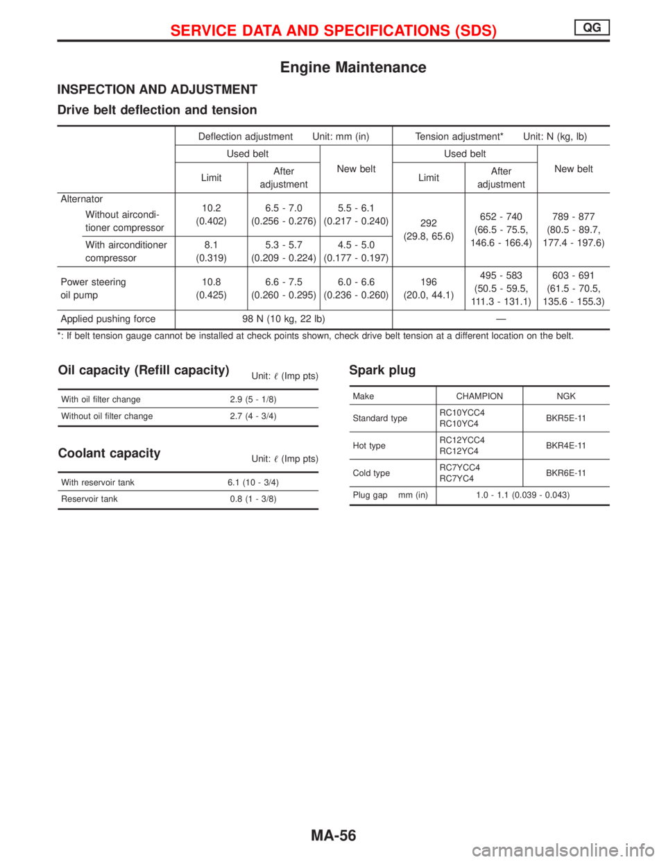
Drive belt deflection and tension
Deflection adjustment Unit: mm (in) Tension adjustment* Unit: N (kg, lb)
Used belt
New beltUsed belt
New belt
LimitAfter
adjustmentLimitAfter
adjustment
Alternator
Without aircondi-
tioner compressor10.2
(0.402)6.5 - 7.0
(0.256 - 0.276)5.5 - 6.1
(0.217 - 0.240)
292
(29.8, 65.6)652 - 740
(66.5 - 75.5,
146.6 - 166.4)789 - 877
(80.5 - 89.7,
177.4 - 197.6)
With airconditioner
compressor8.1
(0.319)5.3 - 5.7
(0.209 - 0.224)4.5 - 5.0
(0.177 - 0.197)
Power steering
oil pump10.8
(0.425)6.6 - 7.5
(0.260 - 0.295)6.0 - 6.6
(0.236 - 0.260)196
(20.0, 44.1)495 - 583
(50.5 - 59.5,
111.3 - 131.1)603 - 691
(61.5 - 70.5,
135.6 - 155.3)
Applied pushing force 98 N (10 kg, 22 lb)—
*: If belt tension gauge cannot be installed at check points shown, check drive belt tension at a different location on the belt.
Oil capacity (Refill capacity)Unit:�(Imp pts)
With oil filter change 2.9 (5 - 1/8)
Without oil filter change 2.7 (4 - 3/4)
Coolant capacityUnit:�(Imp pts)
With reservoir tank 6.1 (10 - 3/4)
Reservoir tank 0.8 (1 - 3/8)
Spark plug
Make CHAMPION NGK
Standard typeRC10YCC4
RC10YC4BKR5E-11
Hot typeRC12YCC4
RC12YC4BKR4E-11
Cold typeRC7YCC4
RC7YC4BKR6E-11
Plug gap mm (in) 1.0 - 1.1 (0.039 - 0.043)
SERVICE DATA AND SPECIFICATIONS (SDS)QG
MA-56
Page 2074 of 2267
Engine Maintenance
INSPECTION AND ADJUSTMENT
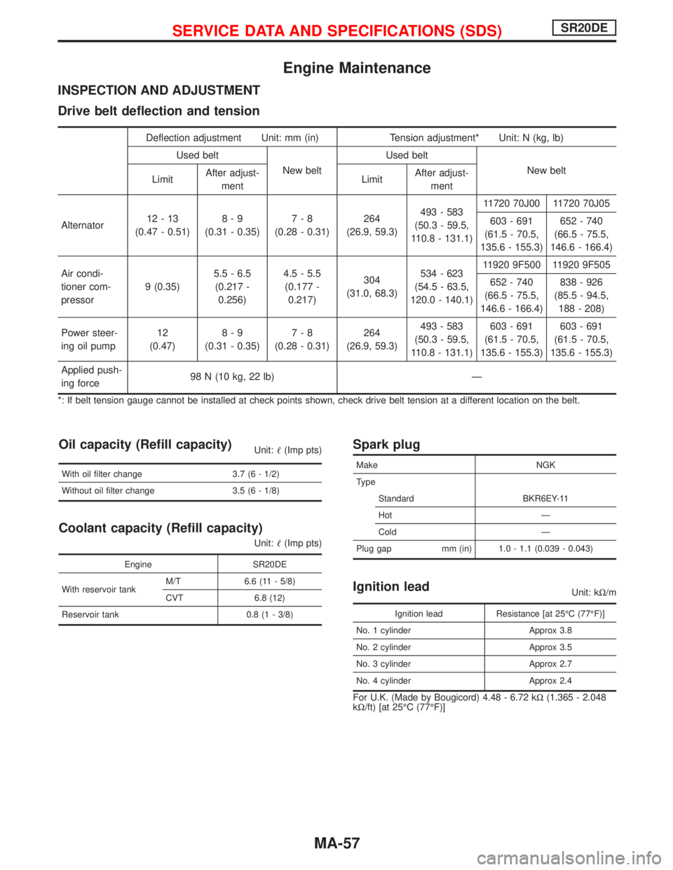
Drive belt deflection and tension
Deflection adjustment Unit: mm (in) Tension adjustment* Unit: N (kg, lb)
Used belt
New beltUsed belt
New belt
LimitAfter adjust-
mentLimitAfter adjust-
ment
Alternator12-13
(0.47 - 0.51)8-9
(0.31 - 0.35)7-8
(0.28 - 0.31)264
(26.9, 59.3)493 - 583
(50.3 - 59.5,
110.8 - 131.1)11720 70J00 11720 70J05
603 - 691
(61.5 - 70.5,
135.6 - 155.3)652 - 740
(66.5 - 75.5,
146.6 - 166.4)
Air condi-
tioner com-
pressor9 (0.35)5.5 - 6.5
(0.217 -
0.256)4.5 - 5.5
(0.177 -
0.217)304
(31.0, 68.3)534 - 623
(54.5 - 63.5,
120.0 - 140.1)11920 9F500 11920 9F505
652 - 740
(66.5 - 75.5,
146.6 - 166.4)838 - 926
(85.5 - 94.5,
188 - 208)
Power steer-
ing oil pump12
(0.47)8-9
(0.31 - 0.35)7-8
(0.28 - 0.31)264
(26.9, 59.3)493 - 583
(50.3 - 59.5,
110.8 - 131.1)603 - 691
(61.5 - 70.5,
135.6 - 155.3)603 - 691
(61.5 - 70.5,
135.6 - 155.3)
Applied push-
ing force98 N (10 kg, 22 lb)—
*: If belt tension gauge cannot be installed at check points shown, check drive belt tension at a different location on the belt.
Oil capacity (Refill capacity)Unit:�(Imp pts)
With oil filter change 3.7 (6 - 1/2)
Without oil filter change 3.5 (6 - 1/8)
Coolant capacity (Refill capacity)
Unit:�(Imp pts)
Engine SR20DE
With reservoir tankM/T 6.6 (11 - 5/8)
CVT 6.8 (12)
Reservoir tank 0.8 (1 - 3/8)
Spark plug
Make NGK
Ty p e
Standard BKR6EY-11
Hot—
Cold—
Plug gap mm (in) 1.0 - 1.1 (0.039 - 0.043)
Ignition leadUnit: kΩ/m
Ignition lead Resistance [at 25°C(77°F)]
No. 1 cylinder Approx 3.8
No. 2 cylinder Approx 3.5
No. 3 cylinder Approx 2.7
No. 4 cylinder Approx 2.4
For U.K. (Made by Bougicord) 4.48 - 6.72 kΩ(1.365 - 2.048
kΩ/ft) [at 25°C (77°F)]
SERVICE DATA AND SPECIFICATIONS (SDS)SR20DE
MA-57
Page 2075 of 2267
Engine Maintenance
INSPECTION AND ADJUSTMENT
Drive belt deflection
Deflection adjustment Unit: mm (in)
Used belt
New belt
Limit After adjustment
Alternator 17 (0.67)10.5 - 12.5
(0.413 - 0.492)8.5 - 10.5
(0.335 - 0.413)
Air conditioner compressor 17 (0.67)11.5 - 13.5
(0.453 - 0.531)9.5 - 11.5
(0.374 - 0.453)
Power steering oil pump 8 (0.31)5-7
(0.20 - 0.28)4-6
(0.16 - 0.24)
Applied pushing force 98 N (10 kg, 22 lb)
Coolant capacity (Refill capacity)
Unit:�(Imp pts)
With reservoir tank 6.4 (11 - 1/4)
Reservoir tank 0.8 (1 - 3/8)
Engine oil capacity (Refill capacity)
Unit:�(Imp pts)
With oil filter 5.0 (8 - 3/4)
Without oil filter 4.5 (7 - 7/8)
Injection nozzle
Unit: kPa (bar, kg/cm2, psi)
Injection pressure 12,749 (127.5, 130, 1,849)
SERVICE DATA AND SPECIFICATIONS (SDS)CD20T
MA-58
Page 2171 of 2267
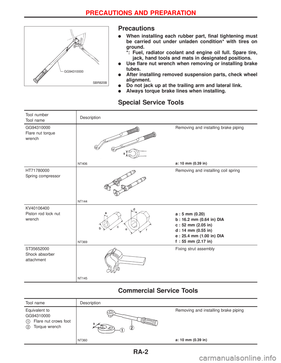
Precautions
lWhen installing each rubber part, final tightening must
be carried out under unladen condition* with tires on
ground.
*: Fuel, radiator coolant and engine oil full. Spare tire,
jack, hand tools and mats in designated positions.
lUse flare nut wrench when removing or installing brake
tubes.
lAfter installing removed suspension parts, check wheel
alignment.
lDo not jack up at the trailing arm and lateral link.
lAlways torque brake lines when installing.
Special Service Tools
Tool number
Tool nameDescription
GG94310000
Flare nut torque
wrench
NT406
Removing and installing brake piping
a: 10 mm (0.39 in)
HT71780000
Spring compressor
NT144
Removing and installing coil spring
KV40106400
Piston rod lock nut
wrench
NT369
a : 5 mm (0.20)
b : 16.2 mm (0.64 in) DIA
c : 52 mm (2.05 in)
d : 14 mm (0.55 in)
e : 25.4 mm (1.00 in) DIA
f : 55 mm (2.17 in)
ST35652000
Shock absorber
attachment
NT145
Fixing strut assembly
Commercial Service Tools
Tool name Description
Equivalent to
GG94310000
p1Flare nut crows foot
p2Torque wrench
NT360
Removing and installing brake piping
a: 10 mm (0.39 in)
SBR820B GG94310000
PRECAUTIONS AND PREPARATION
RA-2
Page 2173 of 2267
p1Coil spring
p2Shock absorberp3Torsion beam
p4Lateral linkp5Control rod
NRA004
98 - 118 (10 - 12, 73 - 87)
42-57
(4.3 - 5.8, 31 - 42)
p1
p2
p3
p4
p5
98 - 118 (10 - 12, 73 - 87) Front
: Do not re-use
: N´m (kg-m, ft-lb)
SEC. 431
When installing each rubber part, final tightening
must be carried out under unladen condition*
with tires on ground.
* Fuel, radiator coolant and engine oil full.
Spare tire, jack, hand tools and mats in
designated positions.
REAR SUSPENSION SYSTEM
RA-4
Page 2178 of 2267
p1Washer
p2Bushing
p3Shock absorber mounting
bracket
p4Bound bumper cover
p5Bound bumper
p6Coil spring
p7Shock absorber
p8Torsion beam
p9Lateral link
p10Control rod
p11ABS sensor
NRA018
SEC. 431
When installing each rubber part, final tightening
must be carried out under unladen condition*
with tires on ground.
* Fuel, radiator coolant and engine oil full.
Spare tire, jack, hand tools and mats in
designated positions.
36 - 47 (3.7 - 4.7, 27 - 34)
p1
p2
p3
42-57
(4.3 - 5.8,
31 - 42)
p4
p5
p6
p7
25-33
(2.6 - 3.3,
19 - 24)
p8
98-118
(10 - 12, 73 - 87)p9
p10
98-118
(10 - 12,
73 - 87)
59-78
(6.1 - 7.9,
44 - 57)
Front
98 - 118 (10 - 12, 73 - 87)
p11
98-118
(10 - 12, 73 - 87)
: N´m (kg-m, ft-lb)
: Do not re-use
98 - 118 (10 - 12, 73 - 87)
REAR SUSPENSION
RA-9