1999 NISSAN PRIMERA turn signal
[x] Cancel search: turn signalPage 109 of 2267
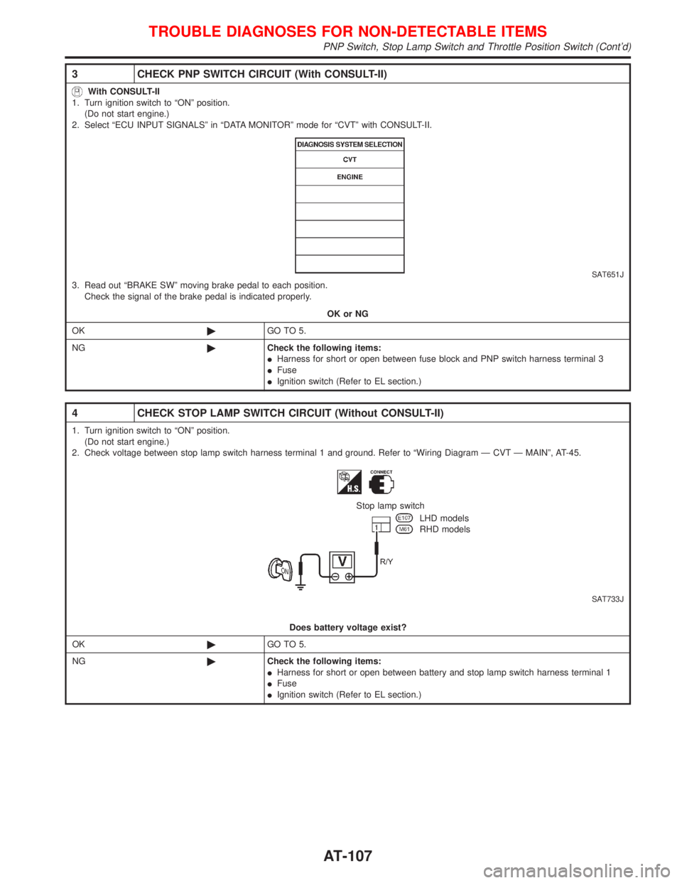
3 CHECK PNP SWITCH CIRCUIT (With CONSULT-II)
With CONSULT-II
1. Turn ignition switch to ªONº position.
(Do not start engine.)
2. Select ªECU INPUT SIGNALSº in ªDATA MONITORº mode for ªCVTº with CONSULT-II.
SAT651J3. Read out ªBRAKE SWº moving brake pedal to each position.
Check the signal of the brake pedal is indicated properly.
OK or NG
OK©GO TO 5.
NG©Check the following items:
IHarness for short or open between fuse block and PNP switch harness terminal 3
IFuse
IIgnition switch (Refer to EL section.)
4 CHECK STOP LAMP SWITCH CIRCUIT (Without CONSULT-II)
1. Turn ignition switch to ªONº position.
(Do not start engine.)
2. Check voltage between stop lamp switch harness terminal 1 and ground. Refer to ªWiring Diagram Ð CVT Ð MAINº, AT-45.
SAT733J
Stop lamp switch
LHD models
RHD models
Does battery voltage exist?
OK©GO TO 5.
NG©Check the following items:
IHarness for short or open between battery and stop lamp switch harness terminal 1
IFuse
IIgnition switch (Refer to EL section.)
TROUBLE DIAGNOSES FOR NON-DETECTABLE ITEMS
PNP Switch, Stop Lamp Switch and Throttle Position Switch (Cont'd)
AT-107
Page 110 of 2267
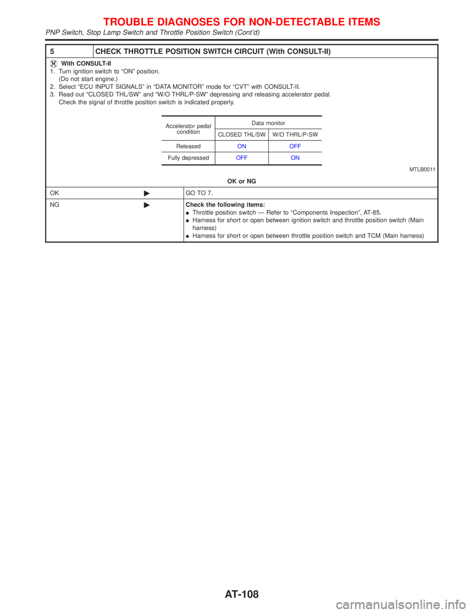
5 CHECK THROTTLE POSITION SWITCH CIRCUIT (With CONSULT-II)
With CONSULT-II
1. Turn ignition switch to ªONº position.
(Do not start engine.)
2. Select ªECU INPUT SIGNALSº in ªDATA MONITORº mode for ªCVTº with CONSULT-II.
3. Read out ªCLOSED THL/SWº and ªW/O THRL/P-SWº depressing and releasing accelerator pedal.
Check the signal of throttle position switch is indicated properly.
OK or NG
OK©GO TO 7.
NG©Check the following items:
IThrottle position switch Ð Refer to ªComponents Inspectionº, AT-85.
IHarness for short or open between ignition switch and throttle position switch (Main
harness)
IHarness for short or open between throttle position switch and TCM (Main harness)
Accelerator pedal
conditionData monitor
CLOSED THL/SW W/O THRL/P-SW
ReleasedON OFF
Fully depressedOFF ON
MTLB0011
TROUBLE DIAGNOSES FOR NON-DETECTABLE ITEMS
PNP Switch, Stop Lamp Switch and Throttle Position Switch (Cont'd)
AT-108
Page 111 of 2267
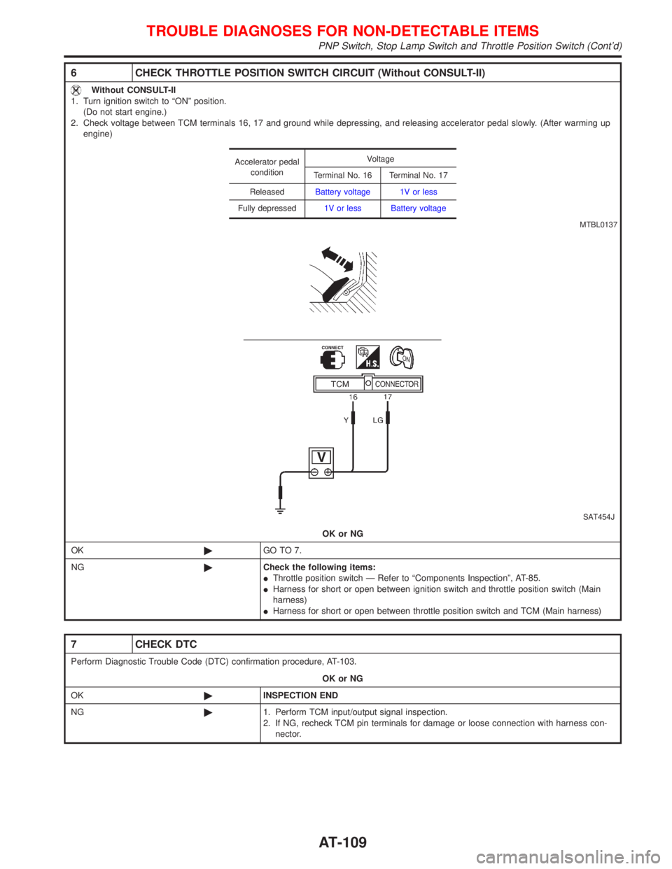
6 CHECK THROTTLE POSITION SWITCH CIRCUIT (Without CONSULT-II)
Without CONSULT-II
1. Turn ignition switch to ªONº position.
(Do not start engine.)
2. Check voltage between TCM terminals 16, 17 and ground while depressing, and releasing accelerator pedal slowly. (After warming up
engine)
SAT454J
OK or NG
OK©GO TO 7.
NG©Check the following items:
IThrottle position switch Ð Refer to ªComponents Inspectionº, AT-85.
IHarness for short or open between ignition switch and throttle position switch (Main
harness)
IHarness for short or open between throttle position switch and TCM (Main harness)
Accelerator pedal
conditionVoltage
Terminal No. 16 Terminal No. 17
ReleasedBattery voltage 1V or less
Fully depressed1V or less Battery voltage
MTBL0137
7 CHECK DTC
Perform Diagnostic Trouble Code (DTC) confirmation procedure, AT-103.
OK or NG
OK©INSPECTION END
NG©1. Perform TCM input/output signal inspection.
2. If NG, recheck TCM pin terminals for damage or loose connection with harness con-
nector.
TROUBLE DIAGNOSES FOR NON-DETECTABLE ITEMS
PNP Switch, Stop Lamp Switch and Throttle Position Switch (Cont'd)
AT-109
Page 193 of 2267
![NISSAN PRIMERA 1999 Electronic Repair Manual SELF-DIAGNOSTIC RESULTS MODE
Diagnostic item Diagnostic item is detected when...Diagnostic
procedure
FR RH SENSORH
[OPEN]
lCircuit for front right wheel sensor is open.
(An abnormally high input volta NISSAN PRIMERA 1999 Electronic Repair Manual SELF-DIAGNOSTIC RESULTS MODE
Diagnostic item Diagnostic item is detected when...Diagnostic
procedure
FR RH SENSORH
[OPEN]
lCircuit for front right wheel sensor is open.
(An abnormally high input volta](/manual-img/5/57377/w960_57377-192.png)
SELF-DIAGNOSTIC RESULTS MODE
Diagnostic item Diagnostic item is detected when...Diagnostic
procedure
FR RH SENSORH
[OPEN]
lCircuit for front right wheel sensor is open.
(An abnormally high input voltage is entered.)1
FR LH SENSORH
[OPEN]
lCircuit for front left wheel sensor is open.
(An abnormally high input voltage is entered.)1
RR RH SENSORH
[OPEN]
lCircuit for rear right sensor is open.
(An abnormally high input voltage is entered.)1
RR LH SENSORH
[OPEN]
lCircuit for rear left sensor is open.
(An abnormally high input voltage is entered.)1
FR RH SENSORH
[SHORT]
lCircuit for front right wheel sensor is shorted.
(An abnormally low input voltage is entered.)1
FR LH SENSORH
[SHORT]
lCircuit for front left wheel sensor is shorted.
(An abnormally low input voltage is entered.)1
RR RH SENSORH
[SHORT]
lCircuit for rear right sensor is shorted.
(An abnormally low input voltage is entered.)1
RR LH SENSOR
[SHORT]
lCircuit for rear left sensor is shorted.
(An abnormally low input voltage is entered.)1
ABS SENSORH
[ABNORMAL SIGNAL]
lTeeth damage on sensor rotor or improper installation of wheel sensor.
(Abnormal wheel sensor signal is entered.)1
FR RH IN ABS SOL
[OPEN]
lCircuit for front right inlet solenoid valve is open.
(An abnormally low output voltage is entered.)2
FR LH IN ABS SOL
[OPEN]
lCircuit for front left inlet solenoid valve is open.
(An abnormally low output voltage is entered.)2
RR RH IN ABS SOL
[OPEN]
lCircuit for rear right inlet solenoid valve is open.
(An abnormally low output voltage is entered.)2
RR LH IN ABS SOL
[OPEN]
lCircuit for rear left inlet solenoid valve is open.
(An abnormally low output voltage is entered.)2
FR RH IN ABS SOL
[SHORT]
lCircuit for front right inlet solenoid valve is shorted.
(An abnormally high output voltage is entered.)2
FR LH IN ABS SOL
[SHORT]
lCircuit for front left inlet solenoid valve is shorted.
(An abnormally high output voltage is entered.)2
RR RH IN ABS SOL
[SHORT]
lCircuit for rear right inlet solenoid valve is shorted.
(An abnormally high output voltage is entered.)2
RR LH IN ABS SOL
[SHORT]
lCircuit for rear left inlet solenoid valve is shorted.
(An abnormally high output voltage is entered.)2
FR RH OUT ABS SOL
[OPEN]
lCircuit for front right outlet solenoid valve is open.
(An abnormally low output voltage is entered.)2
FR LH OUT ABS SOL
[OPEN]
lCircuit for front left outlet solenoid valve is open.
(An abnormally low output voltage is entered.)2
RR RH OUT ABS SOL
[OPEN]
lCircuit for rear right outlet solenoid valve is open.
(An abnormally low output voltage is entered.)2
RR LH OUT ABS SOL
[OPEN]
lCircuit for rear left outlet solenoid valve is open.
(An abnormally low output voltage is entered.)2
FR RH OUT ABS SOL
[SHORT]
lCircuit for front right outlet solenoid valve is shorted.
(An abnormally high output voltage is entered.)2
FR LH OUT ABS SOL
[SHORT]
lCircuit for front left outlet solenoid valve is shorted.
(An abnormally high output voltage is entered.)2
RR RH OUT ABS SOL
[SHORT]
lCircuit for rear right outlet solenoid valve is shorted.
(An abnormally high output voltage is entered.)2
RR LH OUT ABS SOL
[SHORT]
lCircuit for rear left outlet solenoid valve is shorted.
(An abnormally high output voltage is entered.)2
ABS ACTUATOR RELAY
[ABNORMAL]
lActuator solenoid valve relay is ON, even control unit sends off signal.lActuator solenoid valve relay is OFF, even control unit sends on signal.2
ABS MOTOR RELAY
[ABNORMAL]
lCircuit for actuator motor is open or shorted.lActuator motor relay is stuck.lCircuit for actuator is open or shorted.3
BATTERY VOLT
[VB-LOW]
lPower source voltage supplied to ABS control unit is abnormally low. 4
CONTROL UNIT
lFunction of calculation in ABS control unit has failed. 5
H: If one or more wheels spin on a rough or slippery road for 40 seconds or more, the ABS warning lamp will illuminate. This does
not indicate a malfunction. Only in the case of the short-circuit after repair the ABS warning lamp also illuminates when the igni-
tion switch is turned ªONº. In this case, drive the vehicle at speeds greater than 30 km/h (19 MPH) for approximately 1 minute
as specified in ªSELF-DIAGNOSIS PROCEDUREº, BR-70. Check to ensure that the ABS warning lamp goes out while the
vehicle is being driven.
Trouble Diagnosis Ð General Description
CONSULT-II Inspection Procedure (Cont'd)
BR-71
Page 195 of 2267
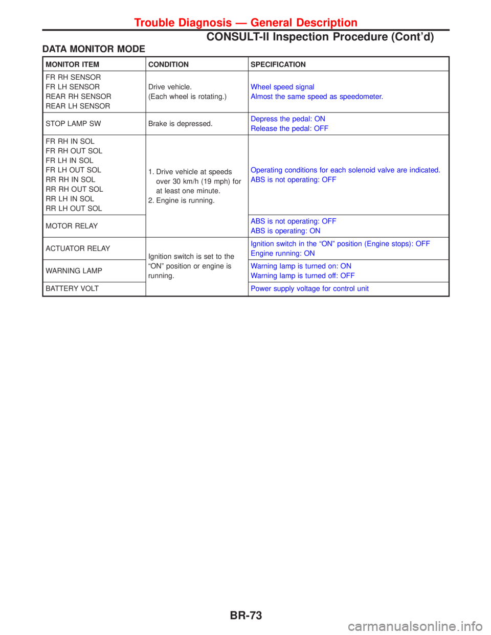
DATA MONITOR MODE
MONITOR ITEM CONDITION SPECIFICATION
FR RH SENSOR
FR LH SENSOR
REAR RH SENSOR
REAR LH SENSORDrive vehicle.
(Each wheel is rotating.)Wheel speed signal
Almost the same speed as speedometer.
STOP LAMP SW Brake is depressed.Depress the pedal: ON
Release the pedal: OFF
FR RH IN SOL
FR RH OUT SOL
FR LH IN SOL
FR LH OUT SOL
RR RH IN SOL
RR RH OUT SOL
RR LH IN SOL
RR LH OUT SOL1. Drive vehicle at speeds
over 30 km/h (19 mph) for
at least one minute.
2. Engine is running.Operating conditions for each solenoid valve are indicated.
ABS is not operating: OFF
MOTOR RELAYABS is not operating: OFF
ABS is operating: ON
ACTUATOR RELAY
Ignition switch is set to the
ªONº position or engine is
running.Ignition switch in the ªONº position (Engine stops): OFF
Engine running: ON
WARNING LAMPWarning lamp is turned on: ON
Warning lamp is turned off: OFF
BATTERY VOLTPower supply voltage for control unit
Trouble Diagnosis Ð General Description
CONSULT-II Inspection Procedure (Cont'd)
BR-73
Page 309 of 2267
Glow Control System
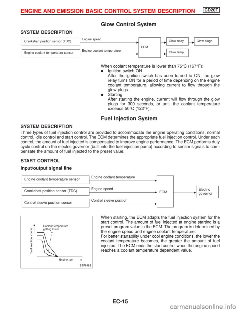
SYSTEM DESCRIPTION
Crankshaft position sensor (TDC)EEngine speed
ECMEGlow relayEGlow plugs
Engine coolant temperature sensorEEngine coolant temperatureEGlow lamp
When coolant temperature is lower than 75ÉC (167ÉF):
lIgnition switch ON
After the ignition switch has been turned to ON, the glow
relay turns ON for a period of time depending on the engine
coolant temperature, allowing current to flow through the
glow plugs.
lStarting
After starting the engine, current will flow through the glow
plugs for 300 seconds, or until the coolant temperature
exceeds 50ÉC (122ÉF).
Fuel Injection System
SYSTEM DESCRIPTION
Three types of fuel injection control are provided to accommodate the engine operating conditions; normal
control, idle control and start control. The ECM determines the appropriate fuel injection control. Under each
control, the amount of fuel injected is compensated to improve engine performance. The ECM performs duty
cycle control on the electric governor (built into the fuel injection pump) according to sensor signals to com-
pensate the amount of fuel injected to the preset value.
START CONTROL
Input/output signal line
Engine coolant temperature sensorEEngine coolant temperature
ECM
EElectric
governorCrankshaft position sensor (TDC)EEngine speed
Control sleeve position sensor
EControl sleeve position
When starting, the ECM adapts the fuel injection system for the
start control. The amount of fuel injected at engine starting is a
preset program value in the ECM. The program is determined by
the engine speed and engine coolant temperature.
For better startability under cool engine conditions, the lower the
coolant temperature becomes, the greater the amount of fuel
injected. The ECM ends the start control when the engine speed
reaches a coolant temperature dependent value.
SEF648S Coolant temperature
getting lower
Engine rpm
Fuel injection volume
ENGINE AND EMISSION BASIC CONTROL SYSTEM DESCRIPTIONCD20T
EC-15
Page 314 of 2267
Air Conditioning Cut Control
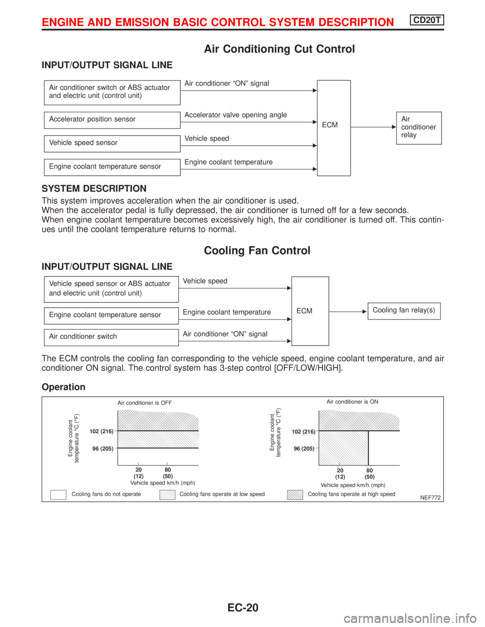
INPUT/OUTPUT SIGNAL LINE
Air conditioner switch or ABS actuator
and electric unit (control unit)EAir conditioner ªONº signal
ECM
EAir
conditioner
relayAccelerator position sensorEAccelerator valve opening angle
Vehicle speed sensor
EVehicle speed
Engine coolant temperature sensor
EEngine coolant temperature
SYSTEM DESCRIPTION
This system improves acceleration when the air conditioner is used.
When the accelerator pedal is fully depressed, the air conditioner is turned off for a few seconds.
When engine coolant temperature becomes excessively high, the air conditioner is turned off. This contin-
ues until the coolant temperature returns to normal.
Cooling Fan Control
INPUT/OUTPUT SIGNAL LINE
Vehicle speed sensor or ABS actuator
and electric unit (control unit)EVehicle speed
ECM
ECooling fan relay(s)Engine coolant temperature sensorEEngine coolant temperature
Air conditioner switch
EAir conditioner ªONº signal
The ECM controls the cooling fan corresponding to the vehicle speed, engine coolant temperature, and air
conditioner ON signal. The control system has 3-step control [OFF/LOW/HIGH].
Operation
NEF772
Engine coolant
temperature ÉC (ÉF)
Air conditioner is OFF
.102 (216)
.96 (205)
.20
(12).80
(50)
Vehicle speed km/h (mph)
Cooling fans do not operateCooling fans operate at high speed
Engine coolant
temperature ÉC (ÉF)
Vehicle speed km/h (mph)
.20
(12).80
(50)
.102 (216)
.96 (205)Air conditioner is ON
Cooling fans operate at low speed
ENGINE AND EMISSION BASIC CONTROL SYSTEM DESCRIPTIONCD20T
EC-20
Page 333 of 2267
Diagnostic Trouble Chart
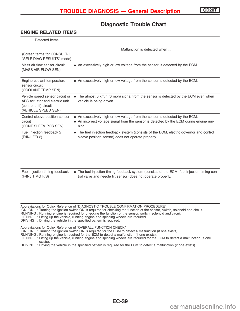
ENGINE RELATED ITEMS
Detected items
(Screen terms for CONSULT-II,
ªSELF-DIAG RESULTSº mode)Malfunction is detected when ...
Mass air flow sensor circuit
(MASS AIR FLOW SEN)
lAn excessively high or low voltage from the sensor is detected by the ECM.
Engine coolant temperature
sensor circuit
(COOLANT TEMP SEN)
lAn excessively high or low voltage from the sensor is detected by the ECM.
Vehicle speed sensor circuit or
ABS actuator and electric unit
(control unit) circuit
(VEHICLE SPEED SEN)
lThe almost 0 km/h (0 mph) signal from the sensor is detected by the ECM even when
vehicle is being driven.
Control sleeve position sensor
circuit
(CONT SLEEV POS SEN)
lAn excessively high or low voltage from the sensor is detected by the ECM.
lAn incorrect voltage signal from the sensor is detected by the ECM during engine run-
ning.
Fuel injection feedback 2
(F/INJ F/B 2)
lThe fuel injection feedback system (consists of the ECM, electric governor and control
sleeve position sensor) does not operate properly.
Fuel injection timing feedback
(F/INJ TIMG F/B)
lThe fuel injection timing feedback system (consists of the ECM, fuel injection timing con-
trol valve and needle lift sensor) does not operate properly.
Abbreviations for Quick Reference of ªDIAGNOSTIC TROUBLE CONFIRMATION PROCEDUREº
IGN: ON : Turning the ignition switch ON is required for checking the function of the sensor, switch, solenoid and circuit.
RUNNING : Running engine is required for checking the function of the sensor, switch, solenoid and circuit.
LIFTING : Lifting up the vehicle, running engine and spinning wheels are required.
DRIVING : Driving the vehicle in the specified pattern is required.
Abbreviations for Quick Reference of ªOVERALL FUNCTION CHECKº
IGN: ON : Turning the ignition switch ON is required for the ECM to detect a malfunction (if one exists).
RUNNING : Running engine is required for the ECM to detect a malfunction (if one exists).
LIFTING : Lifting up the vehicle, running engine and spinning wheels are required for the ECM to detect a malfunction (if one
exists).
DRIVING : Driving the vehicle in the specified pattern is required for the ECM to detect a malfunction (if one exists).
TROUBLE DIAGNOSIS Ð General DescriptionCD20T
EC-39